EP0593336A1 - Lösbare Befestigung zum Verbinden einer Trägerplatte mit einem Bauelement und Verbinder mit einer solchen Befestigung - Google Patents
Lösbare Befestigung zum Verbinden einer Trägerplatte mit einem Bauelement und Verbinder mit einer solchen Befestigung Download PDFInfo
- Publication number
- EP0593336A1 EP0593336A1 EP93402452A EP93402452A EP0593336A1 EP 0593336 A1 EP0593336 A1 EP 0593336A1 EP 93402452 A EP93402452 A EP 93402452A EP 93402452 A EP93402452 A EP 93402452A EP 0593336 A1 EP0593336 A1 EP 0593336A1
- Authority
- EP
- European Patent Office
- Prior art keywords
- removable fastener
- retention
- fastener according
- pin
- fastener
- Prior art date
- Legal status (The legal status is an assumption and is not a legal conclusion. Google has not performed a legal analysis and makes no representation as to the accuracy of the status listed.)
- Granted
Links
- 230000014759 maintenance of location Effects 0.000 claims abstract description 25
- 230000001747 exhibiting effect Effects 0.000 abstract 1
- 239000002184 metal Substances 0.000 description 4
- 238000000605 extraction Methods 0.000 description 3
- 238000003780 insertion Methods 0.000 description 2
- 230000037431 insertion Effects 0.000 description 2
- 238000000034 method Methods 0.000 description 2
- 239000004020 conductor Substances 0.000 description 1
- 238000002788 crimping Methods 0.000 description 1
- 230000006866 deterioration Effects 0.000 description 1
- 230000000694 effects Effects 0.000 description 1
- 239000012811 non-conductive material Substances 0.000 description 1
Images
Classifications
-
- F—MECHANICAL ENGINEERING; LIGHTING; HEATING; WEAPONS; BLASTING
- F16—ENGINEERING ELEMENTS AND UNITS; GENERAL MEASURES FOR PRODUCING AND MAINTAINING EFFECTIVE FUNCTIONING OF MACHINES OR INSTALLATIONS; THERMAL INSULATION IN GENERAL
- F16B—DEVICES FOR FASTENING OR SECURING CONSTRUCTIONAL ELEMENTS OR MACHINE PARTS TOGETHER, e.g. NAILS, BOLTS, CIRCLIPS, CLAMPS, CLIPS OR WEDGES; JOINTS OR JOINTING
- F16B21/00—Means for preventing relative axial movement of a pin, spigot, shaft or the like and a member surrounding it; Stud-and-socket releasable fastenings
- F16B21/06—Releasable fastening devices with snap-action
- F16B21/08—Releasable fastening devices with snap-action in which the stud, pin, or spigot has a resilient part
- F16B21/088—Releasable fastening devices with snap-action in which the stud, pin, or spigot has a resilient part the stud, pin or spigot being integrally formed with the component to be fastened, e.g. forming part of the sheet, plate or strip
-
- H—ELECTRICITY
- H01—ELECTRIC ELEMENTS
- H01R—ELECTRICALLY-CONDUCTIVE CONNECTIONS; STRUCTURAL ASSOCIATIONS OF A PLURALITY OF MUTUALLY-INSULATED ELECTRICAL CONNECTING ELEMENTS; COUPLING DEVICES; CURRENT COLLECTORS
- H01R12/00—Structural associations of a plurality of mutually-insulated electrical connecting elements, specially adapted for printed circuits, e.g. printed circuit boards [PCB], flat or ribbon cables, or like generally planar structures, e.g. terminal strips, terminal blocks; Coupling devices specially adapted for printed circuits, flat or ribbon cables, or like generally planar structures; Terminals specially adapted for contact with, or insertion into, printed circuits, flat or ribbon cables, or like generally planar structures
- H01R12/50—Fixed connections
- H01R12/51—Fixed connections for rigid printed circuits or like structures
- H01R12/55—Fixed connections for rigid printed circuits or like structures characterised by the terminals
- H01R12/58—Fixed connections for rigid printed circuits or like structures characterised by the terminals terminals for insertion into holes
-
- H—ELECTRICITY
- H01—ELECTRIC ELEMENTS
- H01R—ELECTRICALLY-CONDUCTIVE CONNECTIONS; STRUCTURAL ASSOCIATIONS OF A PLURALITY OF MUTUALLY-INSULATED ELECTRICAL CONNECTING ELEMENTS; COUPLING DEVICES; CURRENT COLLECTORS
- H01R12/00—Structural associations of a plurality of mutually-insulated electrical connecting elements, specially adapted for printed circuits, e.g. printed circuit boards [PCB], flat or ribbon cables, or like generally planar structures, e.g. terminal strips, terminal blocks; Coupling devices specially adapted for printed circuits, flat or ribbon cables, or like generally planar structures; Terminals specially adapted for contact with, or insertion into, printed circuits, flat or ribbon cables, or like generally planar structures
- H01R12/70—Coupling devices
- H01R12/7005—Guiding, mounting, polarizing or locking means; Extractors
- H01R12/7011—Locking or fixing a connector to a PCB
- H01R12/7017—Snap means
-
- H—ELECTRICITY
- H01—ELECTRIC ELEMENTS
- H01R—ELECTRICALLY-CONDUCTIVE CONNECTIONS; STRUCTURAL ASSOCIATIONS OF A PLURALITY OF MUTUALLY-INSULATED ELECTRICAL CONNECTING ELEMENTS; COUPLING DEVICES; CURRENT COLLECTORS
- H01R12/00—Structural associations of a plurality of mutually-insulated electrical connecting elements, specially adapted for printed circuits, e.g. printed circuit boards [PCB], flat or ribbon cables, or like generally planar structures, e.g. terminal strips, terminal blocks; Coupling devices specially adapted for printed circuits, flat or ribbon cables, or like generally planar structures; Terminals specially adapted for contact with, or insertion into, printed circuits, flat or ribbon cables, or like generally planar structures
- H01R12/70—Coupling devices
- H01R12/7005—Guiding, mounting, polarizing or locking means; Extractors
- H01R12/7011—Locking or fixing a connector to a PCB
- H01R12/7064—Press fitting
Definitions
- the present invention relates to a removable fastener for securing at least one flat support to an element.
- the present invention aims to overcome the aforementioned drawback.
- a removable fastener for securing at least one flat support such as a circuit support to an element characterized in that it comprises an axial retention device having a first retention means ensuring its retention on a first pin carried by said element and at least one second retention means ensuring the retention of the flat support.
- the first and second retention means are coaxial.
- the first and second retention means are offset laterally with respect to each other, and preferably over at least part of the periphery of at least one second pin by said element.
- the axial retention device is advantageously electrically conductive and the flat support can then comprise at least one metallized hole making it possible to ensure electrical continuity between the removable fastener and the flat support.
- the second retention means can advantageously have at least one elastic element arranged in such a way that, when it is introduced into the flat support, it deforms so as to produce a force locking, in particular by coming into abutment against the second pin .
- the elastic element is a V-shaped arch whose proximal ends of the branches are integral with the fastener.
- the fastener can constitute a shielding plate.
- the first retention element can be forcibly locked on the first pin.
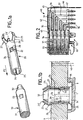
- a central body 1 has a cylindrical pin designated by the general reference 30 and having a cylindrical region 31, at least one housing 33 and one end 32 of frustoconical shape.
- Contact elements 40 are housed (for example by crimping) in the insulating body 1, and pass through a printed circuit 9.
- the cylindrical pin 30 is integral with the central body 1 and is made of analogous to a hot deformable pin of the prior art.
- a piece 20 of metal has a hollow cylindrical body 24 having a notch 26 and at least one elastic arm 22 intended to snap into the housing 33.
- the piece 20 has a base end 25 abutting below the base of the pin 30, and an upper end 29 which is extended by elastic arms 23, here three in number distributed at 120 °, but could for example be four in number distributed at 90 °.
- the elastic arm 23 has a proximal region 27 extending outward, and a distal region 23 'forming an elbow with the region 27, the distal region 23' being directed inward.
- the proximal region 27 acts as a snap stopper to hold in place the printed circuit 9 in abutment against an upper face 41 of the insulating central body 1.
- the cylindrical body 20 is first introduced in the direction of the arrow F2 until the tabs 22 snap into the housings 33. Then, the opening (or openings) 21 of the printed circuit 9 is presented to the distal end 23 'of the elastic arm 23.
- the inwardly folded shape of the distal ends 23' allows a chamfer effect when the opening is introduced 21.
- the elastic arms 23 are pushed inwards, which allows the introduction of the printed circuit 9 until it abuts against the face 41 of the central body 1 in a position in which a latching phenomenon occurs, on the face 42 of the printed circuit 9, of the 'proximal end 27 by elastic deployment of the arms 23 outwards.
- a frustoconical part 32 at the end of the cylindrical pin 30 makes it possible to define a stop for the folding of the distal ends 23 ′ of the elastic arms 23 so as to avoid accidental deterioration of these during the introduction of the printed circuit 9. It should in fact be recalled that these parts can be very small.
- the diameter of the pin 30 is of the order of 1 mm.
- the part 20 can be removed by rotating it around the axis of the hollow cylinder 24 so as to release the elastic arm (s) 22 from the housing (s) 33.
- the presence of the slot 26 makes it easier to introduce the hollow cylindrical body 24 of the part 20 into the cylindrical pin 30 by spacing the edges of the slot 26 so as to avoid mechanical stresses harmful to the cylindrical pin 30.
- the presence of the slot 26 also makes it easier to disassemble the hollow cylindrical body 24 of the cylindrical pin 30. It will be noted that, in the case where it is not considered necessary to protect the end of the elastic arms 23, the body 31 no longer needs to protrude from the printed circuit 9.
- the device in addition to the dismantling of the printed circuit 9 which already existed in the previous embodiments, has the further advantage of allowing either a removable fixing method with a hollow cylindrical body 24, or using the cylindrical pin 30 as a hot-deformable pin. It suffices to give it the appropriate profile.
- the connector according to the invention can also make it possible to secure to the central body, in addition to a printed circuit, at least one other support, for example a shielding plate.
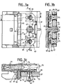
- FIG. 2 represents a connector 40 for connection between a male connector and a daughter card.
- a shielding element (general reference 40) has a rear region 46 ending in forced insertion contacts ("press fit") 47, and a front region 42 making an angle of 90 ° (fold 45) with the rear region 46.
- the front region 42 ends in a contact region 43.
- a fixing device designated by the general reference 50 In the vicinity of the male contacts 38 and in the front direction of the connector 40, is arranged a fixing device designated by the general reference 50 and making it possible to secure a flat support such as a printed circuit (daughter card 70) to the connector 40.
- This fixing device comprises a removable fastener designated by the general reference 60.
- the removable fastener 60 is constituted by a metal plate 61 having, in a median region, an opening 63 from which two curved fingers 63 point outwards.
- the plate 61 is translated parallel to the axis of a pin 81 secured to the front insulating body 31, the fingers 63 being housed in grooves 82 of the pin 81 arranged at 180 °.
- the fingers 63 provide a force locking of the plate since their end 63 'exerts a given pressure on the bottom of the respective grooves 82.
- An extraction force applied to the plate 61 forces the fingers 63 to arch. butt at the bottom of the grooves 82 to oppose an extraction. This extraction remains however possible without damaging the parts, but it will be understood that this device is not intended for many disassembly.
- the metal plate 60 (here performing a shielding plate function) also has two elastic devices having two arms 85 extending in the plane of the plate 60 and separated by a space 85 ', and extending by a folded arch 86 90 ° outwards, this arch 86 gradually tapering to its rounded top 87, which gives it a general shape of V.
- the space 85 ′ between the arms 85 is partially occupied by an extension 83 of a pin 82 of semi-circular section.
- the plate 60 once in place as indicated above, the daughter card 70 is presented and positioned so that the pin 81 passes through its opening 71 and that the pins (82, 83) and the arch 86 pass through its holes 75.
- the width of the arch 86 at its birth (rectilinear part 89) is substantially greater than the diameter of the metallized holes 75, which allows a force locking function by elastic folding of the hoop 86 in the direction of the extension 83 until possibly coming into abutment against it.
- a locking operation was also carried out here, allowing one or more disassembly.
- the disassembly force can be chosen, so that the daughter card 30 can be disassembled with a given force, then, that the fastener 60 can then be disassembled with a force greater than said given force.
- the plate 60 can be made of non-conductive material.
- the arch 86 can be replaced by two rectilinear or curved arms separated from each other (that is to say without the apex 87).
- the elastic arms 22 (FIGS. 1a, 1b) can be produced like the fingers 63 to obtain a force locking rather than a positive locking.
Landscapes
- Engineering & Computer Science (AREA)
- General Engineering & Computer Science (AREA)
- Mechanical Engineering (AREA)
- Multi-Conductor Connections (AREA)
- Coupling Device And Connection With Printed Circuit (AREA)
Applications Claiming Priority (2)
| Application Number | Priority Date | Filing Date | Title |
|---|---|---|---|
| FR9212208 | 1992-10-13 | ||
| FR9212208A FR2696878B1 (fr) | 1992-10-13 | 1992-10-13 | Attache amovible pour solidariser un support plat à un élément et connecteur la comportant. |
Publications (2)
| Publication Number | Publication Date |
|---|---|
| EP0593336A1 true EP0593336A1 (de) | 1994-04-20 |
| EP0593336B1 EP0593336B1 (de) | 2000-08-02 |
Family
ID=9434472
Family Applications (1)
| Application Number | Title | Priority Date | Filing Date |
|---|---|---|---|
| EP93402452A Expired - Lifetime EP0593336B1 (de) | 1992-10-13 | 1993-10-06 | Lösbare Befestigung zum Verbinden einer Trägerplatte mit einem Bauelement und Verbinder mit einer solchen Befestigung |
Country Status (4)
| Country | Link |
|---|---|
| US (1) | US5441423A (de) |
| EP (1) | EP0593336B1 (de) |
| DE (1) | DE69329137T2 (de) |
| FR (1) | FR2696878B1 (de) |
Cited By (2)
| Publication number | Priority date | Publication date | Assignee | Title |
|---|---|---|---|---|
| US6112911A (en) * | 1998-02-10 | 2000-09-05 | Molex Incorporated | Support assembly for board-mounted electrical appliance |
| EP1593291A4 (de) * | 2003-02-12 | 2007-11-14 | Amphenol Corp | Leiterplatte und buchsenbaugruppe |
Families Citing this family (5)
| Publication number | Priority date | Publication date | Assignee | Title |
|---|---|---|---|---|
| EP0985428A1 (de) | 1998-08-12 | 2000-03-15 | Pacesetter, Inc. | Herzschrittmacher mit sicherer R-Wellensynchronisierung während der Reizungskorrektur einer Vorhofsfibrillierung |
| US6328599B1 (en) * | 1998-12-18 | 2001-12-11 | Fci Americas Technology, Inc. | Electrical connector having mounting posts adapted to be received by a printed wiring board |
| DE10140910C2 (de) * | 2001-08-21 | 2003-07-17 | Lumberg Automation Components | Elektrischer Steckverbinder |
| US6485328B1 (en) * | 2001-12-19 | 2002-11-26 | Hon Hai Precision Ind. Co., Ltd. | Header connector with shell |
| DE102017219554A1 (de) * | 2017-11-03 | 2019-05-09 | Te Connectivity Germany Gmbh | Verfahren zur Montage einer Vielzahl von Einpresskontaktstiften in ein Gehäuse, Gehäusekomponente mit einer Vielzahl von Einpresskontaktstiften und elektrische Baugruppe mit einer solchen Gehäusekomponente |
Citations (10)
| Publication number | Priority date | Publication date | Assignee | Title |
|---|---|---|---|---|
| GB1017929A (en) * | 1963-04-30 | 1966-01-26 | Ind Electronic Hardware Corp | Improvements in or relating to multilayer circuitry with interrupted lines |
| US3774142A (en) * | 1972-05-10 | 1973-11-20 | Elco Corp | Sleeve for grounding bushing-mounted contact to plate |
| US4765036A (en) * | 1986-02-12 | 1988-08-23 | Nifco, Inc. | Clip for protecting coated surface |
| US4889502A (en) * | 1987-07-29 | 1989-12-26 | Althouse Rickie M | Connector having drop-in insert conductive with shell |
| GB2239135A (en) * | 1989-11-02 | 1991-06-19 | Amp Inc | Mechanical retaining device for electrical connectors |
| DE4016890A1 (de) * | 1990-05-25 | 1991-11-28 | Elco Elektronik Gmbh | Befestigungsvorrichtung fuer die sockel von steckverbinderhaelften auf leiterplatten oder dergleichen |
| DE4032565A1 (de) * | 1990-10-13 | 1992-04-16 | Camloc Gmbh | Vorrichtung zum loesbaren verbinden zweier bauteile |
| FR2668214A1 (fr) * | 1990-10-18 | 1992-04-24 | Nifco Inc | Organe de fixation en matiere plastique. |
| US5108308A (en) * | 1991-05-31 | 1992-04-28 | Amp Incorporated | Pylon actuated locking eyelet |
| US5108312A (en) * | 1991-04-15 | 1992-04-28 | Molex Incorporated | Snap eyelet for mounting and grounding an electrical connector to a circuit board |
-
1992
- 1992-10-13 FR FR9212208A patent/FR2696878B1/fr not_active Expired - Fee Related
-
1993
- 1993-10-06 EP EP93402452A patent/EP0593336B1/de not_active Expired - Lifetime
- 1993-10-06 DE DE69329137T patent/DE69329137T2/de not_active Expired - Fee Related
- 1993-10-12 US US08/134,963 patent/US5441423A/en not_active Expired - Lifetime
Patent Citations (10)
| Publication number | Priority date | Publication date | Assignee | Title |
|---|---|---|---|---|
| GB1017929A (en) * | 1963-04-30 | 1966-01-26 | Ind Electronic Hardware Corp | Improvements in or relating to multilayer circuitry with interrupted lines |
| US3774142A (en) * | 1972-05-10 | 1973-11-20 | Elco Corp | Sleeve for grounding bushing-mounted contact to plate |
| US4765036A (en) * | 1986-02-12 | 1988-08-23 | Nifco, Inc. | Clip for protecting coated surface |
| US4889502A (en) * | 1987-07-29 | 1989-12-26 | Althouse Rickie M | Connector having drop-in insert conductive with shell |
| GB2239135A (en) * | 1989-11-02 | 1991-06-19 | Amp Inc | Mechanical retaining device for electrical connectors |
| DE4016890A1 (de) * | 1990-05-25 | 1991-11-28 | Elco Elektronik Gmbh | Befestigungsvorrichtung fuer die sockel von steckverbinderhaelften auf leiterplatten oder dergleichen |
| DE4032565A1 (de) * | 1990-10-13 | 1992-04-16 | Camloc Gmbh | Vorrichtung zum loesbaren verbinden zweier bauteile |
| FR2668214A1 (fr) * | 1990-10-18 | 1992-04-24 | Nifco Inc | Organe de fixation en matiere plastique. |
| US5108312A (en) * | 1991-04-15 | 1992-04-28 | Molex Incorporated | Snap eyelet for mounting and grounding an electrical connector to a circuit board |
| US5108308A (en) * | 1991-05-31 | 1992-04-28 | Amp Incorporated | Pylon actuated locking eyelet |
Cited By (2)
| Publication number | Priority date | Publication date | Assignee | Title |
|---|---|---|---|---|
| US6112911A (en) * | 1998-02-10 | 2000-09-05 | Molex Incorporated | Support assembly for board-mounted electrical appliance |
| EP1593291A4 (de) * | 2003-02-12 | 2007-11-14 | Amphenol Corp | Leiterplatte und buchsenbaugruppe |
Also Published As
| Publication number | Publication date |
|---|---|
| DE69329137T2 (de) | 2001-03-29 |
| EP0593336B1 (de) | 2000-08-02 |
| FR2696878A1 (fr) | 1994-04-15 |
| FR2696878B1 (fr) | 1994-11-18 |
| DE69329137D1 (de) | 2000-09-07 |
| US5441423A (en) | 1995-08-15 |
Similar Documents
| Publication | Publication Date | Title |
|---|---|---|
| EP0649195B1 (de) | Verbindungselement mit Isoliergehäuse | |
| EP1028490B1 (de) | Koaxialverbinder zum Verbinden von zwei Leiterplatten | |
| EP2324534B1 (de) | Verbindungseinrichtung zwischen einem elektrischen kabel und einer leitenden struktur, insbesondere für eine stromrückkehrschaltung | |
| EP0519812B2 (de) | Koaxialverbinder zum Verbinden eines Koaxialkabels mit einer elektronischen gedruckten Schaltung | |
| EP0663706B1 (de) | Mikrominiatur-Koaxialverbinder mit Schnappbefestigung | |
| EP0613215B1 (de) | Koaxialer Winkelverbinder, bestimmt für Leiterplattenmontage | |
| EP1054479A1 (de) | Anordnung für eine elektrische Verbindung zwischen einer koaxialen Leitung und einer gedrückten Schaltungskarte | |
| EP2104961B1 (de) | Zwittriger elektrischer kontakt | |
| EP1011168B1 (de) | Vorrichtung zum verbinden eines Koaxialkabels mit einer Leiterplatte | |
| FR3031245A1 (fr) | Ensemble de connexion a verrouillage par baionnette des elements de connexion | |
| EP2477278B1 (de) | Anschlussmuffe für elektrischen Anschluss, und Zusammenbauverfahren | |
| EP0574293B1 (de) | Elektrische Steckbuchse und deren Verwendung in einem Verbinder | |
| FR2502407A1 (fr) | Dispositif de maintien et de guidage pour broches coudees de connecteur | |
| EP0593336B1 (de) | Lösbare Befestigung zum Verbinden einer Trägerplatte mit einem Bauelement und Verbinder mit einer solchen Befestigung | |
| FR2719949A1 (fr) | Embase de connexion à une fiche complémentaire. | |
| EP2624365B1 (de) | Elektrische Anschlussklemme | |
| EP0866521B1 (de) | Steckverbinder für eine gedruckte Leiterplatte | |
| CA3195074A1 (fr) | Connecteur pour la connexion d'une terminaison electrique sur un circuit imprime, procedes d'assemblage correspondants | |
| EP0810687B1 (de) | Elektrischer Verbinder zum Verbinden von elektrischen Leitungen | |
| EP0840405B1 (de) | Stecker anpassbar an Steckdosen mit unterschiedlichen Durchmessern | |
| FR3034263B1 (fr) | "connecteur electrique miniature unitaire a elements de contact extractibles, et outil associe de deverrouillage et d'extraction des elements de contact" | |
| FR3028356A1 (fr) | Borne de connexion electrique a vis imperdable | |
| FR2670955A1 (fr) | Connecteur et dispositif de connexion utilisant ce connecteur. | |
| FR3059163A1 (fr) | Dispositif de raccordement de conducteurs et ensemble de raccordement comprenant un tel dispositif | |
| EP2367238B1 (de) | Niederspannungsstecker für Kommunikationssystem |
Legal Events
| Date | Code | Title | Description |
|---|---|---|---|
| PUAI | Public reference made under article 153(3) epc to a published international application that has entered the european phase |
Free format text: ORIGINAL CODE: 0009012 |
|
| AK | Designated contracting states |
Kind code of ref document: A1 Designated state(s): BE DE ES FR GB IT NL SE |
|
| 17P | Request for examination filed |
Effective date: 19940720 |
|
| 17Q | First examination report despatched |
Effective date: 19980211 |
|
| GRAG | Despatch of communication of intention to grant |
Free format text: ORIGINAL CODE: EPIDOS AGRA |
|
| GRAG | Despatch of communication of intention to grant |
Free format text: ORIGINAL CODE: EPIDOS AGRA |
|
| GRAG | Despatch of communication of intention to grant |
Free format text: ORIGINAL CODE: EPIDOS AGRA |
|
| GRAH | Despatch of communication of intention to grant a patent |
Free format text: ORIGINAL CODE: EPIDOS IGRA |
|
| RIC1 | Information provided on ipc code assigned before grant |
Free format text: 7F 16B 21/08 A, 7H 01R 12/16 B |
|
| GRAH | Despatch of communication of intention to grant a patent |
Free format text: ORIGINAL CODE: EPIDOS IGRA |
|
| GRAA | (expected) grant |
Free format text: ORIGINAL CODE: 0009210 |
|
| AK | Designated contracting states |
Kind code of ref document: B1 Designated state(s): BE DE ES FR GB IT NL SE |
|
| PG25 | Lapsed in a contracting state [announced via postgrant information from national office to epo] |
Ref country code: ES Free format text: THE PATENT HAS BEEN ANNULLED BY A DECISION OF A NATIONAL AUTHORITY Effective date: 20000802 |
|
| REF | Corresponds to: |
Ref document number: 69329137 Country of ref document: DE Date of ref document: 20000907 |
|
| GBT | Gb: translation of ep patent filed (gb section 77(6)(a)/1977) |
Effective date: 20000906 |
|
| ITF | It: translation for a ep patent filed | ||
| PLBE | No opposition filed within time limit |
Free format text: ORIGINAL CODE: 0009261 |
|
| STAA | Information on the status of an ep patent application or granted ep patent |
Free format text: STATUS: NO OPPOSITION FILED WITHIN TIME LIMIT |
|
| 26N | No opposition filed | ||
| REG | Reference to a national code |
Ref country code: GB Ref legal event code: IF02 |
|
| PGFP | Annual fee paid to national office [announced via postgrant information from national office to epo] |
Ref country code: BE Payment date: 20041020 Year of fee payment: 12 |
|
| PGFP | Annual fee paid to national office [announced via postgrant information from national office to epo] |
Ref country code: NL Payment date: 20041031 Year of fee payment: 12 |
|
| PGFP | Annual fee paid to national office [announced via postgrant information from national office to epo] |
Ref country code: SE Payment date: 20051004 Year of fee payment: 13 |
|
| PG25 | Lapsed in a contracting state [announced via postgrant information from national office to epo] |
Ref country code: IT Free format text: LAPSE BECAUSE OF NON-PAYMENT OF DUE FEES;WARNING: LAPSES OF ITALIAN PATENTS WITH EFFECTIVE DATE BEFORE 2007 MAY HAVE OCCURRED AT ANY TIME BEFORE 2007. THE CORRECT EFFECTIVE DATE MAY BE DIFFERENT FROM THE ONE RECORDED. Effective date: 20051006 |
|
| PG25 | Lapsed in a contracting state [announced via postgrant information from national office to epo] |
Ref country code: BE Free format text: LAPSE BECAUSE OF NON-PAYMENT OF DUE FEES Effective date: 20051031 |
|
| PG25 | Lapsed in a contracting state [announced via postgrant information from national office to epo] |
Ref country code: NL Free format text: LAPSE BECAUSE OF NON-PAYMENT OF DUE FEES Effective date: 20060501 |
|
| NLV4 | Nl: lapsed or anulled due to non-payment of the annual fee |
Effective date: 20060501 |
|
| PG25 | Lapsed in a contracting state [announced via postgrant information from national office to epo] |
Ref country code: SE Free format text: LAPSE BECAUSE OF NON-PAYMENT OF DUE FEES Effective date: 20061007 |
|
| EUG | Se: european patent has lapsed | ||
| BERE | Be: lapsed |
Owner name: S.A. *FRAMATOME CONNECTORS FRANCE Effective date: 20051031 |
|
| PGFP | Annual fee paid to national office [announced via postgrant information from national office to epo] |
Ref country code: GB Payment date: 20070918 Year of fee payment: 15 |
|
| PGFP | Annual fee paid to national office [announced via postgrant information from national office to epo] |
Ref country code: DE Payment date: 20071031 Year of fee payment: 15 |
|
| PGFP | Annual fee paid to national office [announced via postgrant information from national office to epo] |
Ref country code: FR Payment date: 20071004 Year of fee payment: 15 |
|
| GBPC | Gb: european patent ceased through non-payment of renewal fee |
Effective date: 20081006 |
|
| REG | Reference to a national code |
Ref country code: FR Ref legal event code: ST Effective date: 20090630 |
|
| PG25 | Lapsed in a contracting state [announced via postgrant information from national office to epo] |
Ref country code: DE Free format text: LAPSE BECAUSE OF NON-PAYMENT OF DUE FEES Effective date: 20090501 |
|
| PG25 | Lapsed in a contracting state [announced via postgrant information from national office to epo] |
Ref country code: FR Free format text: LAPSE BECAUSE OF NON-PAYMENT OF DUE FEES Effective date: 20081031 |
|
| PG25 | Lapsed in a contracting state [announced via postgrant information from national office to epo] |
Ref country code: GB Free format text: LAPSE BECAUSE OF NON-PAYMENT OF DUE FEES Effective date: 20081006 |