EP0593340A1 - Verfahren und Vorrichtung zur Erleichterung der Dekoration eines dreidimensionalen Gegenstandes - Google Patents
Verfahren und Vorrichtung zur Erleichterung der Dekoration eines dreidimensionalen Gegenstandes Download PDFInfo
- Publication number
- EP0593340A1 EP0593340A1 EP93402470A EP93402470A EP0593340A1 EP 0593340 A1 EP0593340 A1 EP 0593340A1 EP 93402470 A EP93402470 A EP 93402470A EP 93402470 A EP93402470 A EP 93402470A EP 0593340 A1 EP0593340 A1 EP 0593340A1
- Authority
- EP
- European Patent Office
- Prior art keywords
- decoration
- model
- layout
- decorated
- aircraft
- Prior art date
- Legal status (The legal status is an assumption and is not a legal conclusion. Google has not performed a legal analysis and makes no representation as to the accuracy of the status listed.)
- Granted
Links
Images


Classifications
-
- G—PHYSICS
- G06—COMPUTING OR CALCULATING; COUNTING
- G06T—IMAGE DATA PROCESSING OR GENERATION, IN GENERAL
- G06T17/00—Three-dimensional [3D] modelling for computer graphics
-
- B—PERFORMING OPERATIONS; TRANSPORTING
- B44—DECORATIVE ARTS
- B44D—PAINTING OR ARTISTIC DRAWING, NOT OTHERWISE PROVIDED FOR; PRESERVING PAINTINGS; SURFACE TREATMENT TO OBTAIN SPECIAL ARTISTIC SURFACE EFFECTS OR FINISHES
- B44D2/00—Special techniques in artistic painting or drawing, e.g. oil painting, water painting, pastel painting, relief painting
-
- G—PHYSICS
- G06—COMPUTING OR CALCULATING; COUNTING
- G06F—ELECTRIC DIGITAL DATA PROCESSING
- G06F30/00—Computer-aided design [CAD]
- G06F30/10—Geometric CAD
- G06F30/15—Vehicle, aircraft or watercraft design
-
- B—PERFORMING OPERATIONS; TRANSPORTING
- B05—SPRAYING OR ATOMISING IN GENERAL; APPLYING FLUENT MATERIALS TO SURFACES, IN GENERAL
- B05B—SPRAYING APPARATUS; ATOMISING APPARATUS; NOZZLES
- B05B12/00—Arrangements for controlling delivery; Arrangements for controlling the spray area
- B05B12/16—Arrangements for controlling delivery; Arrangements for controlling the spray area for controlling the spray area
- B05B12/20—Masking elements, i.e. elements defining uncoated areas on an object to be coated
-
- B—PERFORMING OPERATIONS; TRANSPORTING
- B05—SPRAYING OR ATOMISING IN GENERAL; APPLYING FLUENT MATERIALS TO SURFACES, IN GENERAL
- B05B—SPRAYING APPARATUS; ATOMISING APPARATUS; NOZZLES
- B05B13/00—Machines or plants for applying liquids or other fluent materials to surfaces of objects or other work by spraying, not covered by groups B05B1/00 - B05B11/00
- B05B13/02—Means for supporting work; Arrangement or mounting of spray heads; Adaptation or arrangement of means for feeding work
- B05B13/04—Means for supporting work; Arrangement or mounting of spray heads; Adaptation or arrangement of means for feeding work the spray heads being moved during spraying operation
- B05B13/0431—Means for supporting work; Arrangement or mounting of spray heads; Adaptation or arrangement of means for feeding work the spray heads being moved during spraying operation with spray heads moved by robots or articulated arms, e.g. for applying liquid or other fluent material to three-dimensional [3D] surfaces
Definitions
- the invention relates to a method of assisting in the decoration of a three-dimensional object, as well as a device for implementing this method.
- aircraft painting consists first of all of applying undercoats of protective paint, then of applying, to these undercoats, a so-called "background” paint, generally of white color. It is on this background paint that are applied the distinctive logos, signs, figures or letters, chosen to decorate the aircraft, by the airline operating the aircraft.
- each airline company requires the aircraft manufacturer to provide perfect decoration, in particular for all the distinctive signs and logos painted on the external surface of the aircraft.
- This external decoration is generally carried out in a relatively traditional way and requires a succession of very meticulous operations following on from the difficulties encountered by specialized painters and decorators, in order to imagine in a three-dimensional space the appearance of logos, distinctive signs, etc. initially represented in two dimensions, on plans. Indeed, the airline company, a customer of the manufacturer, most of the time represents the desired decoration in two dimensions on a plan. If a representation of the aircraft and its decoration is provided to the manufacturer, it can only be approximate and, in any case, unusable to be transposed directly on the aircraft, even after enlargement, due in particular to the fact that the choice of dimensions and location of this decoration on the plane depends on the shape of this plane.
- a final choice of decoration can only be made after completion of a first decoration prototype on an aircraft; this prototype is subjected to various alterations requiring each time an at least partial erasure of the decoration.
- This process is long and costly, although the descriptive plans of the decoration represented in two dimensions can be produced by CAD (Computer Aided Design) and the dimensions and characteristic positions of the decoration are defined by dimensions on these plans.
- the plans obtained by CAO are supplied to the airline by the manufacturer, or result from a collaboration between the airline and the manufacturer.
- Obtaining CAD plans does not prevent the realization of a prototype decoration of a first aircraft, as well as the alterations mentioned above and the corrections of the initial plans, made necessary by these alterations. It’s only when the company aerial considers satisfactory the aspect of the prototype decoration, that a final plan can finally be validated.
- a series of clichés sheets pierced with locating holes
- Each template consists of a translucent and flat film, on which perforations are made located on lines essential to the definition of decoration.
- locating means are used to position the pattern thus obtained, on the objects to be decorated.
- These locating means are references for positioning the template on each aircraft. They must be positioned precisely with respect to the characteristic contours of elements of the aircraft, for example the edges of portholes or doors.
- the clichés are then archived and reused for aircraft of the same type of a company.
- a more recent process makes it possible to automatically cut stencils (sheet cut to shape decoration) intended to be applied to a three-dimensional surface, such as the fuselage of an airplane. Painting the decoration, especially when a stencil is used, is usually done with a spray gun.
- the cutting method consists in using a processing system and a suitable CAD program to obtain a three-dimensional model representative of the external surface of an aircraft to be decorated and a two-dimensional model of an image of the decoration projected in an intermediate plane; the processing system and the program also make it possible to position the two-dimensional model with respect to positioning references chosen on the three-dimensional model.
- the method then consists in carrying out projection calculations to obtain a three-dimensional representation of the decoration correctly positioned on the three-dimensional model.
- the three-dimensional representation data of the decoration and of the aircraft are recorded.
- the processing system controls means for cutting out stencils necessary for decoration and means for locating, on these stencils, positioning references.
- the object of the present invention is to remedy the drawbacks of known methods, in particular by avoiding the use of precut stencils, expensive and whose manufacturing cycle is penalizing, especially in the event of touch-ups.
- the method consists in positioning on the object means for delimiting the decoration, from said characteristic points located on the object.
- the method of the invention has the particular advantage of allowing direct retouching of the image of the decoration on that of the object, displayed in a three-dimensional representation.
- This localization consists in fact in projecting in real size on the object, an image of the layout of the decoration, represented in whole or at least by a plurality of characteristic points of this layout.
- Light projection means can be used. They of course require an initial setting of orientation and position.
- the light projection means comprise a source light and displacement and orientation control means of the light source to project onto the object said characteristic points of the plot, from said recorded coordinates.
- the means for controlling the movement and orientation of the light source are connected to the processing system.
- the light source is a laser source.
- the device comprises means for projecting images of the decoration onto the object.
- the device comprises adhesive indexes or erasable marks to identify said characteristic points located on the object by light projection.
- the device comprises means for delimiting the decoration, positioned on the object, from the positions of said indexes or registration marks.
- said means for delimiting the decoration are adhesive tapes or stencils.
- said means for delimiting the decoration are self-adhesive elements.
- the means for locating said characteristic points on said object are means for projecting an image of the decoration onto said object.
- the means for locating the layout of the decoration on said object include a means for cutting out a sensitive layer adhering to the object, in order to reveal areas of this layer corresponding to areas of the decoration, said areas of the sensitive layer being peelable.
- the device comprises a robot dispenser of a polymerizable material in the form of a masking film on the surface of said object, this film delimiting the decoration and the robot being controlled by said processing system.
- the device comprises a robot controlled by the processing system for placing adhesive strips, stencils or indexes for locating or delimiting the decoration.
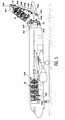
- FIG 1 there is shown schematically an embodiment of the device of the invention which essentially comprises a rangefinder 6 with laser beam 8, connected to a data processing system 4.
- This rangefinder 6 is used, as will be seen below in detail, to locate, by virtue of its beam, landmarks on an aircraft 2; these points then make it possible to precisely position, delimitation means and in particular masks, strips or stencils delimiting the desired decoration which is carried out for example by applying one or more paints of different colors in areas thus delimited.
- the rangefinder used is of known type, and will not be described in detail. It includes in particular a magnifying telescope (not shown in the figure) making it possible to aim for the initial setting of the range finder with respect to reference marks linked to the aircraft. It is this calibration which then makes it possible to carry out with precision the projection onto the plane of the layout of the decoration or of characteristic points of location of this layout.
- the laser source of the range finder emits a laser beam 8 whose impact on the aircraft is a characteristic point on the layout of the decoration.
- the coordinates of each characteristic point have been determined by the processing system 4 using data from C.A.O. These coordinates are determined in a reference frame. The coordinates are saved in a memory of the processing system.
- the processing system 4 will not be described here in detail. It includes for example a microcomputer with screen and control keyboard. Other embodiments of the device of the invention will be described later in detail.
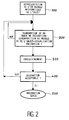
- FIG. 2 is a flowchart showing the essential steps of the method of the invention. Details of these essential steps will be given later.
- This method includes a step 100 which consists of composing a 3D computer file defining a mathematical or virtual model of the aircraft to be decorated.
- the data in this file is established from software specialized qualified as "surface” or “volume”, because relating to the surface or the volume of the object.
- This software is marketed, for example, under the AEROLLS or CATIA brands.
- This file must also contain location reference data in order to correctly define the layout of the decoration and its positioning on the aircraft.
- the 3D model definition file of the aircraft to be decorated can be made up of files from different partners who participated in the definition and construction of the aircraft. It can also be established by geometric measurements on the airplane, for example using a meter, or by photogrammetry.
- the next step 200 consists in developing a 3D mathematical model of the layout of the decoration, using specialized software which may be one of the software mentioned above.
- Images of the decorated aircraft can then be obtained by computer on the display screen of the processing system 4 (FIG. 1).
- This display operation is a simulation of the image of the decorated aircraft.
- step 200 After validation by the airline, the data for this model of the layout of the decoration are frozen in a file which gives a precise definition of the decoration in three dimensions. Obtaining this 3D file of a decoration model will be described later in detail.
- the 3D file of a decoration model having been established, step 200 then consists in superimposing the 3D model of the decoration layout, on the 3D model of the aircraft to be decorated. This superposition uses in particular the positioning reference data contained in the 3D file of the model the plane.
- the file obtained is then a 3D file of the decorated aircraft.
- obtaining a 3D decoration file can be the result of processing a 2D decoration file represented in a plan.
- C.A.O. (3D) surface or volume do not allow direct modification of the plot of a curve obtained in C.A.O., on a surface, also, obtained in C.A.O.
- the airline defined the decoration in a 2D plan. This definition is not entirely satisfactory because it is given in a plan and is not the result of projections. It is therefore not certain that the layout of the decoration on the aircraft corresponds well to the wishes of the airline.
- the projection method which has just been described can therefore give a result which the representative of the airline company does not appreciate exactly when the decoration is implemented in full size on the plane.
- step 200 may include two additional operations.
- One of these operations consists in using software, for example known under the brand CDRS, which allows you to manipulate curves attached to surfaces. Thanks to this type of software, it is possible to optimize the projection of curves on surfaces, by visual control, from predetermined projection points. This optimization makes it possible to ensure the harmonization and visual continuity of the curves on the highly evolving parts of the surface of the aircraft, and especially on the interfaces between different evolving parts or between evolving parts and plane parts (for example , the rear cone of the airplane, the fin, the front point, etc.).
- This development of the visualization of the decorated aircraft image can be improved at any time by the use of computer graphics which allow a realistic presentation of the decorated aircraft to the airline.
- This file contains data relating to the surfaces of the aircraft, the layout of the decoration, and in particular data corresponding to the relative positions of the layout and the surface.
- the recording is not carried out and the layout can be modified, as described above.
- the computer file may also contain positioning data relating to the location of doors, portholes, seals, air intakes and other elements visible on the aircraft.
- the data thus recorded in the computer file are essentially coordinates of points on the decoration layout and points on the plane's surface, measured in the same reference frame, linked to the plane.
- the next step 400 consists, by means which will be described later in detail, of carrying out a first prototype decoration on an aircraft, using the positioning and delimitation data of the decoration, contained in the computer file created in step 300. If this real decoration is accepted (YES answer to question 400), the data in the file are validated and can be used for the decoration of a series of planes of the same type belonging to the airline concerned (step 500). If the actual decoration is not accepted (answer NO to question 400), it is necessary to modify the content of the file, returning to step 200. The data relating to the modifications, resulting from retouching of the decoration prototype on the real plane, are of course modified to update the file.
- step 200 The creation of the computer file (step 200) containing the data relating to the 3D models of the surface of the aircraft and of the layout of the decoration, will now be described in more detail.
- the creation of the 3D decoration file in step 200 includes a preliminary phase of design or definition of the decoration.
- the definition of decoration can be established either at from a drawing or a layout of the decoration in a plan, in two dimensions (by CAD (2D) for example), or by computer generated images. Whatever the mode of definition chosen, each of them serves as a basis for the validation of the decoration by the airline.
- a paper support is used.
- This plan can also be obtained at the output of a printer connected to a processing system by C.A.O.
- Several planes may be necessary to represent front, side, bottom, etc. views of the decorated aircraft. Additional information is added, for example dimensions, color references, etc.
- the decoration is defined by C.A.O.
- software makes it possible to obtain computer-generated images, from all angles, of an undecorated aircraft.
- the operator can directly represent the decoration curves on the plane's surface: tracing strips, using patterns from a library or obtained by any other acquisition process (scanner, photo, video, etc.) .
- the software can also make it possible to carry out projections of the decoration in relation to fictitious aiming points qualified as control points, from which the decoration patterns must have a predefined appearance.
- the decoration paint is applied to an airplane which is a relief support, and the 3D file is essential to order precise decoration tools. This tool makes it possible to faithfully reproduce the chosen decoration and avoids drawing errors due to the painter's interpretation of 2D plans with insufficient information.
- this decoration can be used as a model for other planes of the same type from the same company. It is then possible to use photogrammetry or 3D measurement by theodolite to take readings making it possible to constitute the 3D file of the decoration. Photogrammetry uses photographs of targets stuck on the plane, while theodolite measurement uses intersections of sights.
- the essential advantage of this method is that the 3D decoration file corresponds to the requirements of the airline company since it comes from an aircraft that is actually decorated and validated.
- the production of a prototype decoration on a real aircraft can then be carried out, for example in the following manner: the characteristic points of the layout of the decoration are projected onto the surface of the aircraft by optical means.
- the coordinates of these characteristic points have been stored, as described above, in the computer file. This projection is carried out for example using the laser rangefinder 6 of FIG. 1, after initial setting with the aid of the telescopic sight, as indicated above.
- the coordinates of the characteristic points determined and recorded by the processing system 4 can be, according to a procedure of the method, read on a screen of the processing system. These coordinates can also be saved in a memory specific to the rangefinder. In this operating mode, an operator located near the laser range finder 6 orients the range finder manually using incorporated adjustment means so that the impact of the range finder's beam on the aircraft is a point whose coordinates correspond to those which are read on the screen and which correspond to a characteristic point of the plot.
- the aiming is automatic.
- the range finder then comprises means for controlling the movement and orientation of the light source, connected to the processing system. These means control the automatic orientation of the laser beam so that it is directed towards the characteristic points of the layout which must be located on the aircraft.
- the displacement and orientation control means are known in the state of the art and are not shown in FIG. 1.
- Each point of impact of the rangefinder beam on the aircraft can be selected by the operator, for example using a remote control to indicate the number of the point that it is desirable to view.
- each light projection is limited to areas of successive work, of relatively small dimensions, which can be assimilated to non-deformed areas.
- the operator For each work area, the operator identifies the characteristic points on the plane of the decoration one by one. The identification of these points makes it possible to position a mask or pre-cut adhesives delimiting the letters, distinctive signs, logos, etc. constituting the decoration.
- the decoration of the aircraft is carried out by painting the decoration areas thus delimited.
- the decoration of a first aircraft being completed, it is subject to the approval of the airline. If the decoration of the first aircraft is accepted, the other aircraft of the same type of the airline can then be decorated in series according to the same process using the data already stored in the computer file. Otherwise, the process is repeated, as indicated above in step 200, taking into account the modifications desired by the airline. This case is however unlikely since the layout of the decoration has been previously approved and it is hardly conceivable that the effect of the decoration obtained by viewing on the screen of a processing system is different from the actual effect. got on the plane.
- FIG. 5 examples of the drawing of decorations on an airplane have been shown.
- Several possibilities are offered, according to the invention, for delimiting and obtaining a decoration on the fuselage of the aircraft.
- the first consists in identifying characteristic points by adhesive indexes or erasable marks 10A, 10B, 10C, 10D and 10E. These points characteristics are then connected by a strip or an adhesive tape 10 in order to obtain a line of delimitation of the decoration.
- This possibility is mainly used when the decoration only includes decorative strips or decorative figures of simple shapes.
- this decoration delimitation line can also be used as a marking line to position a delimitation cover for the decoration paint, this cover being fixed by the adhesive strip 10.
- Another possibility is to apply a decorative sticker 12 whose location is determined by adhesive indexes 12A, 12B, 12C, 12D positioned using the rangefinder.
- the self-adhesive elements can be in pre-cut form. They represent for example the complex attributes identifying the airline company (letters, logotypes, etc.), technical markings, etc.
- Another possibility consists in locating a stencil 14 thanks to adhesive indexes 14A, 14B, 14C whose positions are identified using the rangefinder. The location of this stencil is carried out after prior positioning of a 14D adhesive strip.
- the device of the invention further comprises a means 9 for projecting images of the decoration, coupled to the rangefinder 6 ( Figure 1).
- This projection means can be of the video type. He projects a full-size image of the decoration onto the plane. This image is obtained from the data relating to the synthetic image of the decoration, recorded in the computer file described more high. The position and the direction of projection of the image of the decoration in real size on the plane, are determined by means of a laser rangefinder. In order to limit the distortion of the projected image of the decoration on the aircraft, in particular on surfaces of evolving shapes, the projection can be carried out according to successive portions of images of the decoration.
- the projected image of the decoration allows, for example, to trace the contours of this decoration on the plane.
- the above-mentioned adhesive tapes, bands, indexes or stencils can also be applied by a robot with a manipulating arm.
- the movement of the robot around the aircraft as well as the positions of the arm are located relative to a reference frame linked to the aircraft and are controlled by the processing system from the data recorded in the computer file.
- the robot can also deposit a masking film delimiting the areas to be painted.
- This film can be made of an adhesive polymer material delivered by a distributor, the flow rate of which is quantified so that the polymerization takes place as the distributor advances.
- a "peelable" mask consisting of a sensitive layer adhering to the object, cut by laser beam adapted to this function, guided by the range finder, so as to delimit the layout of the decoration.
- the cutting of the sensitive layer makes it possible to remove the zones of sensitive layers corresponding to the zones to be painted to obtain the decoration, while leaving in place the protective sensitive zone which allows the application of the paint.
- the protective layer is then removed when the paint drying cycle is complete.
Landscapes
- Engineering & Computer Science (AREA)
- Physics & Mathematics (AREA)
- Geometry (AREA)
- General Physics & Mathematics (AREA)
- Theoretical Computer Science (AREA)
- Aviation & Aerospace Engineering (AREA)
- Software Systems (AREA)
- Automation & Control Theory (AREA)
- Computer Graphics (AREA)
- Computational Mathematics (AREA)
- Mathematical Analysis (AREA)
- Mathematical Optimization (AREA)
- Pure & Applied Mathematics (AREA)
- Computer Hardware Design (AREA)
- Evolutionary Computation (AREA)
- General Engineering & Computer Science (AREA)
- Processing Or Creating Images (AREA)
- Toys (AREA)
Applications Claiming Priority (2)
| Application Number | Priority Date | Filing Date | Title |
|---|---|---|---|
| FR9212146 | 1992-10-12 | ||
| FR9212146A FR2696685B1 (fr) | 1992-10-12 | 1992-10-12 | Procédé et dispositif d'aide à la décoration d'un objet tridimensionnel. |
Publications (2)
| Publication Number | Publication Date |
|---|---|
| EP0593340A1 true EP0593340A1 (de) | 1994-04-20 |
| EP0593340B1 EP0593340B1 (de) | 2002-03-27 |
Family
ID=9434420
Family Applications (1)
| Application Number | Title | Priority Date | Filing Date |
|---|---|---|---|
| EP93402470A Expired - Lifetime EP0593340B1 (de) | 1992-10-12 | 1993-10-07 | Verfahren und Vorrichtung zur Erleichterung der Dekoration eines dreidimensionalen Gegenstandes |
Country Status (5)
| Country | Link |
|---|---|
| US (1) | US5490080A (de) |
| EP (1) | EP0593340B1 (de) |
| DE (1) | DE69331756T2 (de) |
| ES (1) | ES2173885T3 (de) |
| FR (1) | FR2696685B1 (de) |
Cited By (6)
| Publication number | Priority date | Publication date | Assignee | Title |
|---|---|---|---|---|
| WO1996039310A1 (en) * | 1995-06-06 | 1996-12-12 | The Boeing Company | Appliques for surfaces having complex curvature |
| FR2887492A1 (fr) * | 2005-06-28 | 2006-12-29 | Soc D Peintures Monumentales S | Procede et dispositif pour realiser des decorations monumentales |
| FR2891195A1 (fr) * | 2005-09-26 | 2007-03-30 | Soc D Peintures Monumentales S | Procede et dispositif pour realiser des decorations monumentales. |
| WO2007000468A3 (fr) * | 2005-06-28 | 2007-06-07 | Soc D Peintures Monumentales S | Procede et dispositif pour realiser des decorations monumentales |
| FR2907246A1 (fr) * | 2006-10-12 | 2008-04-18 | Airbus France Sas | Procede et dispositifs de projection de motifs bidimensionels sur des surfaces complexes d'objets tridimensionnels |
| RU2745686C1 (ru) * | 2020-06-23 | 2021-03-30 | Общество с ограниченной ответственностью "ВУД ЭНД ЛЭЗЕР ТЕХНОЛОДЖИС" | Система позиционирования |
Families Citing this family (18)
| Publication number | Priority date | Publication date | Assignee | Title |
|---|---|---|---|---|
| US6415050B1 (en) | 1996-09-03 | 2002-07-02 | Christian Stegmann | Method for displaying an object design |
| US6073056A (en) * | 1997-04-08 | 2000-06-06 | Larry J. Winget | Method and system for building a data model of a physical part in a data format useful for and reproduction of the part |
| US6460266B1 (en) | 1999-10-27 | 2002-10-08 | J. L. Clark, Inc. | Graphical design aid and method of providing visual guides on keyline design drawings |
| US6344853B1 (en) * | 2000-01-06 | 2002-02-05 | Alcone Marketing Group | Method and apparatus for selecting, modifying and superimposing one image on another |
| US6673281B1 (en) | 2001-02-05 | 2004-01-06 | Graham Packaging Company, L.P. | Method of designing and manufacturing a plastic blow-molded container |
| FR2829899B1 (fr) * | 2001-09-17 | 2004-02-20 | Franck Maurence | Procede et dispositif de reproduction de motifs sur un support |
| AU2003243361A1 (en) * | 2002-05-31 | 2003-12-19 | Graham Packaging Company, L.P. | Method for creating a sculpture on a container |
| US20040220690A1 (en) * | 2003-05-02 | 2004-11-04 | Graham Packaging Company, L.P. | Method and apparatus for creating textured handle packaging |
| US7430456B2 (en) * | 2006-02-08 | 2008-09-30 | Seagate Technology Llc | Reference point teaching using an end effector to form a witness mark |
| US20080282166A1 (en) * | 2007-04-24 | 2008-11-13 | Scott Robert Fillman | Method and system for designing a pastry |
| DE102007063376A1 (de) | 2007-12-30 | 2009-07-02 | Lübeck, Felix | Anstreichhilfe |
| US20100076731A1 (en) * | 2008-04-24 | 2010-03-25 | Topplestone, Llc | Method and system for designing a pastry |
| GB0908052D0 (en) * | 2009-05-11 | 2009-06-24 | Leaman Browne Ltd | Preparation of coverings |
| DE102009058802B4 (de) * | 2009-12-18 | 2018-03-29 | Airbus Operations Gmbh | Anordnung zur kombinierten Darstellung eines realen und eines virtuellen Modells |
| US9519396B2 (en) | 2010-09-28 | 2016-12-13 | Apple Inc. | Systems, methods, and computer-readable media for placing an asset on a three-dimensional model |
| IN2013KO01115A (de) * | 2013-09-27 | 2015-04-03 | 3M Innovative Properties Co | |
| DE102017101524A1 (de) | 2017-01-26 | 2018-07-26 | Bruvis Multi Media Creative Co., Ltd. | Projektionsmapping-Verfahren |
| CN108031588A (zh) * | 2017-12-29 | 2018-05-15 | 深圳海桐防务装备技术有限责任公司 | 自动喷涂装置及使用其的自动喷涂方法 |
Citations (4)
| Publication number | Priority date | Publication date | Assignee | Title |
|---|---|---|---|---|
| EP0198630A2 (de) * | 1985-04-03 | 1986-10-22 | Sony Corporation | Verfahren und System zur Bildveränderung |
| EP0290809A2 (de) * | 1987-04-14 | 1988-11-17 | Northrop Grumman Corporation | Herstellungssystem unter Verwendung von dreidimensionalen graphischen Modellen |
| EP0371897A1 (de) * | 1988-12-01 | 1990-06-06 | Cebal | Verfahren zur Dekoration eines konformierbaren Modells, Anwendung dieses Verfahrens und damit hergestellte Produkte |
| EP0431239A1 (de) * | 1989-11-17 | 1991-06-12 | Patrick W. Marsek | Verfahren zum flüssigen Sprühauftrag |
Family Cites Families (5)
| Publication number | Priority date | Publication date | Assignee | Title |
|---|---|---|---|---|
| US4469022A (en) * | 1983-04-01 | 1984-09-04 | Permanent Label Corporation | Apparatus and method for decorating articles of non-circular cross-section |
| GB8626499D0 (en) * | 1986-11-06 | 1986-12-10 | Busm Co Ltd | Treating workpieces |
| US4937768A (en) * | 1987-04-14 | 1990-06-26 | Northrop Corporation | Integrated assembly system |
| US4845634A (en) * | 1987-07-29 | 1989-07-04 | Westinghouse Electric Corp. | Product information network system |
| US4845635A (en) * | 1987-08-28 | 1989-07-04 | Rosselli Richard A | Computer controlled apparatus for imparting a design onto the surface of a candle |
-
1992
- 1992-10-12 FR FR9212146A patent/FR2696685B1/fr not_active Expired - Lifetime
-
1993
- 1993-10-07 ES ES93402470T patent/ES2173885T3/es not_active Expired - Lifetime
- 1993-10-07 DE DE69331756T patent/DE69331756T2/de not_active Expired - Lifetime
- 1993-10-07 EP EP93402470A patent/EP0593340B1/de not_active Expired - Lifetime
- 1993-10-08 US US08/134,203 patent/US5490080A/en not_active Expired - Lifetime
Patent Citations (4)
| Publication number | Priority date | Publication date | Assignee | Title |
|---|---|---|---|---|
| EP0198630A2 (de) * | 1985-04-03 | 1986-10-22 | Sony Corporation | Verfahren und System zur Bildveränderung |
| EP0290809A2 (de) * | 1987-04-14 | 1988-11-17 | Northrop Grumman Corporation | Herstellungssystem unter Verwendung von dreidimensionalen graphischen Modellen |
| EP0371897A1 (de) * | 1988-12-01 | 1990-06-06 | Cebal | Verfahren zur Dekoration eines konformierbaren Modells, Anwendung dieses Verfahrens und damit hergestellte Produkte |
| EP0431239A1 (de) * | 1989-11-17 | 1991-06-12 | Patrick W. Marsek | Verfahren zum flüssigen Sprühauftrag |
Non-Patent Citations (1)
| Title |
|---|
| B. K. HINDS ET. AL.: "PATTERN DEVELOPMENT FOR 3D SURFACES", COMPUTER-AIDED DESIGN, vol. 23, no. 8, October 1991 (1991-10-01), LONDON, GB, pages 583 - 592, XP000236521 * |
Cited By (10)
| Publication number | Priority date | Publication date | Assignee | Title |
|---|---|---|---|---|
| WO1996039310A1 (en) * | 1995-06-06 | 1996-12-12 | The Boeing Company | Appliques for surfaces having complex curvature |
| FR2887492A1 (fr) * | 2005-06-28 | 2006-12-29 | Soc D Peintures Monumentales S | Procede et dispositif pour realiser des decorations monumentales |
| WO2007000468A3 (fr) * | 2005-06-28 | 2007-06-07 | Soc D Peintures Monumentales S | Procede et dispositif pour realiser des decorations monumentales |
| FR2891195A1 (fr) * | 2005-09-26 | 2007-03-30 | Soc D Peintures Monumentales S | Procede et dispositif pour realiser des decorations monumentales. |
| FR2907246A1 (fr) * | 2006-10-12 | 2008-04-18 | Airbus France Sas | Procede et dispositifs de projection de motifs bidimensionels sur des surfaces complexes d'objets tridimensionnels |
| WO2008043919A3 (fr) * | 2006-10-12 | 2008-07-17 | Airbus France | Procede et dispositifs de projection de motifs bidimensionnels sur des surfaces complexes d'objets tridimensionnels |
| JP2010506320A (ja) * | 2006-10-12 | 2010-02-25 | エアバス フランス | 3次元オブジェクトの複雑な表面上へ2次元モチーフを投影する投影装置と投影方法 |
| RU2433920C2 (ru) * | 2006-10-12 | 2011-11-20 | Эрбюс Операсьон (Сас) | Способ и устройство для проецирования двухмерных рисунков на сложные поверхности трехмерных объектов |
| US8614711B2 (en) | 2006-10-12 | 2013-12-24 | Airbus Operations Sas | Method and devices for projecting two-dimensional patterns onto complex surfaces of three-dimensional objects |
| RU2745686C1 (ru) * | 2020-06-23 | 2021-03-30 | Общество с ограниченной ответственностью "ВУД ЭНД ЛЭЗЕР ТЕХНОЛОДЖИС" | Система позиционирования |
Also Published As
| Publication number | Publication date |
|---|---|
| DE69331756D1 (de) | 2002-05-02 |
| FR2696685A1 (fr) | 1994-04-15 |
| EP0593340B1 (de) | 2002-03-27 |
| FR2696685B1 (fr) | 1994-12-23 |
| ES2173885T3 (es) | 2002-11-01 |
| DE69331756T2 (de) | 2002-11-21 |
| US5490080A (en) | 1996-02-06 |
Similar Documents
| Publication | Publication Date | Title |
|---|---|---|
| EP0593340B1 (de) | Verfahren und Vorrichtung zur Erleichterung der Dekoration eines dreidimensionalen Gegenstandes | |
| US20240020430A1 (en) | System and method for authoring high quality renderings and generating manufacturing output of custom products | |
| EP2097274B1 (de) | Verfahren und vorrichtung zur projektion zweidimensionaler muster auf komplexe oberflächen dreidimensionaler objekte | |
| US12056343B2 (en) | System and method for authoring high quality renderings and generating manufacturing output of custom products | |
| US20230385466A1 (en) | System and method for authoring high quality renderings and generating manufacturing output of custom products | |
| US20200004222A1 (en) | Method of simulating the rigging of a space | |
| US12159335B2 (en) | System and method for authoring high quality renderings and generating manufacturing output of custom products | |
| US20230385465A1 (en) | System and method for authoring high quality renderings and generating manufacturing output of custom products | |
| US20230385467A1 (en) | System and method for authoring high quality renderings and generating manufacturing output of custom products | |
| FR2693567A1 (fr) | Procédé et dispositif de fabrication d'éléments adhésifs destinés à être appliqués sur une surface tridimensionnelle en vue de sa décoration. | |
| US20230386196A1 (en) | System and method for authoring high quality renderings and generating manufacturing output of custom products | |
| FR2850322A1 (fr) | Dispositif d'impression d'une image sur une grande surface | |
| US4148580A (en) | Process for making shade relief maps and the map made thereby | |
| Salinas | 3D printing with RepRap cookbook | |
| EP1732042A1 (de) | Verfahren und System zur Verarbeitung geometrischer Merkmale eines digital kodierten Bildes | |
| EP1911264A2 (de) | Verfahren und vorrichtung zum tapezieren von wänden | |
| FR2891195A1 (fr) | Procede et dispositif pour realiser des decorations monumentales. | |
| Onstott | Enhancing architectural drawings and models with Photoshop | |
| CN113733234A (zh) | 标志点成型组件及标志点成型方法 | |
| Paquette | Shaders and Texturing |
Legal Events
| Date | Code | Title | Description |
|---|---|---|---|
| PUAI | Public reference made under article 153(3) epc to a published international application that has entered the european phase |
Free format text: ORIGINAL CODE: 0009012 |
|
| AK | Designated contracting states |
Kind code of ref document: A1 Designated state(s): DE ES GB IT NL |
|
| 17P | Request for examination filed |
Effective date: 19940924 |
|
| 17Q | First examination report despatched |
Effective date: 19990818 |
|
| GRAG | Despatch of communication of intention to grant |
Free format text: ORIGINAL CODE: EPIDOS AGRA |
|
| GRAG | Despatch of communication of intention to grant |
Free format text: ORIGINAL CODE: EPIDOS AGRA |
|
| GRAH | Despatch of communication of intention to grant a patent |
Free format text: ORIGINAL CODE: EPIDOS IGRA |
|
| GRAH | Despatch of communication of intention to grant a patent |
Free format text: ORIGINAL CODE: EPIDOS IGRA |
|
| REG | Reference to a national code |
Ref country code: GB Ref legal event code: IF02 |
|
| GRAA | (expected) grant |
Free format text: ORIGINAL CODE: 0009210 |
|
| AK | Designated contracting states |
Kind code of ref document: B1 Designated state(s): DE ES GB IT NL |
|
| RIC1 | Information provided on ipc code assigned before grant |
Free format text: 7G 06T 17/00 A, 7B 41M 1/40 B, 7B 44D 2/00 B |
|
| REF | Corresponds to: |
Ref document number: 69331756 Country of ref document: DE Date of ref document: 20020502 |
|
| GBT | Gb: translation of ep patent filed (gb section 77(6)(a)/1977) |
Effective date: 20020807 |
|
| REG | Reference to a national code |
Ref country code: ES Ref legal event code: FG2A Ref document number: 2173885 Country of ref document: ES Kind code of ref document: T3 |
|
| PLBE | No opposition filed within time limit |
Free format text: ORIGINAL CODE: 0009261 |
|
| STAA | Information on the status of an ep patent application or granted ep patent |
Free format text: STATUS: NO OPPOSITION FILED WITHIN TIME LIMIT |
|
| 26N | No opposition filed |
Effective date: 20021230 |
|
| PGFP | Annual fee paid to national office [announced via postgrant information from national office to epo] |
Ref country code: IT Payment date: 20091028 Year of fee payment: 17 |
|
| PGFP | Annual fee paid to national office [announced via postgrant information from national office to epo] |
Ref country code: NL Payment date: 20101013 Year of fee payment: 18 |
|
| PG25 | Lapsed in a contracting state [announced via postgrant information from national office to epo] |
Ref country code: IT Free format text: LAPSE BECAUSE OF NON-PAYMENT OF DUE FEES Effective date: 20101007 |
|
| REG | Reference to a national code |
Ref country code: NL Ref legal event code: V1 Effective date: 20120501 |
|
| PG25 | Lapsed in a contracting state [announced via postgrant information from national office to epo] |
Ref country code: NL Free format text: LAPSE BECAUSE OF NON-PAYMENT OF DUE FEES Effective date: 20120501 |
|
| PGFP | Annual fee paid to national office [announced via postgrant information from national office to epo] |
Ref country code: DE Payment date: 20121023 Year of fee payment: 20 |
|
| PGFP | Annual fee paid to national office [announced via postgrant information from national office to epo] |
Ref country code: GB Payment date: 20121019 Year of fee payment: 20 Ref country code: ES Payment date: 20121026 Year of fee payment: 20 |
|
| REG | Reference to a national code |
Ref country code: DE Ref legal event code: R071 Ref document number: 69331756 Country of ref document: DE |
|
| REG | Reference to a national code |
Ref country code: DE Ref legal event code: R071 Ref document number: 69331756 Country of ref document: DE |
|
| REG | Reference to a national code |
Ref country code: GB Ref legal event code: PE20 Expiry date: 20131006 |
|
| PG25 | Lapsed in a contracting state [announced via postgrant information from national office to epo] |
Ref country code: DE Free format text: LAPSE BECAUSE OF EXPIRATION OF PROTECTION Effective date: 20131008 Ref country code: GB Free format text: LAPSE BECAUSE OF EXPIRATION OF PROTECTION Effective date: 20131006 |
|
| REG | Reference to a national code |
Ref country code: ES Ref legal event code: FD2A Effective date: 20140307 |
|
| PG25 | Lapsed in a contracting state [announced via postgrant information from national office to epo] |
Ref country code: ES Free format text: LAPSE BECAUSE OF EXPIRATION OF PROTECTION Effective date: 20131008 |