EP0593345A1 - Elektrisches Heizgerät - Google Patents
Elektrisches Heizgerät Download PDFInfo
- Publication number
- EP0593345A1 EP0593345A1 EP93402487A EP93402487A EP0593345A1 EP 0593345 A1 EP0593345 A1 EP 0593345A1 EP 93402487 A EP93402487 A EP 93402487A EP 93402487 A EP93402487 A EP 93402487A EP 0593345 A1 EP0593345 A1 EP 0593345A1
- Authority
- EP
- European Patent Office
- Prior art keywords
- frame
- panel
- front panel
- connector
- insulating material
- Prior art date
- Legal status (The legal status is an assumption and is not a legal conclusion. Google has not performed a legal analysis and makes no representation as to the accuracy of the status listed.)
- Withdrawn
Links
- 238000005485 electric heating Methods 0.000 title claims description 3
- 230000002093 peripheral effect Effects 0.000 claims abstract description 10
- 239000012777 electrically insulating material Substances 0.000 claims abstract description 8
- 239000011810 insulating material Substances 0.000 claims abstract description 6
- 238000007789 sealing Methods 0.000 claims description 9
- 239000011521 glass Substances 0.000 claims description 3
- 239000000126 substance Substances 0.000 claims description 2
- 229920002994 synthetic fiber Polymers 0.000 claims description 2
- 238000004026 adhesive bonding Methods 0.000 abstract description 2
- 239000002390 adhesive tape Substances 0.000 description 8
- 238000004519 manufacturing process Methods 0.000 description 6
- 238000010438 heat treatment Methods 0.000 description 5
- 210000002105 tongue Anatomy 0.000 description 4
- 239000000853 adhesive Substances 0.000 description 3
- 230000001070 adhesive effect Effects 0.000 description 3
- 239000004020 conductor Substances 0.000 description 3
- 238000010292 electrical insulation Methods 0.000 description 3
- 238000009413 insulation Methods 0.000 description 3
- 229920002614 Polyether block amide Polymers 0.000 description 2
- 238000001514 detection method Methods 0.000 description 2
- 239000003292 glue Substances 0.000 description 2
- 239000000463 material Substances 0.000 description 2
- XLYOFNOQVPJJNP-UHFFFAOYSA-N water Substances O XLYOFNOQVPJJNP-UHFFFAOYSA-N 0.000 description 2
- 206010014405 Electrocution Diseases 0.000 description 1
- 229920000877 Melamine resin Polymers 0.000 description 1
- 240000008042 Zea mays Species 0.000 description 1
- 230000002159 abnormal effect Effects 0.000 description 1
- XAGFODPZIPBFFR-UHFFFAOYSA-N aluminium Chemical compound [Al] XAGFODPZIPBFFR-UHFFFAOYSA-N 0.000 description 1
- 229910052782 aluminium Inorganic materials 0.000 description 1
- 230000000712 assembly Effects 0.000 description 1
- 238000000429 assembly Methods 0.000 description 1
- 210000003323 beak Anatomy 0.000 description 1
- 239000003990 capacitor Substances 0.000 description 1
- 230000008878 coupling Effects 0.000 description 1
- 238000010168 coupling process Methods 0.000 description 1
- 238000005859 coupling reaction Methods 0.000 description 1
- 238000009826 distribution Methods 0.000 description 1
- 230000000694 effects Effects 0.000 description 1
- 229940082150 encore Drugs 0.000 description 1
- 229920002457 flexible plastic Polymers 0.000 description 1
- 239000003365 glass fiber Substances 0.000 description 1
- 238000000265 homogenisation Methods 0.000 description 1
- JDSHMPZPIAZGSV-UHFFFAOYSA-N melamine Chemical compound NC1=NC(N)=NC(N)=N1 JDSHMPZPIAZGSV-UHFFFAOYSA-N 0.000 description 1
- 239000000203 mixture Substances 0.000 description 1
- 239000000615 nonconductor Substances 0.000 description 1
- 230000035515 penetration Effects 0.000 description 1
- 229920003023 plastic Polymers 0.000 description 1
- 239000004033 plastic Substances 0.000 description 1
- 229920000728 polyester Polymers 0.000 description 1
- 239000004800 polyvinyl chloride Substances 0.000 description 1
- 230000000284 resting effect Effects 0.000 description 1
- 125000006850 spacer group Chemical group 0.000 description 1
- 238000003466 welding Methods 0.000 description 1
Images


Classifications
-
- F—MECHANICAL ENGINEERING; LIGHTING; HEATING; WEAPONS; BLASTING
- F24—HEATING; RANGES; VENTILATING
- F24C—DOMESTIC STOVES OR RANGES ; DETAILS OF DOMESTIC STOVES OR RANGES, OF GENERAL APPLICATION
- F24C7/00—Stoves or ranges heated by electric energy
- F24C7/04—Stoves or ranges heated by electric energy with heat radiated directly from the heating element
- F24C7/043—Stoves
Definitions
- the invention relates to an electric heater of the radiant type.
- the invention aims to improve such a heating device, in particular with regard to its manufacture, its performance and its safety in use.
- an electric heating device comprising a front panel, an electrical resistant means disposed on a rear face of the front panel, a rear panel and a peripheral frame on which said front and rear panels are fixed respectively on a front surface and on a rear surface which are parallel to each other and offset in depth with respect to each other, thus trapping an air space
- the panel rear is made of thermally insulating material
- the front and rear panels and the peripheral frame are at least externally made of electrically insulating material and in that the front and rear panels are fixed to the frame by bonding continued.
- the frame allows to form, thanks to its cooperation by continuous bonding with the front and rear panels, a hermetic enclosure which traps a space internal air to the device.
- This air space which is located between the resistant means and the rear panel, perfects the thermal insulation which the latter provides, which is advantageous in terms of performance.
- this airtight enclosure protects the means of electrical resistance to splashing water, and consequently of undesirable effects which could result from it, in particular when it comes to the safe use of the device.
- the hermetic enclosure also provides electrical insulation of the resistant means from the outside.
- the means resistant which is conductive and has a certain surface
- the front panel is a mirror formed by a glass plate on the rear face of which a reflective layer is deposited.
- the rear surface is offset with respect to the front surface both in depth towards the rear and in width inwards, and said front and rear surfaces each look towards the front.
- This characteristic is advantageous from the manufacturing point of view, because it allows, without having to turn the frame over, to bond the rear insulating panel to it, then the front panel.
- the frame comprises between said front and rear surfaces an orifice through which passes an electrical supply means of the resistant means, sealing and fixing means being provided between the frame and the supply means. Thanks to the sealing means, the hermetic nature of the enclosure is not disturbed by the penetration into it of the supply of the electrical resistant means.
- the passage orifice is formed in the frame between the front and rear surfaces, which is possible thanks to the offset provided between them, any orifice and therefore any fixing of the supply both on the front panel - which is undesirable for aesthetic reasons - only on the rear panel, which may not have sufficient tear resistance, the insulating materials from the thermal point of view being generally soft or brittle.
- connection between the supply means and the electrical resistance means can be made by simple contact with a finger which is arranged parallel in the orifice, and therefore transversely to the rear face of the front panel where the electric resistant means, and which is fixed to the frame so as to be held against the resistant means.
- said electrical supply means comprises a cable at the end of which is a connector comprising a body of electrically insulating material and, for each pole, a conductive finger of which a free end projects in relation to the body, the connector being adapted to be fixed to the frame with each finger held transversely to the rear face of the front panel, in contact with a connection point provided in said electrical resistant means, and with the body which ensures a hermetic sealing of said orifice.
- connection of the supply means to the electrical resistance means and the sealing of the closure of its passage orifice are thus made at the same time, by simple fixing, preferably removable, of the connector on the frame. It is thus possible to change the supply means if desired, for example to put a longer cable or to replace a damaged cable.
- the frame is provided with means for fixing the device which comprise, on a rear side of the frame, sliding mounting means for at least one fixing member, which thus makes it possible to choose or adjust the location of the fastener (s)
- the sliding mounting means comprise a U-shaped channel with a tongue on each inner blank, said fixing member being a nut of parallelepiped shape with each side a groove corresponding to said tongue; possibly additionally, the orifice for the passage of the supply means is formed in the bottom of the U-shaped channel, said connector being fixed by means of nuts, for example with a stirrup disposed above the connector cooperating at each end with a screw engaged in one of these nuts.
- the frame has a side border for each of said front and rear panels.
- the resistive means comprises a supply network comprising two temperature limiting circuit breakers, arranged along a diagonal connecting two corners of the front panel, each temperature limiter being distant from one of these corners of a quarter of the length of the diagonal. This arrangement is particularly suitable for the detection of any abnormal rise in temperature in the device.
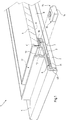
- the heating appliance 1 illustrated in FIGS. 1 to 6, comprises, as front panel, a mirror 2 on the rear face of which is disposed an electrical resistant means 3, behind which is provided a rear panel 4 of thermally insulating material, the mirror 2 and the rear insulating panel 4 being fixed to a peripheral frame 5 by continuous bonding respectively to a front surface 6 and to a rear surface 7 which are parallel to one another and offset in depth with respect to each other.
- a hermetic enclosure is formed which traps an air space 8 internal to the device, which perfects the thermal insulation of the resistant means. electric 3 towards the rear and optimizes the homogenization of the heat distribution.
- the rear insulating panel 4 is here formed by a mixture of glass fibers and melamine known under the commercial name of STRATIGLASS, coated on its internal face with an aluminum film 9 for sealing and thermal reflection.
- the continuous bonding of the mirror 2 and of the rear insulating panel 4 on the peripheral frame 5 is done using respective cords 10 and 11 of double-sided adhesive tape, and more precisely here of a tape which is adhesive in the mass (and not which has a central flexible sheet on each side of which is disposed a layer of adhesive), which makes it possible to glue each section of tape with those which are arranged perpendicularly to it, in the corners at the level of their mitered assembly, so that there is no rupture of hermeticism of the interior enclosure of the apparatus at the level of these assemblies.
- Box 5 is made of synthetic material, and more precisely here of polyvinyl chloride (PVC). It is made from sections of a profile assembled here at the tab in the corners by welding or gluing.
- PVC polyvinyl chloride
- the frame 5 comprises a channel 12 with a U-section with a tongue 13 on each inner blank to allow sliding mounting of a fixing nut 14 of parallelepipedal shape having on each side a groove 15 corresponding to the tongues 13, the top of these and the nut 14 here being at the same level so that the grooves 15 are open.
- the nuts 14 are placed in the channel 12 for each section before they are assembled to form the frame 5.
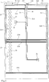
- the electrical resistant means 3 comprises two elements 20 and 21 of resistive film which are each formed by two thin sheets of insulating material, here polyester, enclosing two conductive strips 22A and 22B disposed along opposite edges, and a plurality of resistors 23 disposed between the conductive strips 22A and 22B, only two resistors 23 having been drawn for clarity of the drawing.
- the elements 20 and 21 are bonded to the rear face of the mirror 2.
- the electrical resistant means also comprises a supply network for the elements 20 and 21 formed by conductive strips 24A and 24B connected respectively to the conductive strips 22A and 22B of the elements 20 and 21, and glued with electrically insulating tape 25 which covers them.
- the supply network further comprises two temperature limiting circuit breakers 26, arranged in series in the supply of the conductors 22A. These circuit breakers are here of the bimetallic strip type, which open in the event that the temperature to which they are subjected is greater than a predetermined value.
- circuit breakers 26 are arranged along a diagonal which connects the corners located at the top left and bottom right in FIG. 3, each at a distance from one of these corners equal to a quarter of the length of the diagonal.
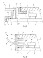
- an orifice 28 for the passage of an electrical supply means is made in the bottom of the channel 12 (see FIGS. 4 and 5).
- the orifice 28 is disposed between the front surface 6 and the rear surface 7 with respect to which it is oriented transversely, the surface 7 being offset with respect to the surface 6 both in depth towards the rear and in width towards the interior.
- the electrical supply means of the resistive means 3 comprises a cable 30 at the end of which is a connector 31 comprising a body 32 of electrically insulating material, and for each pole a conductive finger 33A or 33B of which a free end is in relation to to the body 32.
- a connector 31 comprising a body 32 of electrically insulating material, and for each pole a conductive finger 33A or 33B of which a free end is in relation to to the body 32.
- the connector 32 is here made of flexible plastic material such as polyether block amide (PEBA), in which the fingers 33A and 33B are embedded, as well as the end of the cable 30 and the connection made between the strands thereof and the fingers 33A and 33B.
- PEBA polyether block amide
- a small shoulder 34 is formed on the periphery of the body 32 in order to cooperate with the periphery of the orifice 28, in a sealed manner thanks to the flexible nature of the material of the body 32.
- Each finger 33A and 33B is surrounded by a tubular flange 35 which is crushed on the adhesive tape 25 around the respective connection points 27A and 27B, which ensures the electrical insulation of these points on the interior side of the device 1.
- the panels 2 and 4 are at least externally made of electrically insulating material, and the same is true for the frame 5 and the adhesive tapes 10 and 11, there is a second insulating protection around the conductive parts internal to the device, that is to say that it meets the conditions known as "double insulation".
- the connector 31 is held in place on the frame 5 by a stirrup 36 which covers it, cooperating at each end with a screw 37 engaged in a nut 14.
- a stirrup 36 which covers it, cooperating at each end with a screw 37 engaged in a nut 14.
- the above the body 32 is provided with two elastic flared collars 38.
- the frame 5 has a lateral border for each of the panels 2 and 4, respectively 40 and 41, this latter border being formed by the wall which delimits the internal blank of channel 12.
- the heating appliance is similar to appliance 1, with the exception of frame 5 which is replaced by frame 5 ′ shown in section in FIG. 7 , and of the body 32 'of the connector 31'.
- the frame 5 ' is similar to the frame 5, but the surface 7 has been replaced by the surface 7' which is situated at the rear end of the border 41 (and not at the front end), the surface 7 'looking towards the front in the same way as surface 6 (and not towards the rear as surface 7 does).
- the body 32 ' is similar to the body 32, but the elastic flanges 38 located under the stirrup 36 are replaced by an elastic peripheral lip 38' disposed around the tubular flange 35.
- the panel 4 is provided on its rear outer face with an electrically insulating and waterproof film 9 ′, for example made of plastic.
- the hooks 18 (see also FIG. 6) - which are of the beak type - are replaced by hooks 18 'of the hole type.
- the frame 5 has been replaced by a 5" frame and the connector 31 by a 31 "connector.
- the 5" frame does not have a U-shaped channel 12, it has a forms in stair steps between the edges 40 and 41, the orifice for the passage of the supply means being formed in a wall situated at a level different from that which carries the surface 6.
- the connector 31 '' is more rudimentary, it is simply stuck tightly in the orifice.
- the frame 5 is replaced by a frame 5' '', and the connector 31 by a connector 31 '' '.
- the edges 40 and 41 are co-planar, the profile used to form the 5' '' frame having in section roughly the shape of the letter n.
- the connector 31 '' ' comprises a simple electrical insulation and sealing sleeve which cooperates with the frame 5' '', the connection between the connector 31 '' 'and the resistant means 3 being made by strands of electric cable of which only 33B '' 'is visible in Figure 10.
- the front panel is a mirror formed by a glass plate on the rear face of which is deposited a reflective layer (not shown).
- the mirror 2 can be replaced by an enamelled sheet on its external face, by a front panel which comprises another vitreous substance on the external side, or by any other type of panel which is suitable for radiating heat.
- the invention can be carried out with numerous variants, depending on the circumstances.
Landscapes
- Engineering & Computer Science (AREA)
- Chemical & Material Sciences (AREA)
- Combustion & Propulsion (AREA)
- Mechanical Engineering (AREA)
- General Engineering & Computer Science (AREA)
- Central Heating Systems (AREA)
- Resistance Heating (AREA)
Applications Claiming Priority (2)
| Application Number | Priority Date | Filing Date | Title |
|---|---|---|---|
| FR9212150A FR2696819B1 (fr) | 1992-10-12 | 1992-10-12 | Appareil de chauffage électrique. |
| FR9212150 | 1992-10-12 |
Publications (1)
| Publication Number | Publication Date |
|---|---|
| EP0593345A1 true EP0593345A1 (de) | 1994-04-20 |
Family
ID=9434424
Family Applications (1)
| Application Number | Title | Priority Date | Filing Date |
|---|---|---|---|
| EP93402487A Withdrawn EP0593345A1 (de) | 1992-10-12 | 1993-10-08 | Elektrisches Heizgerät |
Country Status (6)
| Country | Link |
|---|---|
| EP (1) | EP0593345A1 (de) |
| CA (1) | CA2108187A1 (de) |
| FR (1) | FR2696819B1 (de) |
| MA (1) | MA23000A1 (de) |
| NO (1) | NO933650L (de) |
| TN (1) | TNSN93109A1 (de) |
Citations (3)
| Publication number | Priority date | Publication date | Assignee | Title |
|---|---|---|---|---|
| GB1485121A (en) * | 1974-09-18 | 1977-09-08 | Parry Green Ltd | Electrical heating panel |
| FR2589994A1 (fr) * | 1985-11-07 | 1987-05-15 | Mm Int France Sarl | Dispositif electrique de chauffage par rayonnement comportant une plaque formant miroir |
| FR2620800A1 (fr) * | 1987-09-22 | 1989-03-24 | Mm Int France | Dispositif de chauffage electrique par rayonnement |
-
1992
- 1992-10-12 FR FR9212150A patent/FR2696819B1/fr not_active Expired - Fee Related
-
1993
- 1993-10-08 EP EP93402487A patent/EP0593345A1/de not_active Withdrawn
- 1993-10-11 MA MA23302A patent/MA23000A1/fr unknown
- 1993-10-11 NO NO933650A patent/NO933650L/no unknown
- 1993-10-11 TN TNSN93109 patent/TNSN93109A1/fr unknown
- 1993-10-12 CA CA 2108187 patent/CA2108187A1/en not_active Abandoned
Patent Citations (3)
| Publication number | Priority date | Publication date | Assignee | Title |
|---|---|---|---|---|
| GB1485121A (en) * | 1974-09-18 | 1977-09-08 | Parry Green Ltd | Electrical heating panel |
| FR2589994A1 (fr) * | 1985-11-07 | 1987-05-15 | Mm Int France Sarl | Dispositif electrique de chauffage par rayonnement comportant une plaque formant miroir |
| FR2620800A1 (fr) * | 1987-09-22 | 1989-03-24 | Mm Int France | Dispositif de chauffage electrique par rayonnement |
Also Published As
| Publication number | Publication date |
|---|---|
| FR2696819B1 (fr) | 1995-01-13 |
| TNSN93109A1 (fr) | 1994-03-17 |
| NO933650L (no) | 1994-04-13 |
| MA23000A1 (fr) | 1994-07-01 |
| CA2108187A1 (en) | 1994-04-13 |
| NO933650D0 (no) | 1993-10-11 |
| FR2696819A1 (fr) | 1994-04-15 |
Similar Documents
| Publication | Publication Date | Title |
|---|---|---|
| EP1478291B1 (de) | Plattenelement mit beheizter fläche | |
| EP0394089B1 (de) | Elektrisch heizbare Windschutzscheibe | |
| EP1537762B1 (de) | Verbindungseinrichtung für ein flächiges element mit mehreren schichten ausgestattet mit elektrischen funktionselementen und flächiges element | |
| FR2475191A1 (fr) | Ensemble chauffant a rayonnement pour cuisinieres a plaque de cuisson lisse | |
| EP1627555B1 (de) | Mit einer geheizten schicht ausgestattetes laminiertes element | |
| EP1559296B1 (de) | Transparentes fenster mit nichttransparenter kontaktfläche für l t-bond-verbindung | |
| EP0893938B1 (de) | Beheizbare Verbundglasscheibe, insbesondere für Flugzeugcockpit | |
| BE1005038A5 (fr) | Miroir chauffant. | |
| EP0380896A1 (de) | Bügeleisensohle, hergestellt aus aneinander hartgelöteten Metallblechen | |
| EP3619479B1 (de) | Heizmodul für eine elektrische heizvorrichtung | |
| EP0829689A1 (de) | Abdichtung für Sperrungsvorrichtung für einen Lüftungskanal, insbesondere Brandschutzklappe oder Entlüftungsklappe | |
| EP0619691B2 (de) | Glasscheibe mit Anschlusselement | |
| EP0593345A1 (de) | Elektrisches Heizgerät | |
| FR2711413A1 (fr) | Elément de chauffage plat pour un appareil chauffant. | |
| EP1629697B1 (de) | Plattenelement für geschichtete erwärmung | |
| EP1004223A1 (de) | Elektrisches heizungspaneel | |
| WO2009150354A2 (fr) | Dispositif de connexion electrique d'un vitrage feuillete a un equipement hors vitrage, procede d'assemblage d'un vitrage dote d'un tel dispositif de connexion, et vitrage ainsi obtenu | |
| FR2704629A1 (fr) | Film chauffant à structure modulaire, pour chauffage par rayonnement, et dispositif pour sa connexion. | |
| FR2908262A1 (fr) | "radiateur seche-serviettes electrique en verre de type echelle" | |
| EP0568464B1 (de) | Heizgerät, insbesondere Handtuchtrockner, mit elektrischer Heizleitung | |
| FR2518712A1 (fr) | Dispositif de chauffage d'un local par rayonnement a partir du plafond de celui-ci | |
| FR2685250A1 (fr) | Procede d'incorporation d'un element de rechauffage dans une structure en materiau composite. | |
| FR2691869A1 (fr) | Elément chauffant plat et souple à connectique intégrée. | |
| EP0441748A1 (de) | Unter einem Bodenbelag verlegtes elektrisches Niederspannungsflachkabel | |
| FR2856237A1 (fr) | Structure de blindage electromagnetique. |
Legal Events
| Date | Code | Title | Description |
|---|---|---|---|
| PUAI | Public reference made under article 153(3) epc to a published international application that has entered the european phase |
Free format text: ORIGINAL CODE: 0009012 |
|
| AK | Designated contracting states |
Kind code of ref document: A1 Designated state(s): AT BE CH DE DK ES GB GR IT LI NL SE |
|
| 17P | Request for examination filed |
Effective date: 19941011 |
|
| 17Q | First examination report despatched |
Effective date: 19951012 |
|
| STAA | Information on the status of an ep patent application or granted ep patent |
Free format text: STATUS: THE APPLICATION IS DEEMED TO BE WITHDRAWN |
|
| 18D | Application deemed to be withdrawn |
Effective date: 19960223 |