EP0593361B1 - Verfahren und Vorrichtung zum Schleifen zweier stumpf aneinanderstossender Schienen - Google Patents
Verfahren und Vorrichtung zum Schleifen zweier stumpf aneinanderstossender Schienen Download PDFInfo
- Publication number
- EP0593361B1 EP0593361B1 EP93402526A EP93402526A EP0593361B1 EP 0593361 B1 EP0593361 B1 EP 0593361B1 EP 93402526 A EP93402526 A EP 93402526A EP 93402526 A EP93402526 A EP 93402526A EP 0593361 B1 EP0593361 B1 EP 0593361B1
- Authority
- EP
- European Patent Office
- Prior art keywords
- grinding
- rail
- grinding wheel
- contact
- junction
- Prior art date
- Legal status (The legal status is an assumption and is not a legal conclusion. Google has not performed a legal analysis and makes no representation as to the accuracy of the status listed.)
- Expired - Lifetime
Links
Images


Classifications
-
- E—FIXED CONSTRUCTIONS
- E01—CONSTRUCTION OF ROADS, RAILWAYS, OR BRIDGES
- E01B—PERMANENT WAY; PERMANENT-WAY TOOLS; MACHINES FOR MAKING RAILWAYS OF ALL KINDS
- E01B31/00—Working rails, sleepers, baseplates, or the like, in or on the line; Machines, tools, or auxiliary devices specially designed therefor
- E01B31/02—Working rail or other metal track components on the spot
- E01B31/12—Removing metal from rails, rail joints, or baseplates, e.g. for deburring welds, reconditioning worn rails
- E01B31/17—Removing metal from rails, rail joints, or baseplates, e.g. for deburring welds, reconditioning worn rails by grinding
Definitions
- the invention relates to a method of grinding the butt joint by welding of two elements, such as rails and a grinding machine for the implementation of this method.
- the reference setting members are formed by specific devices which are mounted on the frame of the arrangement to come into contact with the rail at an offset location, in the longitudinal direction of the rail, from the contact point of the grinding wheel. Due to the offset between the reference points and the contact points of the grinding wheel, the reference system is different from the system of grinding marks, which means that the precision of grinding is not guaranteed.
- the object of the present invention is to propose a method and an arrangement which overcomes the major drawback of the state of the art, which has just been described.
- the method according to the invention is characterized in that the grinding wheel itself is used as reference setting members and puts it first of all in contact with the rail on one side of the junction then on the other and stores the data defining these contact points as reference values.
- the grinding machine according to the invention of the type comprising a grinding wheel carried by a grinding wheel carriage movable axially along a beam, the latter being pivotally mounted at its ends on a device capable of making an angular movement around the rail, is characterized in that the grinding wheel constitutes the member for establishing reference points for grinding and that a programmable controller is provided for establishing from the points reference data allowing automatic grinding of the area to be ground.
- Figure 1 is a perspective and schematic view of a first embodiment of a grinding machine according to the present invention.
- FIG. 2 is a sectional view, on a larger scale and with parts broken away, of the detail indicated by the circle II of FIG. 1.
- FIGS 3a to 3d illustrate the progress of the grinding process according to the invention by showing four significant steps of this process.
- Figure 4 is a schematic sectional view along the line IV-IV of Figure 1, but shows only the grinding wheel in the state applied to the rail.
- FIG. 5 is a side view of a concrete embodiment of the structure of the support beam of the grinding wheel, of FIG. 1.
- FIG. 6 is a top view of the support beam of FIG. 4.
- FIG. 7 is a view in the direction of arrow VII of FIG. 5.
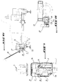
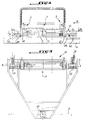
- Figure 8 is a side view of a second embodiment of a grinding machine according to the present invention.
- FIG. 9 is a top view of the machine according to FIG. 8.
- FIG. 10 is a view in the direction of arrow X in FIG. 8.
- FIG. 11 is a detail view in section along the line XI-XI of FIG. 8.
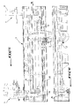
- FIG. 1 shows in schematic form the structural principle of a first embodiment of an automatic rail grinder
- this machine essentially comprises a grinding wheel 1 placed on a movable furniture trolley 2 along a beam 3 which is pivotally mounted at each of its ends on a device 4 for translational movement of the beam 3.
- This translational drive device 4 for the beam is mounted on a module 5 for rotation of the beam around the rail 6.
- the module 5 comprises a crown 7 on which the device 4 is mounted and which is capable of carrying out a rotary movement relative to a fixed crown element 8 by means of rolling means such as balls 9, as shown in FIG. 2, the crown 7 being fixedly mounted on a support frame 10 which comprises two elements 11 and 12 each in the form of a frame through which the rail 6 extends.
- the two elements ents of the frame are placed at a certain distance from each other, in the longitudinal direction of the rail 6.
- the grinding wheel 1 is rotatably mounted on the carriage 2 and is rotated by a hydraulic motor 15 carried by the carriage 2. Thanks to this type of motor, the space requirement is reduced, the structure is compact and the center of gravity approaches of the grinding wheel.
- the translational drive device 4 of the beam 3 comprises essentially a motor element 17 such as a jack provided with a rod 18 at the end of which the end of the beam 3 is articulated.
- the grinder further comprises a rail retaining device 6, which essentially comprises abutment members 19 as well as at each frame frame 12 and 13 a rail clamping cylinder 20 and a rail clamping cylinder 21, which act perpendicular to the longitudinal direction of the rail to push it on the stop elements 19, respectively in the lateral and vertical directions.
- the piston rod of the clamping cylinder 21 carries at its free end a pusher element 23 intended to come to bear on the external face of the head of the rail.
- This pusher element 23 carries a vibration sensor 24.
- the rotary rings 7 of the rotation modules 5 of the beam 3 are driven in rotation by a device which essentially comprises a motor member 26 whose rotary axis 27 carries, integral in rotation, drive members such as pinions 28 which mesh with a corresponding gear provided on the crown 7.
- a device which essentially comprises a motor member 26 whose rotary axis 27 carries, integral in rotation, drive members such as pinions 28 which mesh with a corresponding gear provided on the crown 7.
- a device which essentially comprises a motor member 26 whose rotary axis 27 carries, integral in rotation, drive members such as pinions 28 which mesh with a corresponding gear provided on the crown 7.
- FIG. 3a schematically shows the beam 3 in its starting position above the end-to-end junction zone by welding two rail elements R 1 , R 2 of the rail 6 of FIG. 1.
- the beam 3 is oriented substantially parallel to the rail, the carrier carriage 2 of the grinding wheel 1 is in its end position on the left side.
- FIG. 5b illustrates the taking of the reference point on the left side.
- the translation drive device 4 is actuated on the left side, which lowers the left end of the beam 3 until the grinding wheel 2 comes into contact with the surface of the rail element R 1 at point P 1 .
- the contact of the grinding wheel with the rail is detected by the vibration or sound sensor 24 which sends appropriate information to the programmable controller which stores the geometric coordinates of this contact point as reference coordinates on the left side.
- the PLC has been programmed accordingly. It comprises a computer device in the memory of which the geometrical information defining the relative geometrical position of the rail 6 relative to the beam and the grinding wheel has been previously entered in an appropriate reference system. After establishing the reference point on the left side, the reference point is established on the right side by bringing the carriage 2 to its right end position indicated in broken lines in FIG. 5b and by lowering the right end of the beam 3 using the translational drive device 4 associated with this end, until the grinding wheel 1 comes into contact with the right-hand rail element R 2 . The right reference point P 2 is thus defined.
- the automaton having recorded the difference in levels between the reference points P 1 and P 2 as well as the end position P 3 on the right side, it is able to automatically decompose the distance between points P 2 and P 3 in a certain number of passes, so as not to exceed a certain depth of pass, which ensures excellent regularity and security.
- the different phases of establishment of the reference and grinding points, which have just been described are those which the grinder performs when the beam 3 is in a predetermined angular position relative to the rail 6.
- the result of the work of the grinding wheel is a planar facet which extends parallel to the longitudinal direction of the rail, such as facet 31 in FIG. 4.
- the profile of the rail is broken down into a succession of facets, as shown in Figure 4.
- it is necessary to respect an angular difference between adjacent facets which depends on the radius of curvature of the fungus.
- the grinding is done by a succession of elementary processes described above.
- the grinding wheel After completion of a facet, the grinding wheel is moved away from the rail, the new angular position of the beam and the grinding wheel is determined and the steps described are repeated. Since at the beginning of each grinding of a facet, the reference system is again established, the wear of the grinding wheel occurs in a negligible manner during the whole process of grinding of the considered junction.
- FIG. 7 shows that the carriage 2 carrying the grinding wheel 1 is guided on the beam by means of the upper and lower slides 34, 35 which are arranged respectively above and below the jack 33. Thanks to these different structural characteristics, thrust axes, guidance, grinding and gravity are very close to each other and create a very good dynamic situation.
- FIG. 6 shows another advantageous feature of the grinder according to the invention which resides in the fact that the articulation pivot of the left end of the beam 3 to the corresponding vertical displacement device 4 has a retracted shape so that the carriage can move to an end position which ensures that the point of contact of the grinding wheel 1 with the rail 6 when establishing the reference point on the left side, that is to say P 1 , is located substantially vertically below the pivot axis.
- the beam is provided with a casing, the front and rear parts of which bear the references 36 and 37 respectively.
- FIGs 8 to 11 show another embodiment of an automatic rail grinder according to the invention.
- This grinder is designed to constitute a site grinder. To this end it is mounted on a chassis 40 which is movable on the railroad track comprising the rail 6 to be ground, using two flanged wheels bearing the reference 41 and 42 and a cylindrical roller 43.
- the chassis has a shape substantially triangular, a wheel being arranged at each angle.
- the wheels 41 and 42 are associated with the same rail 6, while the roller 43 moves on the other rail 6.
- the beam 3 which carries the wheel carriage 2 is mounted on the chassis 40 so as to extend parallel to the rail 6, with which the two wheels 41 and 42 are associated.
- the beam assembly 3 is mounted at each end on the chassis 40, pivoting around a pivot 45 housed in a bearing 46 fixed to the chassis, on the lower surface thereof, just next to the corresponding wheel 41, 42 in the longitudinal direction of the rail 6.
- a hydraulic clamping ring 44 is interposed between the pivot and the bearing.
- the pivot 45 extends parallel to this rail ( Figure 11).
- the pivot 45 is fixed to the end of an arm 47, the other end of which is integral with the beam.
- the site grinder is provided with an operating hoop 49 to ensure manual pivoting of the beam around the rail 6 to be ground.
- the rolling chassis 40 is of course equipped with means 50 allowing it to be locked in a predetermined position on the rails 6 on which there is a sound sensor.
- the references 52 designate the power and control unit of the grinder.
Landscapes
- Engineering & Computer Science (AREA)
- Mechanical Engineering (AREA)
- Architecture (AREA)
- Civil Engineering (AREA)
- Structural Engineering (AREA)
- Machines For Laying And Maintaining Railways (AREA)
- Grinding And Polishing Of Tertiary Curved Surfaces And Surfaces With Complex Shapes (AREA)
Claims (9)
- Verfahren zum Schleifen der Stumpfschweißverbindung zweier Elemente, wie Schienen gemäss welchem auf beiden Seiten der Verbindungszone ein Referenzpunkt bestimmt wird durch Herstellung eines Kontaktes zwischen Referenzgliedern mit der Schiene und wo die Elemente in der Verbindungszone während mindestens eines durch die so bestimmten Referenzpunkte definierten Arbeitsganges geschliffen werden, wo die Herstellung des Kontaktes zwischen dem Schleifkörper und der Schiene von einem Tonaufnehmer angegeben wird, dadurch gekennzeichnet, dass als Referenzglied der Schleifkörper (1) selbst verwendet wird und dieser zuerst mit der Schiene auf einer Seite der Verbindung und anschliessend auf der anderen in Kontakt gebracht wird und die Daten gespeichert werden, die diese Kontaktpunkte als Referenzwerte definieren.
- Verfahren nach Anspruch 1, dadurch gekennzeichnet, dass der Bereich des zu schleifenden Schienenkopfes in eine Mehrzahl von Schleifflächen (31) unterteilt wird, die im Querschnitt der Schiene (6) nebeneinander angeordnet sind und dass der besagte Bereich geschliffen wird, indem nacheinander die besagten Schleifflächen geschliffen werden.
- Verfahren nach Anspruch 2, dadurch gekennzeichnet, dass der Schleifkörper von der Schiene entfernt wird nach dem Schleifen jeder Schleiffläche und dass die Referenzpunkte für das Schleifen der nächsten Schleiffläche vor Beginn des Schleifens bestimmt werden.
- Schleifmaschine zur Durchführung des Verfahrens gemäss einem der vorhergehenden Ansprüche, von der Art mit von einem Scheibenschlitten getragenen Schleifkörper der axial längs eines Balkens bewegbar ist, wobei dieser an seinen Enden an einer eine Winkelbewegung um die Schiene ausführenden Vorrichtung schwenkbar angeordnet ist, dadurch gekennzeichnet, dass der Schleifkörper (1) das Herstellungsglied der Referenzpunkte für das Schleifen bildet und dass ein programmierbarer Automat vorgesehen ist, um von den Referenzpunkten ausgehend die Daten zu erstellen, die ein automatisches Schleifen des zu schleifenden Bereiches ermöglichen.
- Schleifmaschine gemäss Anspruch 4, dadurch gekennzeichnet, dass der Scheibenschlitten (2) einen hydraulischen Motor (15) trägt, um den Schleifkörper (1) in Drehbewegung zu versetzen.
- Schleifmaschine gemäss einem der Ansprüche 4 oder 5, dadurch gekennzeichnet, dass die Verschiebevorrichtung des Scheibenschlittens (2) längs des Balkens (3) von einem im Inneren des Balkens vorgesehenen stangenlosen Zylinder (32) gebildet wird.
- Schleifmaschine gemäss Anspruch 6, dadurch gekennzeichnet, dass der Scheibenschlitten (2) mittels Führungsschienen (35) längs des Balkens (3) bewegbar ist, die jeweils oberhalb und unterhalb des stangenlosen Zylinders (33) angeordnet sind.
- Schleifmaschine gemäss einem der Ansprüche 4 bis 7, dadurch gekennzeichnet, dass der Balken (3) auf einem Drehmodul (5) des Balkens um die Schiene (6) angebracht ist, wobei dieses Modul (5) ortsfest auf einem Traggestell (10) angeordnet ist.
- Schleifmaschine gemäss einem der Ansprüche 4 bis 7, dadurch gekennzeichnet, dass der Tragrahmen des Balkens (3) mittels Rädern (41 bis 43) auf den Schienen (6) bewegbar ist und in einer Schleifposition einer Schiene durch die Winkelbewegung des Balkens (3) um diese Schiene feststellbar ist.
Applications Claiming Priority (2)
| Application Number | Priority Date | Filing Date | Title |
|---|---|---|---|
| FR9212299 | 1992-10-14 | ||
| FR9212299A FR2696762B1 (fr) | 1992-10-14 | 1992-10-14 | Procédé de meulage de la jonction bout-à-bout par soudage notamment de deux rails et machine de meulage pour la mise en Óoeuvre de ce procédé. |
Publications (2)
| Publication Number | Publication Date |
|---|---|
| EP0593361A1 EP0593361A1 (de) | 1994-04-20 |
| EP0593361B1 true EP0593361B1 (de) | 1997-02-19 |
Family
ID=9434541
Family Applications (1)
| Application Number | Title | Priority Date | Filing Date |
|---|---|---|---|
| EP93402526A Expired - Lifetime EP0593361B1 (de) | 1992-10-14 | 1993-10-13 | Verfahren und Vorrichtung zum Schleifen zweier stumpf aneinanderstossender Schienen |
Country Status (4)
| Country | Link |
|---|---|
| EP (1) | EP0593361B1 (de) |
| AT (1) | ATE149049T1 (de) |
| DE (1) | DE69308185T2 (de) |
| FR (1) | FR2696762B1 (de) |
Cited By (1)
| Publication number | Priority date | Publication date | Assignee | Title |
|---|---|---|---|---|
| US7350467B2 (en) | 2004-08-20 | 2008-04-01 | Loram Maintenance Of Way, Inc. | Long rail pick-up and delivery system |
Families Citing this family (6)
| Publication number | Priority date | Publication date | Assignee | Title |
|---|---|---|---|---|
| DE20004932U1 (de) * | 2000-03-17 | 2001-07-26 | Partech Produktionsekonomi Ab, Skara | Vorrichtung zum Schleifen von Schienen |
| FR2814765B1 (fr) | 2000-09-29 | 2004-02-13 | Geismar Ancien Ets L | Systeme de commande de la meule d'une machine de meulage notamment de rails |
| RU2272091C2 (ru) * | 2002-01-30 | 2006-03-20 | Государственное унитарное предприятие Калужский завод "Ремпутьмаш" | Устройство для шлифовки стыков рельса |
| GB0401403D0 (en) * | 2004-01-22 | 2004-02-25 | Balfour Beatty Plc | Rail joint grinding |
| EA009583B1 (ru) * | 2005-07-05 | 2008-02-28 | Общество с ограниченной ответственностью "ВЕСТ-ТЕР" | Способ грубой шлифовки сварного стыка железнодорожных рельсов |
| DE202018004312U1 (de) * | 2018-09-17 | 2018-10-10 | Goldschmidt Thermit Gmbh | Vorrichtung zum Reprofilieren und Entgraten von Schienen |
Family Cites Families (4)
| Publication number | Priority date | Publication date | Assignee | Title |
|---|---|---|---|---|
| CH592780A5 (de) * | 1976-01-07 | 1977-11-15 | Speno International | |
| US4862647A (en) * | 1987-08-31 | 1989-09-05 | Loram Maintenance Of Way, Inc. | Rail grinding machine |
| ATE66030T1 (de) * | 1987-11-07 | 1991-08-15 | Scheuchzer Fils Auguste | Schleifmaschine fuer die reprofilierung von schienenkoepfen. |
| CH675440A5 (de) * | 1988-03-04 | 1990-09-28 | Speno International |
-
1992
- 1992-10-14 FR FR9212299A patent/FR2696762B1/fr not_active Expired - Fee Related
-
1993
- 1993-10-13 AT AT93402526T patent/ATE149049T1/de not_active IP Right Cessation
- 1993-10-13 EP EP93402526A patent/EP0593361B1/de not_active Expired - Lifetime
- 1993-10-13 DE DE69308185T patent/DE69308185T2/de not_active Expired - Fee Related
Cited By (2)
| Publication number | Priority date | Publication date | Assignee | Title |
|---|---|---|---|---|
| US7350467B2 (en) | 2004-08-20 | 2008-04-01 | Loram Maintenance Of Way, Inc. | Long rail pick-up and delivery system |
| US7895950B2 (en) | 2004-08-20 | 2011-03-01 | Loram Maintenance Of Way, Inc. | Long rail pick-up and delivery system |
Also Published As
| Publication number | Publication date |
|---|---|
| FR2696762B1 (fr) | 1994-12-30 |
| DE69308185D1 (de) | 1997-03-27 |
| ATE149049T1 (de) | 1997-03-15 |
| EP0593361A1 (de) | 1994-04-20 |
| FR2696762A1 (fr) | 1994-04-15 |
| DE69308185T2 (de) | 1997-09-11 |
Similar Documents
| Publication | Publication Date | Title |
|---|---|---|
| EP0044964B1 (de) | Schleifvorrichtung zum Profilieren einer Eisenbahnschiene | |
| EP1606079B1 (de) | Maschine zum schleifen von optischen linsen | |
| EP0235602B1 (de) | Verfahren zum Messen und Schleifen eines Schienenkopfprofils | |
| FR2585276A2 (fr) | Machine executant diverses operations d'usinage telles que tournage, fraisage, alesage | |
| EP0216695B1 (de) | Verfahren und Maschine zur Herstellung von Rotationshohlkörpern aus in drei verschiedenen Richtungen verlaufenden Gespinstfasern | |
| CA1268976A (fr) | Procede et installation d'usinage d'une piece creuse par fraisage le long d'un trace predetermine | |
| EP0593361B1 (de) | Verfahren und Vorrichtung zum Schleifen zweier stumpf aneinanderstossender Schienen | |
| FR2474076A1 (fr) | Procede d'elimination des defauts des champignons des rails d'une voie ferree posee et machine permettant son execution | |
| EP0501183B1 (de) | Vorrichtung zur Wiederprofilierung von Eisenbahnschienen | |
| FR2565857A1 (fr) | Machine pour la realisation de corps d'armature pour des tubes en beton | |
| CH678341A5 (de) | ||
| FR2695853A1 (fr) | Machine à fraiser, à surfacer et à polir à changement automatique d'outils et dispositif correspondant. | |
| EP0820837A1 (de) | Maschine zum Schleifen optischer Gläser | |
| EP2036727B1 (de) | Druckvorrichtung, Einstellungsverfahren und Druckverfahren | |
| FR2463228A1 (fr) | Machine mobile sur une voie ferree servant a eliminer les defauts de surface des rails | |
| WO1992002396A1 (fr) | Dispositif de positionnement a l'arret pour chariot de manutention | |
| FR2482891A1 (fr) | Machine interne electromecanique a meuler a une seule tete porte-ouvrage et comportant une broche de meulage directement sur le chariot transversal | |
| FR2528745A1 (fr) | Procede pour deplacer tridimensionnellement un outil et machine-outil pour sa mise en oeuvre | |
| FR2476059A1 (fr) | Machine et procede pour conformer le bord d'une plaque de verre | |
| FR2492284A1 (fr) | Laminoir pour tubes d'acier | |
| FR2725931A1 (fr) | Procede et dispositif pour couper une surface dans un bloc de matiere et machine comprenant un tel dispositif | |
| EP0789108A1 (de) | Rollwagen mit Schleif- oder Bearbeitungswerkzeuge für die Lauffläche und das Pilzteil von Eisenbahnschienen | |
| FR2600375A1 (fr) | Procede d'exploitation de carriere et de debitage direct de pierres ou autres et dispositif pour sa mise en oeuvre | |
| FR2826599A1 (fr) | Procede de percage de verres optiques, et dispositif de mise en oeuvre dudit procede | |
| FR2625458A1 (fr) | Cellule de meulage |
Legal Events
| Date | Code | Title | Description |
|---|---|---|---|
| PUAI | Public reference made under article 153(3) epc to a published international application that has entered the european phase |
Free format text: ORIGINAL CODE: 0009012 |
|
| AK | Designated contracting states |
Kind code of ref document: A1 Designated state(s): AT CH DE FR GB IT LI SE |
|
| 17P | Request for examination filed |
Effective date: 19941018 |
|
| GRAG | Despatch of communication of intention to grant |
Free format text: ORIGINAL CODE: EPIDOS AGRA |
|
| 17Q | First examination report despatched |
Effective date: 19960418 |
|
| GRAH | Despatch of communication of intention to grant a patent |
Free format text: ORIGINAL CODE: EPIDOS IGRA |
|
| GRAH | Despatch of communication of intention to grant a patent |
Free format text: ORIGINAL CODE: EPIDOS IGRA |
|
| GRAA | (expected) grant |
Free format text: ORIGINAL CODE: 0009210 |
|
| AK | Designated contracting states |
Kind code of ref document: B1 Designated state(s): AT CH DE FR GB IT LI SE |
|
| REF | Corresponds to: |
Ref document number: 149049 Country of ref document: AT Date of ref document: 19970315 Kind code of ref document: T |
|
| REG | Reference to a national code |
Ref country code: CH Ref legal event code: EP |
|
| REF | Corresponds to: |
Ref document number: 69308185 Country of ref document: DE Date of ref document: 19970327 |
|
| ITF | It: translation for a ep patent filed | ||
| GBT | Gb: translation of ep patent filed (gb section 77(6)(a)/1977) |
Effective date: 19970522 |
|
| REG | Reference to a national code |
Ref country code: CH Ref legal event code: NV Representative=s name: TROESCH SCHEIDEGGER WERNER AG |
|
| PLBE | No opposition filed within time limit |
Free format text: ORIGINAL CODE: 0009261 |
|
| STAA | Information on the status of an ep patent application or granted ep patent |
Free format text: STATUS: NO OPPOSITION FILED WITHIN TIME LIMIT |
|
| 26N | No opposition filed | ||
| REG | Reference to a national code |
Ref country code: GB Ref legal event code: IF02 |
|
| PGFP | Annual fee paid to national office [announced via postgrant information from national office to epo] |
Ref country code: GB Payment date: 20031008 Year of fee payment: 11 |
|
| PGFP | Annual fee paid to national office [announced via postgrant information from national office to epo] |
Ref country code: SE Payment date: 20041006 Year of fee payment: 12 |
|
| PG25 | Lapsed in a contracting state [announced via postgrant information from national office to epo] |
Ref country code: GB Free format text: LAPSE BECAUSE OF NON-PAYMENT OF DUE FEES Effective date: 20041013 |
|
| GBPC | Gb: european patent ceased through non-payment of renewal fee |
Effective date: 20041013 |
|
| PG25 | Lapsed in a contracting state [announced via postgrant information from national office to epo] |
Ref country code: IT Free format text: LAPSE BECAUSE OF NON-PAYMENT OF DUE FEES;WARNING: LAPSES OF ITALIAN PATENTS WITH EFFECTIVE DATE BEFORE 2007 MAY HAVE OCCURRED AT ANY TIME BEFORE 2007. THE CORRECT EFFECTIVE DATE MAY BE DIFFERENT FROM THE ONE RECORDED. Effective date: 20051013 |
|
| PG25 | Lapsed in a contracting state [announced via postgrant information from national office to epo] |
Ref country code: SE Free format text: LAPSE BECAUSE OF NON-PAYMENT OF DUE FEES Effective date: 20051014 |
|
| EUG | Se: european patent has lapsed | ||
| PGFP | Annual fee paid to national office [announced via postgrant information from national office to epo] |
Ref country code: DE Payment date: 20061005 Year of fee payment: 14 |
|
| PGFP | Annual fee paid to national office [announced via postgrant information from national office to epo] |
Ref country code: AT Payment date: 20061011 Year of fee payment: 14 |
|
| PG25 | Lapsed in a contracting state [announced via postgrant information from national office to epo] |
Ref country code: DE Free format text: LAPSE BECAUSE OF NON-PAYMENT OF DUE FEES Effective date: 20080501 |
|
| PG25 | Lapsed in a contracting state [announced via postgrant information from national office to epo] |
Ref country code: AT Free format text: LAPSE BECAUSE OF NON-PAYMENT OF DUE FEES Effective date: 20071013 |
|
| PGFP | Annual fee paid to national office [announced via postgrant information from national office to epo] |
Ref country code: CH Payment date: 20081031 Year of fee payment: 16 |
|
| PGFP | Annual fee paid to national office [announced via postgrant information from national office to epo] |
Ref country code: FR Payment date: 20081028 Year of fee payment: 16 |
|
| REG | Reference to a national code |
Ref country code: CH Ref legal event code: PL |
|
| REG | Reference to a national code |
Ref country code: FR Ref legal event code: ST Effective date: 20100630 |
|
| PG25 | Lapsed in a contracting state [announced via postgrant information from national office to epo] |
Ref country code: FR Free format text: LAPSE BECAUSE OF NON-PAYMENT OF DUE FEES Effective date: 20091102 |
|
| PG25 | Lapsed in a contracting state [announced via postgrant information from national office to epo] |
Ref country code: LI Free format text: LAPSE BECAUSE OF NON-PAYMENT OF DUE FEES Effective date: 20091031 Ref country code: CH Free format text: LAPSE BECAUSE OF NON-PAYMENT OF DUE FEES Effective date: 20091031 |