EP0593391B1 - Appareil pour changer le paquet d'enroulement - Google Patents
Appareil pour changer le paquet d'enroulement Download PDFInfo
- Publication number
- EP0593391B1 EP0593391B1 EP93810661A EP93810661A EP0593391B1 EP 0593391 B1 EP0593391 B1 EP 0593391B1 EP 93810661 A EP93810661 A EP 93810661A EP 93810661 A EP93810661 A EP 93810661A EP 0593391 B1 EP0593391 B1 EP 0593391B1
- Authority
- EP
- European Patent Office
- Prior art keywords
- swivelling
- lap
- reserve
- working position
- receiving means
- Prior art date
- Legal status (The legal status is an assumption and is not a legal conclusion. Google has not performed a legal analysis and makes no representation as to the accuracy of the status listed.)
- Expired - Lifetime
Links
Images

Classifications
-
- D—TEXTILES; PAPER
- D01—NATURAL OR MAN-MADE THREADS OR FIBRES; SPINNING
- D01G—PRELIMINARY TREATMENT OF FIBRES, e.g. FOR SPINNING
- D01G27/00—Lap- or sliver-winding devices, e.g. for products of cotton scutchers, jute cards, or worsted gill boxes
- D01G27/04—Lap- or sliver-winding devices, e.g. for products of cotton scutchers, jute cards, or worsted gill boxes with automatic discharge of lap-roll or the like
-
- D—TEXTILES; PAPER
- D01—NATURAL OR MAN-MADE THREADS OR FIBRES; SPINNING
- D01G—PRELIMINARY TREATMENT OF FIBRES, e.g. FOR SPINNING
- D01G19/00—Combing machines
- D01G19/06—Details
- D01G19/08—Feeding apparatus
Definitions
- the invention relates to a device and a method for receiving and tracking a reserve winder on a machine processing cotton wadding, the reserve winder being held in readiness on a receptacle at a radial distance from the wadding wrap in the working position and after removal of the empty sleeve of the wadding wrap on a machine Guide below the reserve winding, in the working position is transferred.
- a generic device is known from JP-B-63-27449, a reserve winding behind the working winding being kept on standby on a sloping rolling surface.
- a pivotable plate is arranged in the area of the rolling surface, which can be moved from the locked position into a release position via an adjustment mechanism.
- Below this rolling surface there is a pivotable receptacle for the empty sleeve ejected to the rear via an ejection device. This pivotable receptacle is connected to the adjustment mechanism for unlocking the pivotable plate.
- JP-U-52-64823 shows a more compact design, the reserve winding being mounted in a position close to the work winding.
- the reserve reel is also held in its reserve position by means of a pivotable plate and is arranged higher than the work reel. Due to this higher placement of the reserve position, it is possible to dispense the expired sleeve directly below the pivotable locking plate to the rear.
- a disadvantage of this embodiment is the tracking of the reserve winding from a relatively high position into the working position via a guide surface. This means that during the unwinding process, the mass of the reserve winding is greatly accelerated and has to be braked to prevent it from rolling over the working position. This process can either be carried out manually or with the appropriate braking elements.
- the invention is therefore based on the object of proposing a device and a method for receiving and tracking a reserve winding, which on the one hand enables a compact design and gentle winding transfer and on the other hand is problem-free and automatic delivery of the empty tubes backwards.
- the characterizing part of the device according to claim 1 wherein the device consists of a pivotally mounted receptacle having two pivot elements arranged at a horizontal distance from one another, at least a portion of the clear horizontal distance of the pivot elements being greater than the length of the sleeve of the wrap is.
- the receptacle is designed as a trough.
- this enables a safe position to be maintained in the reserve position of the wedge and, on the other hand, a gentle transfer to the working position.
- the trough can be designed in such a way that only a short taxi path has to be covered during the swiveling process in the direction of the working position. This avoids increased acceleration of the wadding during the transfer process and ensures a gentle transfer.
- the swivel elements are advantageously designed as swivel arms.
- the swivel elements are advantageously designed as a multi-unit gear, for example as a four-bar linkage, an exact adaptation to a smooth transfer process is achieved.
- the pivoting movement of the pivoting elements can take place via a cylinder articulated on the pivoting element.
- pneumatic cylinders can be used, via which a smooth transfer process can be carried out.
- damping element for example a throttle in the pneumatic circuit.
- An appropriately attached compression or tension spring can also be used as the damping element.
- this is transferred to a recording below the reserve position.
- This transfer can be supported by attaching a sloping guide surface that is connected to the working position.
- the object of the invention is also achieved by the characterizing part of the method according to claim 19, in particular the automatic removal of the sleeve, the automatic transfer of the reserve winding, and the controlled pivoting back of the reserve winding receptacle into the ready position after removal of the empty sleeve, is claimed.
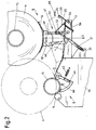
- FIG. 1 shows a schematic side view of a combing head 2, a combing machine 1 with a winding take-up position 3, also called a working position, in which a working winding 4 (cotton winding) shown in dashed lines rests on winding rollers 5 and 6. At least one of the winding rollers 5, 6 is provided with a drive 82 and thus ensures that the work roll 4 is unwound.
- the dash-dotted and unwound wadding web 7 is transferred to a pair of pliers, not shown, which presents the wadding to a round comb, also not shown, for combing out.
- Such a device can be found, for example, in EP-A-437807.
- combing heads 2 are arranged next to one another on a combing machine 1.
- the exemplary embodiment is described using a combing head.
- a reserve position 8 with a reserve winding 9 is provided for the working position 3, which is in a waiting position and is received in a trough 10.
- the trough 10 can also extend over the length of, for example, four combing heads 2, in which case a total of four reserve windings 9 can be accommodated in the trough 10 at the same time.
- the trough 10 is pivotally mounted about a pivot axis 12 via pivot arms 11.
- the pivot axis 12 is fastened in a support 13 which is attached to the frame 14 of the combing machine 1.
- Two swivel arms 11 arranged at a distance from one another are attached to the trough 10 in the region of a reserve winding 9.
- the distance A between the two swivel arms 11 is selected so that the passage of an empty sleeve 15 with the width B between the swivel arms 11 is ensured.
- a bolt 18, on which a cylinder 19 engages, is fastened to at least one swivel arm 11.
- the cylinder 19 is pivotally attached to the frame 14 at its opposite end on an axis of rotation 20.
- a stop 21 is attached, which interacts with a locking element 22, which is pivotably mounted on the frame 14 about the pivot axis 23.
- the locking element 22, referred to for short as a bolt is pivotably mounted on a cylinder 24 articulated on the support 13.
- a guide plate 25 is also fastened to the support 13, which is guided up to the winding roller 6 and forms a rolling surface sloping towards the rear for an empty sleeve 15.
- the guide plate 25 is angled and provided with a stop 26, which serves as a damping element for braking the sleeve 15 rolling backwards and can be made, for example, of a rubber or foam material.
- the rear part of the guide plate 25 forms a type of receiving trough 27 for the sleeve 15 ejected to the rear.
- FIG. 1 there is an empty and expired sleeve 15 on the winding rollers 5, 6, which can be transferred to the guide plate 25 to the rear by means of two gripping arms 31 pivotably spaced apart on an axis of rotation 30.
- the respective gripper arm 31, which is arranged pivotably in the region of the end face of the sleeve 15, is in each case provided with a latch 32 which can be pivoted in the direction of the inside diameter D of the sleeve 15 and which in cooperation with a conical bolt 33, which is likewise on the gripper arm 31 is attached, the transfer of the sleeve 15 makes.
- the bolt 33 could also be designed as a rotatably mounted roller, which performs an additional function for pressing the sleeve 15 onto the winding rollers 5, 6 via its outer peripheral surface.
- the pressing of the sleeve 15 is required in accordance with the example according to EP-A1 455171 to tear off or prepare the outgoing wadding web for a new application process of a new roll.
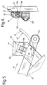
- FIG. 5 An enlarged representation of this partial area of the gripping arm 31 can be seen from FIG. 5 or FIG. 6.
- the bolt 32 is pivotally mounted on a pivot axis 34 of a bearing part 35 attached to the gripper arm 31.
- a spring 36 articulated on the bearing part 35 and on one leg 37 of the bolt 32 causes a pivoting movement of the bolt 32 in a clockwise direction.
- the bolt 32 can pivot until its leg 37 rests on a stop 38 of the bearing part 35.
- the bolt 32 is in a disengaged position, in which it is held by a stop 41 attached to the frame 14.
- the engagement position of the bolt 32 for the sleeve 15 is shown in phantom.
- the sleeve 15 Shortly before delivery to the guide plate 25, the sleeve 15, as indicated by dash-dotted lines in FIG. 5, lies on the bolt 33 due to the force of gravity. When the gripping arms 31 are pivoted further down, the sleeve 15 comes to rest on the guide plate 25 and can roll backwards into the receiving trough 27 as a result of the disengaged position of the latch 32.
- the pivoting movement of the gripping arms takes place via a schematically indicated drive 43.
- This drive 43 can consist, for example, of a motor which is connected to the axis of rotation 30 via gear elements.
- Another solution for pivoting the gripping arms 31 could be provided in that additional pivoting elements are attached to the axis of rotation 30 which can be pivoted by a cylinder.
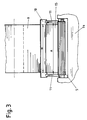
- a sleeve ejector 44 according to the exemplary embodiment according to FIG. 2 can also be used to eject the sleeves 15 to the rear.
- the ejector 44 is rotatably mounted about the winding roller 6 and is pivoted out of its position via a cylinder 45.
- the cylinder 45 is pivotally articulated on the one hand on the frame 14 and on the other hand on the ejector 44.
- the exemplary embodiment according to FIG. 2 differs from the exemplary embodiment according to FIG. 1 in the use of a four-bar linkage 47 for pivoting the trough 10 instead of the pivot arms 11.
- the four-bar linkage 47 consists of two handlebars 48 and 49 of unequal length, each of which is pivotally mounted at one end to the support 13 and the other end to a plate 50 fastened to the trough 10.
- a cylinder 51 engages the handlebars 48 in a pivot axis 52, while its other end is pivotally articulated on the pivot axis 20 on the frame 14.
- a stop 53 is additionally attached, which is overlapped by a bolt 55 which can be pivoted about the axis of rotation 54.
- the bolt 55 can be pivoted via a cylinder 56 which is pivotably attached to the support 13.
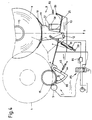
- the exemplary embodiment according to FIG. 4 shows a device similar to the example according to FIG. 1.
- the only difference here is the sleeve ejection device 44 already described for the execution of FIG. 2 and the changed articulation of the swivel arms 11 in the reserve position 8 with respect to the position of the center of gravity line S. That is, the center of gravity line S runs behind the swivel axis 12 with respect to the Working position 3. This creates a swing moment to the rear. This is received by a stop 57 on which a stop surface 58 of the swivel arm 11 comes to rest. This arrangement eliminates the need for special locking elements without endangering the stable and secure reserve position 8.
- a "sleeve empty" signal is emitted to a control unit 81 via a sensor 80 assigned to the working position.
- the control unit 81 stops the drive of the combing machine (not shown) and the drive 82 of the winding roller 5.
- the drive 43 of the gripper arms 31 is then set in motion via the control unit 81, the latch 32 on the peripheral surface of the sleeve 15 hits.
- the bolts 32 which are located on the left and right of the sleeve end face, are pivoted into the bearing part 35 against further pivoting against the spring force of the springs 36. As soon as the free leg of the bolt 32 reaches the inside diameter D of the sleeve 15, it is transferred by the spring into the locking position shown in broken lines in FIG.
- the sleeve wall is now between the circumferential surface of the bolt 33 and the bolt 32.
- the direction of rotation of the drive 43 is now reversed, whereby the sleeve 15 is pivoted backwards from the working position 3 in the direction of the guide plate 25.
- the bolt 32 Shortly before the sleeve 15 strikes with its outer circumference on the guide surface 25, the bolt 32 reaches the area of the bevel 42 of the stop 41 and is pivoted inward into the bearing part 35 upon further pivoting.
- the outer circumference of the sleeve 15 lies on the outer circumference of the respective bolts 33 (indicated by dash-dotted lines in FIG. 5).
- the sleeve comes to rest on the guide plate 25 and rolls below the trough 10 between the swivel arms 11 into the rear receiving trough 27. The rolling process is dampened by the attached stop 26.
- a sensor 83 which emits a signal to the central control unit 81. This triggers the actual transfer process of the reserve winding 9 into the working position 3.
- a transport unit can be positioned above the receiving trough 27, which Using appropriate gripping elements (not shown), the empty sleeves 15 are removed from the receiving trough 27 and disposed of. As soon as this process has been completed, which in turn is monitored by the sensor 83, the receiving trough 10 is transferred to the reserve position 8 via the cylinder 19. The latch 22 is brought into the locking position shown via the cylinder 24, whereby the reserve position is mechanically locked.
- the transfer process of the reserve roll 9 of the embodiment according to FIG. 2 or FIG. 4 essentially corresponds to the exemplary embodiment according to FIG. 1.
- an ejection device 44 is attached below the winding rollers 5, 6 for ejecting the empty sleeves 15, via which the sleeve 15 is moved back into the region of the guide surface 25 by actuating the cylinder 45.
- the latch 55 is designed as a type of pawl which, in the reserve position, lies over a stop 53.
Landscapes
- Engineering & Computer Science (AREA)
- Textile Engineering (AREA)
- Replacement Of Web Rolls (AREA)
- Preliminary Treatment Of Fibers (AREA)
Claims (19)
- Dispositif servant à réceptionner et à guider successivement un rouleau de réserve (9) dans une machine (1) traitant des rouleaux de nappe, et où le rouleau de réserve est maintenu en attente sur un logement, à une distance radiale par rapport au rouleau de nappe (4) se trouvant dans la position de travail (3), et est convoyé dans la position de travail (3) sur un guide (25) situé sous le rouleau de réserve, après éloignement du bobinot (15) du rouleau de nappe écoulé,
caractérisé par le fait que
le dispositif est constitué par un logement maintenu de façon à pouvoir réaliser un mouvement de pivotement et possédant deux éléments de pivotement (11,59,60,47) installés à distance horizontale l'un par rapport à l'autre, et où au moins une zone partielle de la distance horizontale (A) de l'écartement entre les éléments de pivotement est plus grande que la longueur du bobinot (B) du rouleau (9,4). - Dispositif selon revendication 1,
caractérisé par le fait que
le logement est formé comme une auge (10). - Dispositif selon une des revendications 1 à 2,
caractérisé par le fait que
les éléments de pivotement sont formés comme des bras de pivotement (11). - Dispositif selon une des revendications 1 à 2,
caractérisé par le fait que
les éléments de pivotement sont formés comme un mécanisme à plusieurs membres (47). - Dispositif selon revendication 4,
caractérisé par le fait que
le mécanisme à plusieurs membres est formé comme un quadrilatère articulé (47). - Dispositif selon une des revendications 1 à 5,
caractérisé par le fait que
le mouvement de pivotement des éléments de pivotement (11,59, 60,47) est effectué à l'aide d'un zylindre (19,69) fixé d'une manière articulée sur au moins un élément de pivotement. - Dispositif selon revendication 6,
caractérisé par le fait
qu'au moins un membre de blocage mécanique (22,55) est attribué au zylindre (19). - Dispositif selon une des revendications 1 à 7,
caractérisé par le fait que
l'élément de pivotement respectivement l'auge (10) peut être verrouillé dans une position de réserve postérieure (8), à l'aide du membre de blocage mécanique (22,55). - Dispositif selon revendication 8,
caractérisé par le fait que,
par rapport au centre de gravité (S) du rouleau de réserve (9) se trouvant en position de réserve, l'élément de pivotement est articulé de telle manière qu'il en résulte un moment de pivotement dans la direction de la position de travail (3). - Dispositif selon revendication 9,
caractérisé par le fait que
le ou les cylindres (19) et le verrouillage (22,55) sont disposés de telle façon que leur direction d'action est orientée à l'opposé de ce moment de pivotement. - Dispositif selon revendication 10,
caractérisé par le fait que
le mouvement de pivotement dans la direction de la position de travail (3) est atténué à l'aide d'un élément d'amortissement (86). - Dispositif selon revendication 6,
caractérisé par le fait que,
par rapport au centre de gravité (S) du rouleau de réserve (9) se trouvant en position de réserve, l'élément de pivotement est articulé de telle manière qu'il en résulte un moment de pivotement dans la direction opposée à la position de travail (3), et qu'une butée (57,79) est disposée d'une manière fixe dans la zone de pivotement de l'élément de pivotement (11,59,60) ou de l'auge (10), et maintient l'élément de pivotement dans une position de réserve fixe (8). - Dispositif selon une des revendications 1 à 12,
caractérisé par le fait que,
pour les bobinots (15), un arrangement d'éjection (31,44) est attribué à la position de travail (3). - Dispositif selon revendication 13,
caractérisé par le fait que,
sous la position de réserve (8) de l'auge (10), un logement (27) est prévu pour le bobinot vide éjecté (15). - Dispositif selon revendication 14,
caractérisé par le fait que
le logement (27) est en liaison avec la position de travail (3), via une surface de guidage inclinée (25). - Dispositif selon une des revendications 13 à 15,
caractérisé par le fait que
l'arrangement d'éjection est constitué par des bras (31) maintenus de façon à pouvoir réaliser un mouvement de pivotement, lesquels sont pourvus d'éléments de préhension mobiles (32). - Dispositif selon revendication 16,
caractérisé par le fait que,
dans la zone de pivotement des bras (31), des butées (41) sont disposées pour réaliser un convoyage des éléments de préhension (32) dans une position de relâchement pour les bobinots (15). - Dispositif selon une des revendications 1-17,
caractérisé par le fait que
la distance comprise entre la position de travail (3) et la position de réserve (8) est choisie de telle manière que, lors de la mise en place d'un rouleau de travail plein (4) et d'un rouleau de réserve (9), les cercles circonférentiels de ceux-ci s'entrecouperaient. - Procédé utilisé pour le guidage successif d'un rouleau de réserve (9) dans une machine traitant des rouleaux de nappe, et où le rouleau de réserve est maintenu en attente sur un logement, à une distance radiale par rapport au rouleau de nappe (4) se trouvant dans la position de travail, et est convoyé dans la position de travail sur un guide (25) situé sous le rouleau de réserve, après éloignement du bobinot (15) du rouleau de nappe écoulé,
caractérisé par les étapes de procédé suivantes:• Eloignement automatique du bobinot vide, hors de la position de travail, dans la direction du rouleau de réserve• Convoyage du bobinot (15) dans une réception de bobinots (27), située sous le logement qui porte le rouleau de réserve, et entre les éléments de pivotement (11,59,60,47) mettant en pivotement le logement (10)• Convoyage automatique du rouleau de réserve dans la position de travail, par pivotement du logement dans la direction de la position de travail• Eloignement du bobinot vide (15) via un système de transport• Pivotement en retour commandé du logement de rouleau de réserve (10), depuis la position de transfert dans la position en attente, pour la réception d'un nouveau rouleau de réserve.
Applications Claiming Priority (2)
| Application Number | Priority Date | Filing Date | Title |
|---|---|---|---|
| CH322992A CH685945A5 (de) | 1992-10-16 | 1992-10-16 | Vorrichtung zum Wickelwechsel. |
| CH3229/92 | 1992-10-16 |
Publications (2)
| Publication Number | Publication Date |
|---|---|
| EP0593391A1 EP0593391A1 (fr) | 1994-04-20 |
| EP0593391B1 true EP0593391B1 (fr) | 1997-01-08 |
Family
ID=4251438
Family Applications (1)
| Application Number | Title | Priority Date | Filing Date |
|---|---|---|---|
| EP93810661A Expired - Lifetime EP0593391B1 (fr) | 1992-10-16 | 1993-09-20 | Appareil pour changer le paquet d'enroulement |
Country Status (6)
| Country | Link |
|---|---|
| US (1) | US6059221A (fr) |
| EP (1) | EP0593391B1 (fr) |
| JP (1) | JP3537469B2 (fr) |
| CN (1) | CN1088537A (fr) |
| CH (1) | CH685945A5 (fr) |
| DE (1) | DE59305051D1 (fr) |
Cited By (2)
| Publication number | Priority date | Publication date | Assignee | Title |
|---|---|---|---|---|
| DE102006024555A1 (de) * | 2006-05-23 | 2007-12-06 | Saurer Gmbh & Co. Kg | Kämmmaschine mit Reservewinkelmulde |
| DE102017111357A1 (de) | 2017-05-24 | 2018-11-29 | TRüTZSCHLER GMBH & CO. KG | Pneumatikschaltung für einen Vlieswickler |
Families Citing this family (18)
| Publication number | Priority date | Publication date | Assignee | Title |
|---|---|---|---|---|
| DE19519144C2 (de) * | 1995-05-30 | 1998-06-18 | Csm Gmbh | Verfahren und Vorrichtung zum Transportieren von auf Vorbereitungsmaschinen hergestellten Wickeln |
| EP0770716A1 (fr) | 1995-10-23 | 1997-05-02 | Maschinenfabrik Rieter Ag | Fabrication d'une mèche peignée |
| DE19846915A1 (de) * | 1998-10-12 | 2000-04-13 | Rieter Ag Maschf | Zwischenspeicher für Wickel und Hülsen |
| DE10037143A1 (de) | 2000-07-31 | 2002-02-14 | Rieter Ag Maschf | Nachführung eines Reservewickels an einer Kämmaschine |
| DE10253340B4 (de) * | 2002-04-26 | 2007-02-15 | Volkmann Gmbh | Betätigungsventil für einen zweiseitig wirksamen Pneumatikzylinder sowie Verwendung eines solchen Betätigungsventils für mittels Pneumatikzylindern ansteuerbare Spulengatter |
| DE10253341A1 (de) * | 2002-04-26 | 2003-11-13 | Volkmann Gmbh | Spulengatter für Textilmaschinen sowie Betätigungsventil zum Verstellen eines solchen Spulengatters |
| EP1961685B1 (fr) * | 2007-02-23 | 2011-09-07 | Maschinenfabrik Rieter Ag | Dispositif de transmission d'un rouleau de nappe à un véhicule de transport |
| CN102205382B (zh) * | 2010-12-31 | 2013-01-23 | 凡登(常州)新型金属材料技术有限公司 | 超细钢丝连续生产线不间断放线自动切换装置 |
| EP2511209B1 (fr) * | 2011-04-11 | 2017-05-31 | Valmet Technologies, Inc. | Agencement pour la manipulation de rouleaux de machines et arbres d'enroulement relatifs à la production de réseaux de fibres |
| CN102583080A (zh) * | 2011-12-27 | 2012-07-18 | 济南泉华包装制品有限公司 | 一种改进的挤出机收卷架 |
| JP2014125307A (ja) * | 2012-12-26 | 2014-07-07 | Toyota Industries Corp | ラップ搬送台車 |
| JP5962518B2 (ja) * | 2013-01-09 | 2016-08-03 | 株式会社豊田自動織機 | コーマにおけるボビン排出及びラップ受入装置 |
| CN103407817A (zh) * | 2013-08-12 | 2013-11-27 | 苏州市盛百威包装设备有限公司 | 一种用于包装机的送膜机构 |
| CN104153056B (zh) * | 2014-07-31 | 2016-06-15 | 浙江新棉纺织有限公司 | 自动下料成卷机 |
| CN104153055B (zh) * | 2014-07-31 | 2016-06-01 | 浙江新棉纺织有限公司 | 成卷机换卷装置 |
| CN104528432A (zh) * | 2014-12-24 | 2015-04-22 | 江门市蓬江区华龙包装材料有限公司 | 一种卸膜卷装置 |
| KR102474885B1 (ko) * | 2015-11-10 | 2022-12-06 | 삼성에스디아이 주식회사 | 이차 전지용 권취 설비의 자재 교환 장치 |
| CN108557536A (zh) * | 2018-04-28 | 2018-09-21 | 重庆瑞霆塑胶有限公司 | 用于薄膜的收卷装置 |
Family Cites Families (16)
| Publication number | Priority date | Publication date | Assignee | Title |
|---|---|---|---|---|
| DE853571C (de) * | 1942-02-14 | 1952-10-27 | Alsacienne Constr Meca | Vorrichtung zum Auflegen von Speisewickeln auf Flachkaemmaschinen |
| GB825734A (en) * | 1957-01-23 | 1959-12-23 | Samuel M Langston Co | Apparatus for supporting web reels during unwinding |
| GB953405A (en) * | 1961-11-13 | 1964-03-25 | Tmm Research Ltd | Improved creeling arrangement for textile machines |
| JPS563932B2 (fr) * | 1973-07-20 | 1981-01-28 | ||
| GB1507827A (en) * | 1974-05-06 | 1978-04-19 | Canada Steel Co | Handling rolled transfer bars |
| JPS5264823A (en) * | 1975-11-25 | 1977-05-28 | Hitachi Denshi Ltd | Channel switching circuit |
| SE442626B (sv) * | 1979-08-16 | 1986-01-20 | Treom I Falkenberg Ab | Apparat for avrullning av en materialbana |
| JPS5943386A (ja) * | 1982-09-03 | 1984-03-10 | 株式会社東芝 | 原子炉建屋の建設方法 |
| IL82503A0 (en) * | 1986-05-16 | 1987-11-30 | Dow Chemical Co | Process for the promination of biphenols |
| IT1225957B (it) * | 1988-07-05 | 1990-12-10 | Cerit Spa | Processo di alimentazione automatica per pettinatrici |
| JP2645423B2 (ja) * | 1988-07-18 | 1997-08-25 | 株式会社原織機製作所 | 小玉ラップボビンを自動切断除去する方法と装置 |
| DE3836242A1 (de) * | 1988-10-25 | 1990-04-26 | Zinser Textilmaschinen Gmbh | Transporteinrichtung zum versorgen von mehreren kaemmaschinen mit wickeln |
| CH679591A5 (fr) * | 1989-08-23 | 1992-03-13 | Rieter Ag Maschf | |
| CH680670A5 (fr) * | 1990-01-17 | 1992-10-15 | Rieter Ag Maschf | |
| JP2763968B2 (ja) * | 1990-05-02 | 1998-06-11 | マシーネンフアブリーク リーテル アクチエンゲゼルシヤフト | ラップ処理機械におけるラップの接合方法及びラップ処理機械 |
| JP6327449B2 (ja) | 2014-03-28 | 2018-05-23 | 株式会社ワコール | カップ部を有する衣類 |
-
1992
- 1992-10-16 CH CH322992A patent/CH685945A5/de not_active IP Right Cessation
-
1993
- 1993-09-20 DE DE59305051T patent/DE59305051D1/de not_active Expired - Lifetime
- 1993-09-20 EP EP93810661A patent/EP0593391B1/fr not_active Expired - Lifetime
- 1993-10-15 CN CN93118920A patent/CN1088537A/zh active Pending
- 1993-10-15 JP JP25816093A patent/JP3537469B2/ja not_active Expired - Fee Related
-
1996
- 1996-03-05 US US08/611,416 patent/US6059221A/en not_active Expired - Fee Related
Cited By (3)
| Publication number | Priority date | Publication date | Assignee | Title |
|---|---|---|---|---|
| DE102006024555A1 (de) * | 2006-05-23 | 2007-12-06 | Saurer Gmbh & Co. Kg | Kämmmaschine mit Reservewinkelmulde |
| DE102006024555B4 (de) * | 2006-05-23 | 2012-04-05 | Oerlikon Textile Gmbh & Co. Kg | Kämmmaschine mit Reservewickelmulde |
| DE102017111357A1 (de) | 2017-05-24 | 2018-11-29 | TRüTZSCHLER GMBH & CO. KG | Pneumatikschaltung für einen Vlieswickler |
Also Published As
| Publication number | Publication date |
|---|---|
| CH685945A5 (de) | 1995-11-15 |
| JPH06207329A (ja) | 1994-07-26 |
| CN1088537A (zh) | 1994-06-29 |
| EP0593391A1 (fr) | 1994-04-20 |
| US6059221A (en) | 2000-05-09 |
| JP3537469B2 (ja) | 2004-06-14 |
| DE59305051D1 (de) | 1997-02-20 |
Similar Documents
| Publication | Publication Date | Title |
|---|---|---|
| EP0593391B1 (fr) | Appareil pour changer le paquet d'enroulement | |
| EP0933206B1 (fr) | Procédé et dispositifs pour amener et/ou enlever automatiquement des plaques d'impression vers le/du cylindre porte-plaque d'une machine à imprimer | |
| EP0414012B1 (fr) | Appareil de transport des enroulements de nappe | |
| EP0734859B1 (fr) | Dispositif pour changer des plaques d'impression | |
| DE3225379C2 (fr) | ||
| DE2847556A1 (de) | Revolverkopf-aufwickelmaschine fuer bandfoermiges material | |
| DE2150331A1 (de) | Verfahren und Vorrichtung zur Reinigung von Spinnkammern | |
| DE3123494C2 (de) | Verfahren und Vorrichtung zum Aufwinden eines neu angesponnenen Fadens auf eine in eine Spulvorrichtung eingelegte Leerhülse | |
| CH692111A5 (de) | Kreuzspulenwechseleinrichtung einer Kreuzspulen herstellenden Textilmaschine. | |
| DE3325999A1 (de) | Spinnmaschine mit einem spulenabnehmer | |
| DE4443818A1 (de) | Kreuzspulen herstellende Textilmaschine | |
| DD299664A5 (de) | Betriebsverfahren und vorrichtung zum automatisierten auswechseln von auflaufspulen, insbesondere zwirnkreuzspulen, gegen leere aufwickelhuelsen | |
| EP1231174B1 (fr) | Dispositif de sortie d'une machine à traiter des feuilles | |
| EP1961685B1 (fr) | Dispositif de transmission d'un rouleau de nappe à un véhicule de transport | |
| CH695692A5 (de) | Wickelvorrichtung zur Herstellung eines Wattewickels. | |
| DE3729776C2 (de) | Verfahren und Vorrichtung zum Entnehmen von Kreuzspulen aus dem Spulenrahmen und zum Ablegen auf eine Kreuzspulenempfangsvorrichtung | |
| DE2503545A1 (de) | Verfahren und vorrichtung zum spulenwechseln an textilmaschinen, insbesondere an offen-end-spinnmaschinen | |
| DE3216749A1 (de) | Umwindegarn-spinnaggregat | |
| DE3832249C2 (fr) | ||
| EP0838423B1 (fr) | Dispositif pour transférer un fil en défilement vers un dispositif d'aspiration à une bobine vide en rotation | |
| DE19910764A1 (de) | Verfahren und Vorrichtung zur Handhabung einer Leerhülse auf einer Textilmaschine | |
| DE1777272B2 (de) | Einrichtungen zum fuehren und greifen des ziehgutanfangs an einer ziehmaschine | |
| DE1685561C3 (de) | Vorrichtung an Strecken und Vorspinnmaschinen zum Wechseln der Aufwickelspulen | |
| CH680068A5 (fr) | ||
| EP0929705A1 (fr) | Dispositif d'enroulement |
Legal Events
| Date | Code | Title | Description |
|---|---|---|---|
| PUAI | Public reference made under article 153(3) epc to a published international application that has entered the european phase |
Free format text: ORIGINAL CODE: 0009012 |
|
| 17P | Request for examination filed |
Effective date: 19940202 |
|
| AK | Designated contracting states |
Kind code of ref document: A1 Designated state(s): CH DE IT LI |
|
| 17Q | First examination report despatched |
Effective date: 19950306 |
|
| GRAG | Despatch of communication of intention to grant |
Free format text: ORIGINAL CODE: EPIDOS AGRA |
|
| GRAH | Despatch of communication of intention to grant a patent |
Free format text: ORIGINAL CODE: EPIDOS IGRA |
|
| GRAH | Despatch of communication of intention to grant a patent |
Free format text: ORIGINAL CODE: EPIDOS IGRA |
|
| GRAA | (expected) grant |
Free format text: ORIGINAL CODE: 0009210 |
|
| AK | Designated contracting states |
Kind code of ref document: B1 Designated state(s): CH DE IT LI |
|
| REG | Reference to a national code |
Ref country code: CH Ref legal event code: EP |
|
| REF | Corresponds to: |
Ref document number: 59305051 Country of ref document: DE Date of ref document: 19970220 |
|
| ITF | It: translation for a ep patent filed | ||
| PLBE | No opposition filed within time limit |
Free format text: ORIGINAL CODE: 0009261 |
|
| STAA | Information on the status of an ep patent application or granted ep patent |
Free format text: STATUS: NO OPPOSITION FILED WITHIN TIME LIMIT |
|
| 26N | No opposition filed | ||
| PGFP | Annual fee paid to national office [announced via postgrant information from national office to epo] |
Ref country code: CH Payment date: 19980907 Year of fee payment: 6 |
|
| PG25 | Lapsed in a contracting state [announced via postgrant information from national office to epo] |
Ref country code: LI Free format text: LAPSE BECAUSE OF NON-PAYMENT OF DUE FEES Effective date: 19990930 Ref country code: CH Free format text: LAPSE BECAUSE OF NON-PAYMENT OF DUE FEES Effective date: 19990930 |
|
| REG | Reference to a national code |
Ref country code: CH Ref legal event code: PL |
|
| PGFP | Annual fee paid to national office [announced via postgrant information from national office to epo] |
Ref country code: DE Payment date: 20120921 Year of fee payment: 20 |
|
| PGFP | Annual fee paid to national office [announced via postgrant information from national office to epo] |
Ref country code: IT Payment date: 20120926 Year of fee payment: 20 |
|
| REG | Reference to a national code |
Ref country code: DE Ref legal event code: R071 Ref document number: 59305051 Country of ref document: DE |
|
| PG25 | Lapsed in a contracting state [announced via postgrant information from national office to epo] |
Ref country code: DE Free format text: LAPSE BECAUSE OF EXPIRATION OF PROTECTION Effective date: 20130921 |