EP0593532B1 - System für exploration des meeresbodens - Google Patents
System für exploration des meeresbodens Download PDFInfo
- Publication number
- EP0593532B1 EP0593532B1 EP92913355A EP92913355A EP0593532B1 EP 0593532 B1 EP0593532 B1 EP 0593532B1 EP 92913355 A EP92913355 A EP 92913355A EP 92913355 A EP92913355 A EP 92913355A EP 0593532 B1 EP0593532 B1 EP 0593532B1
- Authority
- EP
- European Patent Office
- Prior art keywords
- transmission
- reception
- self
- vehicle
- frequencies
- Prior art date
- Legal status (The legal status is an assumption and is not a legal conclusion. Google has not performed a legal analysis and makes no representation as to the accuracy of the status listed.)
- Expired - Lifetime
Links
- 230000005540 biological transmission Effects 0.000 claims abstract description 30
- 238000001514 detection method Methods 0.000 claims description 6
- 238000000926 separation method Methods 0.000 claims description 2
- 230000001419 dependent effect Effects 0.000 claims 1
- 230000015572 biosynthetic process Effects 0.000 description 5
- 241000251468 Actinopterygii Species 0.000 description 4
- 230000010363 phase shift Effects 0.000 description 4
- 230000006870 function Effects 0.000 description 2
- 238000003384 imaging method Methods 0.000 description 2
- 238000000034 method Methods 0.000 description 2
- 230000006641 stabilisation Effects 0.000 description 2
- 238000011105 stabilization Methods 0.000 description 2
- 235000005921 Cynara humilis Nutrition 0.000 description 1
- 240000002228 Cynara humilis Species 0.000 description 1
- 101100521334 Mus musculus Prom1 gene Proteins 0.000 description 1
- 230000006378 damage Effects 0.000 description 1
- 230000001934 delay Effects 0.000 description 1
- 238000010586 diagram Methods 0.000 description 1
- 230000000694 effects Effects 0.000 description 1
- 230000015654 memory Effects 0.000 description 1
- 230000004044 response Effects 0.000 description 1
- 230000001360 synchronised effect Effects 0.000 description 1
- 230000009466 transformation Effects 0.000 description 1
- XLYOFNOQVPJJNP-UHFFFAOYSA-N water Substances O XLYOFNOQVPJJNP-UHFFFAOYSA-N 0.000 description 1
Images

Classifications
-
- G—PHYSICS
- G01—MEASURING; TESTING
- G01S—RADIO DIRECTION-FINDING; RADIO NAVIGATION; DETERMINING DISTANCE OR VELOCITY BY USE OF RADIO WAVES; LOCATING OR PRESENCE-DETECTING BY USE OF THE REFLECTION OR RERADIATION OF RADIO WAVES; ANALOGOUS ARRANGEMENTS USING OTHER WAVES
- G01S15/00—Systems using the reflection or reradiation of acoustic waves, e.g. sonar systems
- G01S15/88—Sonar systems specially adapted for specific applications
- G01S15/89—Sonar systems specially adapted for specific applications for mapping or imaging
- G01S15/8902—Side-looking sonar
-
- G—PHYSICS
- G01—MEASURING; TESTING
- G01S—RADIO DIRECTION-FINDING; RADIO NAVIGATION; DETERMINING DISTANCE OR VELOCITY BY USE OF RADIO WAVES; LOCATING OR PRESENCE-DETECTING BY USE OF THE REFLECTION OR RERADIATION OF RADIO WAVES; ANALOGOUS ARRANGEMENTS USING OTHER WAVES
- G01S15/00—Systems using the reflection or reradiation of acoustic waves, e.g. sonar systems
- G01S15/003—Bistatic sonar systems; Multistatic sonar systems
Definitions
- the invention relates to the field of exploring the seabed in order to obtain an acoustic image, and more particularly relates to a system for exploring the seabed.
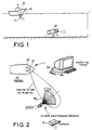
- One of the means to best guarantee safety is then to use a sonar located at the front of the building and to detect in an area located as far forward as possible with respect to the walking axis of the building, at a sufficient distance .
- ROV Remote Operating Vehicle
- the subject of the invention is a seabed exploration system making it possible to explore these seabed, minimizing the risks for the main building by using an autonomous vehicle controlled remotely, comprising only a minimum load since it does not carries only part of the sonar circuits.
- the autonomous vehicle advantageously without connecting wire, only carries the circuits and the transmitting antenna, the main building carrying the reception circuits, the assembly carrying a bistatic sonar.
- a seabed exploration system comprising an autonomous underwater vehicle comprising sonar emission means, associated with a main naval vessel, is characterized in that the sonar emission means on the autonomous vehicle comprise a transmitting antenna and a set of electronic circuits coupled to the antenna to form a directive and coded multi-channel transmission in a soundproof sector, and in that reception means are carried by the main building and comprise detection means to form a reception channel specialized with a wide lobe in bearing coupled to a set of reception circuits comprising means for separating the codes received.
- the transmitting antenna 11 is located on the front of the ROV perpendicular to its advancing axis.
- the direction of transmission of the central channel makes with the central axis of the reception lobe any angle except 180 ° but preferably between -90 ° and + 90 °. Indeed, the boat and the ROV cannot face each other, because in this case all the acoustic paths are close, which prohibits the formation of the image.
- This antenna 11 carried by the autonomous remote-controlled vehicle is formed of acoustic transducers, for example aligned and equidistant; the distance between transducers is chosen to reject the image lobes outside the useful insonified sector (indeed, these could not be separated on reception).
- This antenna forms channels so that each channel corresponds to a particular transmitted frequency.
- each transducer successively receives N frequencies, N being the number of channels, and each frequency is assigned for each transducer of a phase shift depending on the direction of the channel to be formed at this frequency.
- N being the number of channels
- each frequency is assigned for each transducer of a phase shift depending on the direction of the channel to be formed at this frequency.
- the block diagram of the transmission circuits 12 is shown in FIG. 3. They comprise a set 120 of local oscillators at frequencies f1, f2 ... f N whose outputs are connected to the corresponding inputs of a training circuit of channels 121.
- This circuit includes a set of phase shifters, a control input connected to the output of a processor 122 and outputs connected to power amplifiers 123.
- the processor 122 is also connected to the set of local oscillators.
- the output signals of the power amplifiers 123 are applied to the transducers T 1, ... T N of the antenna.
- the control of the phase shifts for the formation of the emission channels is ensured by the processor 122 receiving the yaw, roll and pitch parameters coming from sensor circuits 124 to effect electronic stabilization of the channels.
- the emission is therefore formed by a number of adjacent fine brushes insonating the space towards the bottom of the sea on a sector of angle ⁇ E.
- Each beam is particularized by its code (ie its frequency): the emission is said to be "colored” in frequency.
- the fan-shaped track directions cover the angle sectorani E with overlaps at 3dB.
- the electronic transmission circuits are entirely digital.
- the signal to be transmitted is first recorded in memories PROMs with the delays or phase shifts necessary for all the frequencies.
- the input of each power amplifier is connected to the output of a digital analog converter of circuit 121.
- the receiver carried by the boat is shown in FIG. 4. It comprises a broadband reception antenna made up of at least one hydrophone 21 of coefficient Q compatible with the frequency band to be passed. This band is determined by the desired distance resolution and it is a function of the frequencies transmitted.
- a specialized reception channel with a wide lobe in bearing is conventionally formed by a channel forming circuit 210.
- the angular width ⁇ R of the reception sector is determined to obtain, at the detection distance, an area sufficient land to cover the soundproof sector.
- the signal received in this channel is then filtered by a bank of bandpass filters 211; each filter being centered on one of the frequencies received.
- the filter bank is produced by fast Fourier transformation (FFT) of the signal.
- the doppler results in a shift in the frequencies transmitted as a function of the speeds of the boat and of the vehicle ROV and of the directions of emission and reception.
- the filters are slaved so as to always have a central frequency equal to the received frequency.
- a display console 212 makes it possible to display, from the detected signals, a representation of the soundproof zone.
- each pixel having its channel number on the abscissa and the distance D from the reflection point on the background to the ordinate relative to the phase center of the transmitting antenna 11.
- the heading, distance and altitude information of the autonomous vehicle ROV which are generally known, either for certain cases because they are fixed (altitude), or because they are given by the sonar detector. . It is also possible to use the knowledge of the instant of emission to overcome the knowledge of the distance; this instant is advantageously known in advance by the fact that the transmitter and the receiver, respectively on the ROV and the boat are provided with synchronous clocks. This information can also be transmitted acoustically by equipping the ROV with a beacon generating underwater pulses, coded so as to transmit the course of the transmitter (not shown). The distance is deducted from the journey time of the direct journey.
- the resolution on the bottom is 1.5 meters at 300m away.
- the number of channels formed N corresponds to the number of frequencies. If B is the transmitted band, the total band is NB and the coefficient Q of each sensor of the receiving antenna must not be less than f min / NB (f o being chosen as the mid frequency, f min : f o - NB / 2),
- a minimum coefficient Q is therefore chosen which is achievable for fixing the total band NB, B determining the resolution in distance.
- the distance resolution ⁇ d must be at least equal to ⁇ l.
- the number of transducers N E of the transmitting antenna is given by imposing a distance d between transducers such that, as indicated above, the image lobes are outside the insonified sector, that is to say: d ⁇ c / 2f max sin ( ⁇ E / 2)
- the transmission frequencies are equidistant and such that two successive frequencies are separated by at least B.
- the Fresnel distance is calculated to verify that it is compatible with the classification distance. If it is too large, it is necessary to focus on the broadcast. With a digital emission control method, that is to say with independent transducers controlled by PROMS, this focusing is possible and therefore makes it possible to work at very close distances.
- This focusing can be permanent if it is light because then it will not reduce the performance in detection on echo.
- the Fresnel distance is 11.2 meters and therefore there is no need to focus.
- the Fresnel distance is such that it is necessary to focus slightly on the emission.
- the invention is not limited to the embodiment described and shown.
- a so-called transmitting antenna "alternating quadrature phases" on the ROV can be used.
- Each transducer is offset by ⁇ / 2 compared to the previous one.
- the antenna By successively transmitting the frequencies in pulses of duration 1 / B, one obtains, as previously, channels at different frequencies. So that the central emission channel at f o is in line with the ROV, the antenna must be placed inclined by arcsin ( ⁇ / 4d) for the central frequency f o . This is however not compulsory.
- frequency coding requires dividing the reception frequency band by the number of channels, which has the drawback of limiting the distance resolution. An increase in the band in each channel would lead to too low an angular sector of emission ⁇ E.
- a first variant to increase band B consists of forming multiple channels at reception to angularly separate n groups of identical frequencies: thus, taking the previous example, three groups of seven different frequencies to form the 21 transmission channels are then issued; at reception three channels are formed at reception to cover the reception sector ⁇ R instead of one.
- This technique is limited by the fact that the classification distance must remain large enough to be able to separate angularly at reception the channels of the same frequency.
- the receiving sonar can only separate at most 1.5m at a distance of 300 m, which limits the factor n of increase in the band to a classification distance d c . For 15 meters, n is limited to 1.5 N / ⁇ l ⁇ 5 ..
- a second solution for increasing the band B consists in carrying out a time coding.
- the same signal is transmitted sequentially in the direction of the channels, the transmission being directive on site to limit the response time.
- the channel transmissions are shifted one by one by this duration and, on reception, the channel signals are separated in time. Directivity in elevation is obtained by a greater height of the emission transducers.
- Mixed time-frequency coding can also be implemented.
- the system can be completely independent of the sonar detector carried by the boat by receiving on a specialized transducer (hydrophone) for example cabinet. It can be towed.
- a specialized transducer for example cabinet. It can be towed.
- the system according to the invention makes it possible to carry out "high resolution” acoustic imaging at very large distances for the frequencies used, and this without any problem of data transmission.
- This system can be installed without difficulty on a small autonomous ROV vehicle since the transmitting antenna is quite small (29 cm at 200 kHz).
- the invention can be applied to an anti-mine missile (minekiller): it is a "one-way" device which carries a destruction charge.
- the vehicle being consumable, the on-board equipment must be limited to the maximum and moreover the resolution is all the better the closer the vehicle is to the target.
- the system which is the subject of the invention is particularly well suited to this application.
- An advantage of this structure, with colored multi-channel emission on the autonomous vehicle and, single-channel reception on the boat is that the resolution does not depend on the distance boat-soundproofed area, nor on the distance boat-autonomous vehicle.
- the receiver carried by the ship is preferably single-channel, it can be with a wide lobe and does not require stabilization.
- the only constraint is to direct a hydrophone in the approximate direction of the vehicle.
- This hydrophone can be mounted on the antenna of a mine hunting sonar or as described above use one or more of the transducers of the sonar antenna already installed.
Landscapes
- Engineering & Computer Science (AREA)
- Radar, Positioning & Navigation (AREA)
- Remote Sensing (AREA)
- Physics & Mathematics (AREA)
- Computer Networks & Wireless Communication (AREA)
- General Physics & Mathematics (AREA)
- Acoustics & Sound (AREA)
- Measurement Of Velocity Or Position Using Acoustic Or Ultrasonic Waves (AREA)
Claims (9)
- Explorationssystem für den Meeresgrund mit einem autonomen Unterseeboot (1), das Sonarsendemittel enthält und einem Hauptschiff (2) zugeordnet ist, dadurch gekennzeichnet, daß die Sonarsendemittel auf dem autonomen U-Boot eine Sendeantenne (11) und eine Gruppe von an die Antenne (11) gekoppelten elektronischen Schaltungen (12) aufweisen, um zahlreiche gerichtete und kodierte Strahlen in einem beschallten Azimutsektor auszusenden, und daß Empfangsmittel (21, 22) auf dem Hauptschiff montiert sind und Erfassungsmittel (21) enthalten, um einen spezialisierten Empfangskanal mit breiter Keule in Azimutrichtung zu bilden, der an eine Gruppe von Empfangsschaltungen (22) gekoppelt ist, welche Mittel (211) zur Trennung der empfangenen Kodes enthalten.
- System nach Anspruch 1, dadurch gekennzeichnet, daß die verschiedenen Kanalkodes Frequenzen sind.
- System nach einem der Ansprüche 1 und 2, dadurch gekennzeichnet, daß die Sendeantenne (11), die sich auf dem autonomen U-Boot (1) befindet, senkrecht zur Fortbewegungsachse des U-Boots liegt und daß die zentrale Achse des Empfangskanals mit der Fortbewegungsachse des autonomen U-Boots einen Winkel zwischen -90 und +90° einschließt.
- System nach Anspruch 2, dadurch gekennzeichnet, daß die Sendeantenne eine Gruppe von fluchtenden und in gleichem Abstand angeordneten Transduktoren aufweist, deren Abstand so gewählt ist, daß die Bildkeulen außerhalb des beschallten Sektors liegen, und daß die Transduktoren über eine Kanalbildungsschaltung (121) gesteuert werden, die von einem Prozessor (122) durch Signale überwacht wird, deren Phasen und Frequenzen vorgegebenen Gesetzen folgen, die von den Richtungen der bei den verschiedenen Kodefrequenzen zu bildenden Sendekanäle abhängt.
- System nach einem der Ansprüche 1 bis 4, dadurch gekennzeichnet, daß die elektronischen Sendeschaltungen digitale Schaltungen sind.
- System nach Anspruch 1, dadurch gekennzeichnet, daß die Empfangsschaltungen (22) eine Schaltung (210) zur Bildung einer breiten Empfangskeule aufweisen, die an die Trennmittel (211) gekoppelt sind, deren Ausgänge mit einem Anzeigepult (212) verbunden sind.
- Explorationssystem für den Meeresgrund mit einem autonomen Unterseeboot (1), das Sonarsendemittel enthält und einem Hauptschiff (2) zugeordnet ist, dadurch gekennzeichnet, daß die Sonarsendemittel auf dem autonomen U-Boot eine Sendeantenne (11) und eine Gruppe von an die Antenne (11) gekoppelten elektronischen Schaltungen (12) aufweist, um zahlreiche gerichtete und kodierte Strahlen in einem beschallten Azimutsektor zu bilden, und daß Empfangsmittel (21, 22) auf dem Hauptschiff montiert sind und Erfassungsmittel (21) zur Bildung einer begrenzten Anzahl von spezialisierten Empfangskanälen, typisch höchstens fünf Kanäle, mit breiter Keule in Azimutrichtung aufweisen, die an eine Gruppe von Empfangsschaltungen (22) gekoppelt sind, welche Mittel (211) zur Trennung der empfangenen Kodes enthalten, wobei die gleichen Gruppen von Kodes in benachbarten Gruppen von gerichteten Sendekanälen verwendbar sind.
- System nach Anspruch 7, dadurch gekennzeichnet, daß die Kanalkodes Frequenzen sind und eine Gruppe von Frequenzen auf der Sendeseite in benachbarten Gruppen von benachbarten Kanälen, die den beschallten Sektor überdecken, verwendet wird, wobei die identischen Frequenzen, die unterschiedlichen Sendekanälen zugeordnet sind, räumlich durch die Empfangskanäle unterschiedlicher Richtung mit breiter Keule voneinander getrennt werden.
- System nach einem der Ansprüche 1 und 7, dadurch gekennzeichnet, daß die Lage des autonomen U-Boots aufgrund der Ortsbestimmung einer Bake bekannt ist, die auf dem autonomen U-Boot befestigt ist und einen kodierten Impuls aussendet, der den Kurs des Senders überträgt.
Applications Claiming Priority (3)
| Application Number | Priority Date | Filing Date | Title |
|---|---|---|---|
| FR9108608A FR2679040B1 (fr) | 1991-07-09 | 1991-07-09 | Systeme d'exploration des fonds marins. |
| FR9108608 | 1991-07-09 | ||
| PCT/FR1992/000593 WO1993001505A1 (fr) | 1991-07-09 | 1992-06-26 | Systeme d'exploration des fonds marins |
Publications (2)
| Publication Number | Publication Date |
|---|---|
| EP0593532A1 EP0593532A1 (de) | 1994-04-27 |
| EP0593532B1 true EP0593532B1 (de) | 1996-02-28 |
Family
ID=9414877
Family Applications (1)
| Application Number | Title | Priority Date | Filing Date |
|---|---|---|---|
| EP92913355A Expired - Lifetime EP0593532B1 (de) | 1991-07-09 | 1992-06-26 | System für exploration des meeresbodens |
Country Status (5)
| Country | Link |
|---|---|
| EP (1) | EP0593532B1 (de) |
| CA (1) | CA2113195A1 (de) |
| DE (1) | DE69208662T2 (de) |
| FR (1) | FR2679040B1 (de) |
| WO (1) | WO1993001505A1 (de) |
Family Cites Families (4)
| Publication number | Priority date | Publication date | Assignee | Title |
|---|---|---|---|---|
| US4975887A (en) * | 1987-01-09 | 1990-12-04 | The United States Of America As Represented By The Secretary Of The Navy | Bistatic side scan sonar |
| GB2215281B (en) * | 1988-03-15 | 1992-01-22 | Plessey Co Plc | Improvements in or relating to minehunting systems |
| FR2643464B1 (fr) * | 1989-02-17 | 1991-06-14 | Thomson Csf | Procede pour augmenter la cadence image d'un sonar et sonar pour la mise en oeuvre de ce procede |
| US4924448A (en) * | 1989-03-09 | 1990-05-08 | Gaer Marvin C | Bistatic system and method for ocean bottom mapping and surveying |
-
1991
- 1991-07-09 FR FR9108608A patent/FR2679040B1/fr not_active Expired - Fee Related
-
1992
- 1992-06-26 DE DE69208662T patent/DE69208662T2/de not_active Expired - Fee Related
- 1992-06-26 WO PCT/FR1992/000593 patent/WO1993001505A1/fr not_active Ceased
- 1992-06-26 EP EP92913355A patent/EP0593532B1/de not_active Expired - Lifetime
- 1992-06-26 CA CA002113195A patent/CA2113195A1/fr not_active Abandoned
Also Published As
| Publication number | Publication date |
|---|---|
| CA2113195A1 (fr) | 1993-01-21 |
| FR2679040B1 (fr) | 1993-09-24 |
| EP0593532A1 (de) | 1994-04-27 |
| WO1993001505A1 (fr) | 1993-01-21 |
| FR2679040A1 (fr) | 1993-01-15 |
| DE69208662T2 (de) | 1996-07-18 |
| DE69208662D1 (de) | 1996-04-04 |
Similar Documents
| Publication | Publication Date | Title |
|---|---|---|
| EP3559697B1 (de) | System zur optimierten akustischen detektion zur detektion verschiedener unterwasserbedrohungen in einem empfindlichen bereich | |
| EP0084468B1 (de) | System zur akustischen Positionierung | |
| AU2004206560B2 (en) | Sonar array system | |
| CN112684482B (zh) | 一种基于海洋无人平台的水下目标探测系统及方法 | |
| EP0397547B1 (de) | Vermeidungssonar für Unterwasserobjekte unterhalb der Wasseroberfläche | |
| US10031216B2 (en) | Synthetic aperture sonar system for inspecting underwater surfaces | |
| EP3559696B1 (de) | Modulares verteiltes system zur akustischen erkennung von unterwasserbedrohungen in einem empfindlichen bereich | |
| EP2018579B1 (de) | Verbesserter frontalsonar | |
| EP1695115B1 (de) | Einrichtung zur vermeidung von hindernissen für ein schnelles wasserfahrzeug mit mehreren hüllen | |
| Pinto et al. | Real-and synthetic-array signal processing of buried targets | |
| Bjørnø | Developments in sonar and array technologies | |
| WO1990009600A1 (fr) | Procede pour augmenter la cadence image d'un sonar et sonar pour la mise en ×uvre de ce procede | |
| FR2589248A1 (fr) | Amelioration des systemes d'autoguidage acoustique de vehicules sous-marins | |
| EP0593532B1 (de) | System für exploration des meeresbodens | |
| Schock et al. | Synthetic aperture processing of buried object scanning sonar data | |
| EP0688437A1 (de) | Vorrichtung zum aufspüren im boden eingebetteter objekte | |
| FR2538124A1 (fr) | Systeme acoustique a antennes parametriques multifaisceaux | |
| FR2679041A1 (fr) | Systeme de detection d'objets sous-marins. | |
| CA2129753C (fr) | Procede de stabilisation et de formation de voies pour sonar et sonar pour sa mise en oeuvre | |
| WO2023031553A1 (fr) | Dispositif et procédé de détection et localisation d'objets immergés | |
| Bienvenu | Signal sonar processing | |
| FR2685782A1 (fr) | Procede de compensation du mouvement de l'antenne pour un sonar. | |
| FR2727520A1 (fr) | Systeme passif de detection de torpilles |
Legal Events
| Date | Code | Title | Description |
|---|---|---|---|
| PUAI | Public reference made under article 153(3) epc to a published international application that has entered the european phase |
Free format text: ORIGINAL CODE: 0009012 |
|
| 17P | Request for examination filed |
Effective date: 19931213 |
|
| AK | Designated contracting states |
Kind code of ref document: A1 Designated state(s): DE GB |
|
| 17Q | First examination report despatched |
Effective date: 19950622 |
|
| GRAA | (expected) grant |
Free format text: ORIGINAL CODE: 0009210 |
|
| AK | Designated contracting states |
Kind code of ref document: B1 Designated state(s): DE GB |
|
| REF | Corresponds to: |
Ref document number: 69208662 Country of ref document: DE Date of ref document: 19960404 |
|
| GBT | Gb: translation of ep patent filed (gb section 77(6)(a)/1977) |
Effective date: 19960509 |
|
| PLBE | No opposition filed within time limit |
Free format text: ORIGINAL CODE: 0009261 |
|
| STAA | Information on the status of an ep patent application or granted ep patent |
Free format text: STATUS: NO OPPOSITION FILED WITHIN TIME LIMIT |
|
| 26N | No opposition filed | ||
| REG | Reference to a national code |
Ref country code: GB Ref legal event code: IF02 |
|
| PGFP | Annual fee paid to national office [announced via postgrant information from national office to epo] |
Ref country code: GB Payment date: 20030625 Year of fee payment: 12 |
|
| PGFP | Annual fee paid to national office [announced via postgrant information from national office to epo] |
Ref country code: DE Payment date: 20030707 Year of fee payment: 12 |
|
| PG25 | Lapsed in a contracting state [announced via postgrant information from national office to epo] |
Ref country code: GB Free format text: LAPSE BECAUSE OF NON-PAYMENT OF DUE FEES Effective date: 20040626 |
|
| PG25 | Lapsed in a contracting state [announced via postgrant information from national office to epo] |
Ref country code: DE Free format text: LAPSE BECAUSE OF NON-PAYMENT OF DUE FEES Effective date: 20050101 |
|
| GBPC | Gb: european patent ceased through non-payment of renewal fee |
Effective date: 20040626 |