EP0593563B1 - Melkanlage mit positivem druck auf dünne zitzengummi - Google Patents
Melkanlage mit positivem druck auf dünne zitzengummi Download PDFInfo
- Publication number
- EP0593563B1 EP0593563B1 EP92914133A EP92914133A EP0593563B1 EP 0593563 B1 EP0593563 B1 EP 0593563B1 EP 92914133 A EP92914133 A EP 92914133A EP 92914133 A EP92914133 A EP 92914133A EP 0593563 B1 EP0593563 B1 EP 0593563B1
- Authority
- EP
- European Patent Office
- Prior art keywords
- pressure
- teat
- liner
- during
- negative pressure
- Prior art date
- Legal status (The legal status is an assumption and is not a legal conclusion. Google has not performed a legal analysis and makes no representation as to the accuracy of the status listed.)
- Expired - Lifetime
Links
- 210000002445 nipple Anatomy 0.000 claims description 229
- 239000008267 milk Substances 0.000 claims description 97
- 235000013336 milk Nutrition 0.000 claims description 97
- 210000004080 milk Anatomy 0.000 claims description 97
- 230000010349 pulsation Effects 0.000 claims description 90
- 210000000078 claw Anatomy 0.000 claims description 57
- 230000008859 change Effects 0.000 claims description 22
- 241000124008 Mammalia Species 0.000 claims description 16
- 238000000034 method Methods 0.000 claims description 13
- 230000007423 decrease Effects 0.000 claims description 12
- 230000003247 decreasing effect Effects 0.000 claims description 11
- 238000012864 cross contamination Methods 0.000 claims description 6
- 238000004891 communication Methods 0.000 claims description 4
- 230000001351 cycling effect Effects 0.000 claims 5
- 206010030113 Oedema Diseases 0.000 description 7
- 230000007704 transition Effects 0.000 description 6
- 230000009471 action Effects 0.000 description 5
- 125000004122 cyclic group Chemical group 0.000 description 5
- 229920001971 elastomer Polymers 0.000 description 5
- 241000283690 Bos taurus Species 0.000 description 4
- 238000011160 research Methods 0.000 description 4
- 230000017531 blood circulation Effects 0.000 description 3
- 235000013365 dairy product Nutrition 0.000 description 3
- 239000012530 fluid Substances 0.000 description 3
- 230000019989 milk ejection Effects 0.000 description 3
- 230000011514 reflex Effects 0.000 description 3
- 229920002799 BoPET Polymers 0.000 description 2
- 239000005041 Mylar™ Substances 0.000 description 2
- 230000000694 effects Effects 0.000 description 2
- 238000005259 measurement Methods 0.000 description 2
- 230000009467 reduction Effects 0.000 description 2
- 210000001519 tissue Anatomy 0.000 description 2
- 206010020649 Hyperkeratosis Diseases 0.000 description 1
- 239000004677 Nylon Substances 0.000 description 1
- 239000008280 blood Substances 0.000 description 1
- 210000004369 blood Anatomy 0.000 description 1
- 210000000481 breast Anatomy 0.000 description 1
- 230000006835 compression Effects 0.000 description 1
- 238000007906 compression Methods 0.000 description 1
- 238000011161 development Methods 0.000 description 1
- 230000018109 developmental process Effects 0.000 description 1
- 230000008030 elimination Effects 0.000 description 1
- 238000003379 elimination reaction Methods 0.000 description 1
- 238000005516 engineering process Methods 0.000 description 1
- 210000004907 gland Anatomy 0.000 description 1
- 208000015181 infectious disease Diseases 0.000 description 1
- 239000004816 latex Substances 0.000 description 1
- 229920000126 latex Polymers 0.000 description 1
- 210000002751 lymph Anatomy 0.000 description 1
- 208000004396 mastitis Diseases 0.000 description 1
- 238000012986 modification Methods 0.000 description 1
- 230000004048 modification Effects 0.000 description 1
- 229920001778 nylon Polymers 0.000 description 1
- 229920000573 polyethylene Polymers 0.000 description 1
- 230000004044 response Effects 0.000 description 1
- 230000003248 secreting effect Effects 0.000 description 1
- 238000007493 shaping process Methods 0.000 description 1
- 229910052710 silicon Inorganic materials 0.000 description 1
- 239000010703 silicon Substances 0.000 description 1
- 230000000638 stimulation Effects 0.000 description 1
- 230000008961 swelling Effects 0.000 description 1
Images


Classifications
-
- A—HUMAN NECESSITIES
- A01—AGRICULTURE; FORESTRY; ANIMAL HUSBANDRY; HUNTING; TRAPPING; FISHING
- A01J—MANUFACTURE OF DAIRY PRODUCTS
- A01J5/00—Milking machines or devices
- A01J5/007—Monitoring milking processes; Control or regulation of milking machines
-
- A—HUMAN NECESSITIES
- A01—AGRICULTURE; FORESTRY; ANIMAL HUSBANDRY; HUNTING; TRAPPING; FISHING
- A01J—MANUFACTURE OF DAIRY PRODUCTS
- A01J5/00—Milking machines or devices
- A01J5/04—Milking machines or devices with pneumatic manipulation of teats
- A01J5/08—Teat-cups with two chambers
Definitions
- the invention relates to a method and apparatus for milking mammals, including cows.
- Milking systems withdraw milk from the milk secreting glands of mammals by applying negative pressure, i.e. vacuum, to the teat.
- a plurality of teat cups are provided, each having a liner, or inflation, around a respective teat, and defining a milk flow passage within the liner below the teat, and a pulsation chamber outside the liner between the liner and the teat cup.
- the milk flow passage within the liner supplies milk to a milking claw which also receives milk from milk flow passages of other liners of other teat cups.
- the milking cycle has an on portion and an off portion. Milk is withdrawn from the teat through the liner to the claw during the on portion. During the off portion, the closed liner stops milk flow from the teat.
- a new combination is provided using positive pressure with a thin-walled floppy liner.
- Thin-walled floppy liners are known in the prior art, "Teat Cup and Claw” D.S.M. Phillips, Proceedings of Third Australian Machine Milking Conference, Hobart, Moet, Columbia, 1965, pages 132-143.
- the use of positive pressure in the milking cycle is also known in the prior art: “Proceedings of the Symposium on Machine Milking 1968" G. Wehowski, The National Institute for Research in Dairying, Shinfield, Reading, England, 1969, pages 134-135; "Responses of the Bovine Teat to Machine Milking: Measurement of Changes in Thickness of the Teat Apex", Jorn Hamann and Graeme A.
- the liner is a thin-walled floppy member substantially conforming its shape to the teat, and of itself providing substantially no load on the teat.
- a similar compressive load is applied to all the teats irrespective of their shape and size when the liner is compressed in each pulsation cycle.
- the cyclic compressive load is applied uniformly over most of the teat surface and controlled at a predetermined physiologically acceptable level by the pressure in the pulsation chamber.
- a controlled cyclic pressure may be applied to the lower tip of the teat and along the barrel of the teat thereabove by means of a thin-walled floppy liner, and blood circulation is maintained at a physiologically acceptable level within the walls of the teat barrel as well as the teat lower tip.
- the combination of controlled positive pressure and of a second negative pressure to the pulsation chamber, the latter providing a lesser vacuum than a first negative pressure supplied to the milk flow passage defined by the liner, and a thin non-distensible liner minimizes congestion, oedema, and damage to the lower tip of the teat. Teats are softer after milking, and teat condition is improved.
- a thin-walled floppy liner is operated as a pressure switch limiting the amount of negative pressure applied to the lower tip of the teat.
- a negative first pressure is applied through the claw to the milk flow passage at the lower end of the liner.
- Pressure in the pulsation chamber is decreased during the on portion of the milking cycle to a negative second pressure.
- the second pressure is greater than the first pressure.
- the thin-walled floppy liner is closed and blocks communication of the negative first pressure to the lower tip of the teat and limits the amount of negative pressure applied to the lower tip of the teat to the noted negative second pressure acting on the thin-walled floppy liner engaging the lower tip of the teat.
- Milk flow from the lower tip of the teat within the thin-walled floppy liner increases the pressure within the thin-walled floppy liner to equalize and slightly exceed the pressure in the pulsation chamber outside the thin-walled floppy liner to slightly open the milk flow passage until milk flow from the lower tip of the teat decreases to reduce the pressure within the thin-walled floppy liner such that the latter closes.
- the pressure in the pulsation chamber is increased during the off portion of the milking cycle to said positive pressure to collapse the thin-walled floppy liner and tightly close the milking passage and to apply the positive pressure along the teat by acting on the thin-walled floppy liner engaging the teat.
- the invention reduces the chances of cross-contamination between teats.
- the liner opens and closes, there is a volume change within the liner below the teat which displaces and moves air back and forth. This volume change and air movement raises the possibility of cross-contamination from another teat through the claw. Thus, infection of one teat may spread to other teats.
- the present invention only partially opens the liner with minimum volume change below the teat to permit milk flow, which minimum volume change below the teat reduces the chances of cross-contamination from another teat.
- the invention enables the noted partial opening of the liner without resorting to hydraulic milking, "Hydraulic Milking-Control Within The Teat-Cup", R.J.
- the present invention enables the noted partial opening of the liner while still using a conventional vacuum system wherein a substantially constant vacuum (first negative pressure) is applied through the claw to the interior of the lower end of the liner throughout the milking cycle.
- first negative pressure substantially constant vacuum
- second negative pressure differential pressure is applied across the liner during the on portion of the milking cycle such that the liner only partially opens, with minimum volume change within the liner below the teat, but enough to permit milk flow.
- FIG. 1 shows a milking system 10 having a plurality of teat cups such as 12, 14 connected to respective teats such as 16, 18 depending from the udder 20 of a mammal 22 such as a cow.
- Each teat cup has a liner or inflation such as 24, 26 around a respective teat and defining a milk flow passage such as 28, 30 within the liner below the teat, and a pulsation chamber such as 32, 34 outside the liner between the liner and the teat cup.
- the teat cup and liner are shown and described in U.S. Patent 4,530,307.
- a milking claw 36 for example as shown in U.S.
- Patent 4,537,152 has a plurality of inlets receiving milk through tubes such as 38, 40 connected to respective teat cups to receive milk from respective milk flow passages such as 28, 30.
- the claw has a discharge tube 42 connected to milk collection container 44 having a vacuum connection tube 46 connected to a source of negative pressure 48.
- Negative pressure source 48 applies substantially constant negative pressure (vacuum), relative to atmospheric pressure, through claw 44 to milk flow passages 28, 30.
- the system has a milking cycle with an on portion and an off portion. Milk flows from the teat towards claw 36 during the on portion.
- a pulsator valve 50 is connected to each of the teat cups at a connection tube such as 52 and has first and second conditions alternately and cyclically connecting the teat cup to the negative pressure source 48 through connection tube 54 during the on portion of the milking cycle, and connecting the teat cup to atmosphere through connection tube 56 during the off portion of the milking cycle. It is also known in the prior art to connect the teat cup to a source of positive pressure, relative to atmospheric pressure, during the off portion of the milking cycle, e.g. by supplying connection tube 56 with a source of positive pressure.
- connection tube 56, valve 50, and connection tube 52 to pulsation chamber 32 of teat cup 12 collapses and closes liner 24 below teat 16 to block milk flow, and to relieve the teat from the negative pressure applied from source 48 through connection tube 46, container 44, connection tube 42, claw 36, and connection tube 38 to milk flow passage 28 at the lower end of liner 24.
- negative pressure from source 48 is applied through connection tube 54, valve 50, and connection tube 52 to pulsation chamber 32 of teat cup 12, such that liner 24 opens to its normally open position and milk is withdrawn from teat 16.
- the pressure in pulsation chamber 32 is shown at solid line 58, and the pressure supplied through claw 36 to the interior of liner 28 is shown at dashed line 60.
- the period of the milking cycle is about 1 to 1.3 seconds.
- the pressure in pulsation chamber 32 is at atmospheric pressure, i.e. zero relative to atmosphere, as shown at 62.
- pulsator valve 50 is switched to its alternate condition, connecting negative pressure source 48 through connection tube 54, valve 50, and connection tube 52 to pulsation chamber 32, such that the pressure in pulsation chamber 32 falls as shown at 64, FIG.
- FIG. 4 shows the pressure applied to the lower tip of the teat at solid line 74, and the pressure supplied from source 44 at dashed line 76, over an interval of about four to five minutes.
- the milk flow increases the pressure, i.e. reduces the vacuum, in milk flow passage 28 within liner 24.
- These changes tend to reduce the milking rate, because of the lesser vacuum, and increase teat congestion and oedema at or near the end of milking at 80 because the pressure drops again, i.e. vacuum level rises again, as the milk flow rate decreases.
- FIGS. 5-13 illustrate the present invention and use like reference numerals from FIGS. 1-4 where appropriate to facilitate understanding.
- the present invention uses a thin-walled non-distensible floppy liner 82, FIG. 6, such as Mylar (tradename) having a wall thickness of about 0.1 to 1.0 millimeter.
- the upper end of the liner is around teat 16, and the lower end of the liner communicates through connection tube 38 with milking claw 36.
- Liner 82 substantially conforms its shape to teat 16, and of itself provides substantially no load on the teat.
- Liner 82 on teat 16 defines milk flow passage 84 within the liner and pulsation chamber 32 outside the liner between the liner and teat cup 12.
- connection tube 46, container 44, connection tube 42, claw 36, and connection tube 38 applies negative pressure, relative to atmospheric pressure, through connection tube 46, container 44, connection tube 42, claw 36, and connection tube 38 to milk flow passage 84 in the interior of the lower end of liner 82.
- the milking cycle has an on portion and an off portion. Milk is withdrawn from the teat during the on portion.
- the milking cycle is implemented by alternately and cyclically applying positive and negative pressure, relative to atmospheric pressure, to pulsation chamber 32, to implement the off and on portions, respectively.
- the present system collapses and closes liner 82 below the teat to block milk flow during the off portion of the milking cycle, FIG. 8, as in the prior art.
- the present method only partially opens liner 82, with minimum volume change below teat 16, to permit milk flow.
- Liner 82 is then collapsed and closed, FIGS. 7 and 8, and the cycle repeats.
- the minimum volume change within the liner below the teat, FIG. 6, reduces the chances of cross-contamination from another teat through claw 36.
- pressure in pulsation chamber 32 is increased during the off portion of the milking cycle to increase the pressure applied to the teat and collapse and close liner 82 below teat 16, as shown at the transition stage in FIG. 7, and the fully closed stage in FIG. 8.
- the pressure in pulsation chamber 32 is decreased during the on portion of the milking cycle to decrease the pressure applied to the teat and to permit partial opening of liner 82 with minimum volume change within liner 82 below the teat.
- a differential pressure is provided across liner 82 during the on portion of the milking cycle by a second negative pressure source 86, FIG. 5, such that the pressure in pulsation chamber 32 during the on portion of the milking cycle is greater than the pressure supplied through claw 36 by negative pressure source 48.
- the negative pressure from source 86 is supplied through connection tube 88, valve 50, and connection tube 52 to pulsation chamber 32.
- the negative pressure supplied by source 48 is typically in the range of about -40 to -50 kPa and is substantially constant, i.e. does not vary by more than about 5 or 6 kPa.
- the differential pressure applied across liner 82 during the on portion of the milking cycle is in the range of about 3 to 10 kPa, i.e. the minimum pressure in pulsation chamber 32 during the on portion of the milking cycle is about 3 to 10 kPa above the pressure supplied through claw 36, FIG.
- Pressure sources 48 and 86 may be connected by a regulator valve if desired to establish the relative differential pressure therebetween in the noted preferred range. Further alternatively, such regulator valve would enable elimination of second pressure source 86, if desired, i.e. would enable pressure source 48 to perform both of the noted first and second pressure source functions.
- valve 50 is in its off condition, and positive pressure, relative to atmospheric pressure, is supplied from pressure source 90 through connection tube 92, valve 50, and connection tube 52 to pulsation chamber 32.
- the maximum pressure in pulsation chamber 32 during the off portion of the milking cycle is in the range of about 10 to 20 kPa above atmospheric pressure.
- FIG. 7 shows a transitional stage in the milking cycle with pulsation chamber 32 at atmospheric pressure.
- FIG. 8 shows the off portion of the milking cycle with the teat canal 94 closed, the teat sinus 96 occluded, and substantially the entire length of the teat barrel flattened by the closed liner 82.
- the application of positive pressure to the pulsation chamber in the noted range during the off portion of the milking cycle in combination with the noted thin-walled non-distensible floppy liner provides a controlled cyclic pressure applied to the lower tip of the teat and along the barrel of the teat thereabove and maintains blood circulation at a physiologically acceptable level within the walls of the teat barrel as well as at the teat lower tip.
- the combination of controlled positive pressure and a thin non-distensible liner minimizes congestion, oedema and damage to the lower tip of the teat. Teats are softer after milking, and teat condition is improved.
- the liner be non-distensible, such as mylar.
- Alternatives include a thin elastic inner liner, e.g. silicon, latex, or polythene film, coated or supported by an outer nondistensible sleeve, e.g. nylon mesh. Outer sleeves are shown in U.S. Patents 3,096,740 and 4,315,480.
- FIG. 9 the pressure in pulsation chamber 32 in FIGS. 5-8 is shown at solid line 98, and the pressure supplied through claw 36 to the interior of liner 82 is shown at dashed line 100.
- the period of the milking cycle may be longer than the prior art, for example about 1 to 2 seconds.
- pulsator valve 50 is in a given condition connecting pressure source 90 through connection tube 92, valve 50, and connection tube 52 to pulsation chamber 32, and the pressure in pulsation chamber 32 is +10 kPa as shown at 102, i.e. 10 kPa above atmospheric pressure.
- pulsator valve 50 is switched to its alternate condition, connecting negative pressure source 86 through connection tube 88, valve 50, and connection tube 52 to pulsation chamber 32, such that the pressure in pulsation chamber 32 falls as shown at 104, FIG. 9, to level 106 Which is -40 kPa, i.e. 40 kPa below atmospheric pressure.
- level 106 which is -40 kPa, i.e. 40 kPa below atmospheric pressure.
- pulsator valve 50 is switched back to its other position, to connect positive pressure source 90 through connection tube 92, valve 50, and connection tube 52 to pulsation chamber 32, such that the pressure in pulsation chamber 32 rises as shown at 108 to +10 kPa as shown at 110, and the cycle is repeated.
- FIG. 10 shows the pressure applied to the teat at solid line 112, and the pressure supplied through claw 36 at dashed line 114, over an interval of about four to five minutes. Comparing FIG. 10 with FIG. 4, it is seen that in FIG. 10 there is no change in the average pressure applied to the teat as there is in FIG. 4, and hence no reduction in milking rate because of lesser vacuum, nor increased teat congestion and oedema near the end of milking otherwise due to a pressure drop as at 80 in FIG. 4.
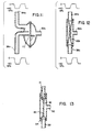
- Thin-walled floppy liner 82 is operated as a pressure switch limiting the amount of negative pressure applied to the lower tip of teat 16. This is illustrated in FIGS. 11-13.
- a negative pressure of -50 kPa is applied at connection tube 38a on one side of rubber diaphragm 82a
- a negative pressure of -40 kPa is applied at connection tube 52a on the other side of rubber diaphragm 82a.
- connection tube 38a When the negative pressure in connection tube 38a reaches -40 kPa, the pressure differential on rubber diaphragm 82a is equalized, and any further reduction in pressure in connection tube 38a draws rubber diaphragm 82a downwardly to engage and seal the upper end 112 of connection tube 38a, and hence block communication of such further decreasing pressure in tube 38a from reaching passage 84a.
- the minimum pressure in passage 84a is -40 kPa.
- FIG. 12 illustrates the same limiting pressure switch action but using a thin floppy liner or sleeve 82b in place of rubber diaphragm 82a.
- FIG. 13 shows the pressure switch action of FIG. 12 in conjunction with teat 16, with -50 kPa being supplied by connection tube 38 to milk flow passage 84 in liner 82, and with the pressure being supplied through connection tube 52 to pulsation chamber 32 varying between +10 kPa and -40 kPa, FIGS. 9 and 10.
- the pressure switch action of thin floppy liner 82 limits the amount of negative pressure applied to the lower tip of teat 16.
- the pressure in pulsation chamber 32 is decreased, 104, FIG. 9, during the on portion of the milking cycle to -40 kPa at level 106, such that liner 82 closes and blocks the -50 kPa pressure supplied through milking claw 36 and connection tube 38 from reaching the lower tip of the teat, and instead limits the amount of negative pressure applied to the lower tip of the teat to the -40 kPa pressure acting on thin-walled floppy liner 82 engaging the lower tip of the teat.
- Milk flow from the lower tip of the teat through milk flow passage 84 within liner 82 increases the pressure within the liner to equalize and slightly exceed the pressure in pulsation chamber 32 outside the liner to slightly open milk flow passage 84 until milk flow from the lower tip of the teat decreases to reduce the pressure within the liner such that the latter closes.
- the -50 kPa and the -40 kPa pressures provide differential pressure across the thin-walled floppy liner during the on portion of the milking cycle.
- the pressure in pulsation chamber 32 is increased, 108, FIG.
Landscapes
- Life Sciences & Earth Sciences (AREA)
- Animal Husbandry (AREA)
- Environmental Sciences (AREA)
- External Artificial Organs (AREA)
- Infusion, Injection, And Reservoir Apparatuses (AREA)
- Massaging Devices (AREA)
Claims (23)
- Verfahren zum Melken eines Säugers, mit den Schrittendes Anordnens eines Zitzenbechers (12, 14) mit einer Auskleidung (82) um eine Zitze (16, 18) des Säugers, wobei innerhalb der Auskleidung ein Milchflußweg und außerhalb der Auskleidung zwischen der Auskleidung und dem Zitzenbecher eine Pulsationskammer (32, 34) festgelegt ist, und wobei die Auskleidung ihre Form im wesentlichen der Zitze anpaßt;des Zuführens eines ersten negativen Drucks relativ zum Atmosphärendruck zum Milchflußweg;des Durchführens eines Melkzyklusses mit einem Ein-Abschnitt und einem Aus-Abschnitt, wobei wahrend des Ein-Abschnitts Milch von der Zitze (16, 18) zugeführt wird; unddes Ausführens des Melkzyklusses durch abwechselndes und zyklisches Anlegen eines positiven und eines zweiten negativen Drucks relativ zum Atmosphärendruck an die Pulsationskammer (32, 34), um die Aus- und Ein-Abschnitte auszuführen,
dadurch gekennzeichnet, daß die Auskleidung ein dünnwandiges biegsames Element (82) ist, das selbst im wesentlichen keine Last auf die Zitze ausübt, wobei der positive Druck gleichmäßig längs der Zitze einschließlich der unteren Spitze der Zitze und dem Schaft der Zitze über der unteren Spitze angelegt wird, und wobei der zweite negative Druck ein geringeres Vakuum ergibt als der erste negative Druck, so daß sich die Auskleidung während des Ein-Abschnitts des Melkzyklusses nur teilweise öffnet. - Verfahren nach Anspruch 1, wobei der maximale positive Druck in der Pulsationskammer (32, 34) während des Aus-Abschnitts des Melkzyklusses im Bereich von etwa 10 bis 20 kPa über dem Atmosphärendruck liegt.
- Verfahren zum Melken eines Säugers nach Anspruch 1, mitdem Versehen der dünnwandigen biegsamen Auskleidung (82) mit einem oberen Ende, das um die Zitze gelegt werden kann, und mit einem unteren Ende, das mit einem Milchsammelstück (36) in Verbindung steht und das innerhalb der Auskleidung einen Milchflußweg (84) festlegt;dem Zuführen des ersten negativen Drucks durch das Sammelstück zum Milchflußweg am unteren Ende der Auskleidung;dem Erzeugen des Melkzyklusses, bei dem während des Ein-Abschnitts Milch von der unteren Spitze der Zitze durch den Milchflußweg (84) zum Sammelstück geführt wird, und bei dem während des Aus-Abschnitts die Auskleidung (82) kollabiert und sich schließt, um den Milchfluß zu blockieren; und mitdem Betreiben der dünnwandigen biegsamen Auskleidung (82) als Druckschalter, der das Ausmaß des negativen Drucks begrenzt, das an die untere Spitze der Zitze angelegt wird, durchVerringern des Drucks in der Pulsationskammer (32, 34) während des Ein-Abschnitts des Melkzyklusses auf den zweiten negativen Druck derart, daß die dünnwandige biegsame Auskleidung (82) sich schließt und die Zuführung des ersten negativen Drucks zu der unteren Spitze der Zitze (16, 18) verhindert und das Ausmaß des negativen Drucks, der an die untere Spitze der Zitze angelegt wird, auf den zweiten negativen Druck begrenzt, der auf die dünnwandige biegsame Auskleidung (82) einwirkt, die mit der unteren Spitze der Zitze in Eingriff ist, wobei der Milchfluß von der unteren Spitze der Zitze innerhalb der dünnwandigen biegsamen Auskleidung den Druck in der dünnwandigen biegsamen Auskleidung ansteigen läßt, um den Druck in der Pulsationskammer außerhalb der dünnwandigen biegsamen Auskleidung auszugleichen und leicht zu übersteigen, um den Milchflußweg (84) leicht zu öffnen, bis der Milchfluß von der unteren Spitze der Zitze (16, 18) abnimmt und sich der Druck in der dünnwandigen biegsamen Auskleidung (82) derart verringert, daß sich diese schließt, wobei der erste und der zweite negative Druck während des Ein-Abschnitts des Melkzyklusses einen Differenzdruck über die dünnwandige biegsame Auskleidung erzeugt mit einem Druck in der Pulsationskammer, der größer ist als der Druck, der durch das Sammelstück zugeführt wird, undErhöhen des Drucks in der Pulsationskammer (32, 34) während des Aus-Abschnitts des Melkzyklusses auf den positiven Druck relativ zum Atmosphärendruck, damit die dünnwandige biegsame Auskleidung kollabiert und den Milchflußweg (84) eng verschließt, und um den positiven Druck längs der Zitze durch Einwirken auf die dünnwandige biegsame Auskleidung (82), die mit der Zitze in Eingriff steht, anzulegen, wobei der positive Druck gleichmäßig längs der Zitze einschließlich der unteren Spitze der Zitze und dem Schaft der Zitze über der unteren Spitze angelegt wird.
- Verfahren nach einem der vorstehenden Ansprüche, wobei die Differenz zwischen dem ersten und dem zweiten negativen Druck im Bereich von etwa 3 bis 10 kPa liegt.
- Verfahren nach Anspruch 4, wobei der positive Druck im Bereich von etwa 10 bis 20 kPa über dem Atmosphärendruck liegt und der erste negative Druck im Bereich von etwa 40 bis 50 kPa unter dem Atmosphärendruck.
- Verfahren zum Melken eines Säugers nach Anspruch 1, mit dem Bereitstellen einer Anzahl der Zitzenbecher (12, 14) mit jeweils einer Auskleidung (82) um eine der Zitzen (16, 18) des Säugers (22), wobei innerhalb der Auskleidung unter der Zitze ein Milchflußweg (84) und außerhalb der Auskleidung zwischen der Auskleidung und dem Zitzenbecher eine Pulsationskammer (32, 34) festgelegt ist, und wobei der Milchflußweg (84) in der Auskleidung die Milch einem Milchsammelstück (36) zuführt, das auch die Milch von den Milchflußwegen (84) anderer Auskleidungen in anderen Zitzenbechern aufnimmt;dem im wesentlichen konstanten Zuführen des ersten negativen Drucks durch das Sammelstück (36) zu den Milchflußwegen (84);dem Kollabieren und Schließen jeder Auskleidung (82) unter den Zitzen (16, 18) zum Blockieren des Milchflusses und dann einem nur teilweisen Öffnen jeder der Auskleidungen mit einer minimalen Volumenänderung unter der Zitze, um den Milchfluß zu ermöglichen, dann dem Kollabieren und Schließen jeder der Auskleidungen und Wiederholen des Zyklusses, wobei die minimale Volumenänderung unter den Zitzen die Gefahr einer Kreuzkontamination von einer anderen Zitze verringert.
- Verfahren nach Anspruch 6, mitdem Erhöhen des Drucks in jeder der Pulsationskammern während des Aus-Abschnitts des Melkzyklusses auf den positiven Druck, um den Druck zu erhöhen, der an die Zitzen angelegt wird, damit jede der Auskleidungen unter den Zitzen kollabiert und sich schließt;dem Verringern des Drucks in jeder der Pulsationskammern während des Ein-Abschnitts des Melkzyklusses auf den zweiten negativen Druck, um den Druck zu verringern, der an die Zitzen angelegt wird, damit das teilweise Öffnen jeder der Auskleidungen mit einer minimalen Volumenänderung unter den Zitzen möglich ist;dem Vorsehen eines Differenzdrucks über die Auskleidung (82) während des Ein-Abschnitts des Melkzyklusses, wobei der zweite negative Druck in jeder der Pulsationskammern (32, 34) größer ist als der im wesentlichen konstante erste negative Druck, der durch das Sammelstück (36) zugeführt wird.
- Verfahren nach Anspruch 7, mit dem Anlegen des Differenzdrucks während des Ein-Abschnitts des Melkzyklusses derart, daß der minimale zweite negative Druck in jeder der Pulsationskammern (32, 34) im Bereich von etwa 3 bis 10 kPa über dem im wesentlichen konstanten ersten negativen Druck liegt, der durch das Sammelstück (36) angelegt wird.
- Verfahren nach Anspruch 8, wobei der maximale positive Druck in jeder der Pulsationskammern (32, 34) während des Aus-Abschnitts des Melkzyklusses im Bereich von etwa 10 bis 20 kPa über dem Atmosphärendruck liegt und der im wesentlichen konstante erste negative Druck, der durch das Sammelstück (36) zugeführt wird, im Bereich von etwa 40 bis 50 kPa unter dem Atmosphärendruck.
- Verfahren zum Melken eines Säugers nach Anspruch 1, mitdem Bereitstellen einer Anzahl der Zitzenbecher (12, 14) mit jeweils einer Auskleidung (82) um eine der Zitzen (16, 18) des Säugers, wobei innerhalb der Auskleidung unter der Zitze ein Milchflußweg (84) und außerhalb der Auskleidung zwischen der Auskleidung und dem Zitzenbecher eine Pulsationskammer (32, 34) festgelegt ist, wobei jede der Auskleidungen (82) ein dünnwandiges biegsames Element (82) ist, das seine Form im wesentlichen der Zitze anpaßt und das selbst im wesentlichen keine Last auf die Zitze ausübt, und wobei die Milchflußwege die Milch dem Milchsammelstück (36) zuführen;dem im wesentlichen konstanten Zuführen des ersten negativen Drucks durch das Sammelstück zu den Milchflußwegen (84);dem Vorsehen eines Melkzyklusses mit einem Ein-Abschnitt und einem Aus-Abschnitt, wobei die Milch während des Ein-Abschnitts dem Sammelstück zugeführt wird, und dem Ausführen des Melkzyklusses durch, für jeden der Zitzenbecher (12, 14),Erhöhen des Drucks in der Pulsationskammer (32, 34) während des Aus-Abschnitts des Melkzyklusses auf den positiven Druck, um den an die Zitze angelegten Druck zu erhöhen, damit die Auskleidung (82) unter der Zitze kollabiert und sich vollständig schließt, wobei der positive Druck gleichmäßig längs der Zitze einschließlich der unteren Spitze der Zitze und dem Schaft der Zitze über der unteren Spitze angelegt wird,Verringern des Drucks in der Pulsationskammer (32, 34) während des Ein-Abschnitts des Melkzyklusses auf den zweiten negativen Druck, um den Druck zu verringern, der an die Zitze angelegt wird, wobei jedoch ein Differenzdruck über die Auskleidung (82) derart erzeugt wird, daß der Druck in der Pulsationskammer größer ist als der im wesentlichen konstante erste negative Druck, der durch das Sammelstück (36) zugeführt wird, derart, daß der Druck in der Pulsationskammer während des Ein-Abschnitts des Melkzyklusses ein geringeres Vakuum ergibt als das Vakuum, das durch den im wesentlichen konstanten negativen Druck erzeugt wird, der durch das Sammelstück (36) zugeführt wird, derart, daß die Auskleidung sich mit einer minimalen Volumenänderung unter der Zitze nur teilweise öffnet; unddas erneute Erhöhen des Drucks in der Pulsationskammer (32, 34) und das Wiederholen des Zyklusses.
- Verfahren nach Anspruch 10, wobeider erste negative Druck, der durch das Sammelstück (36) zugeführt wird, im Bereich von etwa 40 bis 50 kPa unter dem Atmosphärendruck liegt;der maximale positive Druck in jeder der Pulsationskammern (32, 34) während des Aus-Abschnitts des Melkzyklusses im Bereich von etwa 10 bis 20 kPa über dem Atmosphärendruck liegt,der minimale zweite negative Druck in jeder der Pulsationskammern (32, 34) während des Ein-Abschnitts des Melkzyklusses im Bereich von etwa 3 bis 10 kPa über dem ersten negativen Druck liegt, der durch das Sammelstück (36) zugeführt wird, um während des Ein-Abschnitts des Melkzyklusses den Differenzdruck an jeder der Auskleidungen (82) zu erzeugen.
- Vorrichtung zum Melken eines Säugers, miteinem Zitzenbecher (12, 14) mit einer Auskleidung (82) um eine Zitze (16, 18) des Säugers, wobei innerhalb der Auskleidung ein Milchflußweg (84) und außerhalb der Auskleidung zwischen der Auskleidung und dem Zitzenbecher eine Pulsationskammer (32, 34) festgelegt ist, und wobei die Auskleidung ihre Form im wesentlichen der Zitze anpaßt;einer Einrichtung (48) zum Zuführen eines ersten negativen Drucks relativ zum Atmosphärendruck zum Milchflußweg; und miteiner Zykluseinrichtung (50) zum Durchführen eines Melkzyklusses mit einem Ein-Abschnitt und einem Aus-Abschnitt, wobei während des Ein-Abschnitts Milch von der Zitze zugeführt wird; und mit einer Einrichtung (50), die abwechselnd und zyklisch einen positiven und einen zweiten negativen Druck relativ zum Atmosphärendruck an die Pulsationskammer anlegt, um die Aus- und Ein-Abschnitte auszuführen,
dadurch gekennzeichnet, daß die Auskleidung ein dünnwandiges biegsames Element (82) ist, das selbst im wesentlichen keine Last auf die Zitze ausübt, wobei der positive Druck längs der Zitze einschließlich der unteren Spitze der Zitze und dem Schaft der Zitze über der unteren Spitze angelegt wird, und wobei der zweite negative Druck ein geringeres Vakuum ergibt als der erste negative Druck, so daß sich die Auskleidung während des Ein-Abschnitts des Melkzyklusses nur teilweise öffnet. - Vorrichtung nach Anspruch 12, wobei die Zykluseinrichtung (50), die abwechselnd und zyklisch den positiven und negativen Druck an die Pulsationskammer (32, 34) anlegt, während des Aus-Abschnitts des Melkzyklusses einen maximalen positiven Druck in der Pulsationskammer im Bereich von etwa 10 bis 20 kPa über dem Atmosphärendruck erzeugt.
- Vorrichtung nach Anspruch 12, wobei die Auskleidung ein oberes Ende, das um die Zitze gelegt werden kann, und ein unteres Ende aufweist, das mit einem Milchsammelstück (36) in Verbindung steht und das innerhalb der dünnwandigen biegsamen Auskleidung den Milchflußweg (84) festlegt,
wobei die Einrichtung zum Zuführen eines ersten negativen Drucks zum Milchflußweg (84) den Druck durch das Sammelstück (36) zum Milchflußweg am unteren Ende der dünnwandigen biegsamen Auskleidung (82) führt,
wobei die Milch während des Ein-Abschnitts durch den Milchflußweg zum Sammelstück geführt wird, und wobei während des Aus-Abschnitts die dünnwandige biegsame Auskleidung (82) kollabiert und sich schließt, um den Milchfluß zu blockieren, wobei die Vorrichtung ferner umfaßteine Einrichtung zum Betreiben der dünnwandigen biegsamen Auskleidung als Druckschalter, der das Ausmaß des negativen Drucks begrenzt, das an die untere Spitze der Zitze angelegt wird, miteiner Einrichtung (86) zum Anlegen des zweiten negativen Drucks an die Pulsationskammer (32, 34) während des Ein-Abschnitts des Melkzyklusses derart, daß die dünnwandige biegsame Auskleidung (82) sich schließt und die Zuführung des ersten negativen Drucks zu der unteren Spitze der Zitze verhindert und das Ausmaß des negativen Drucks, der an die untere Spitze der Zitze angelegt wird, auf den zweiten negativen Druck begrenzt, der auf die dünnwandige biegsame Auskleidung (82) einwirkt, die mit der unteren Spitze der Zitze in Eingriff ist, wobei der Milchfluß von der unteren Spitze der Zitze innerhalb der dünnwandigen biegsamen Auskleidung (82) den Druck in der dünnwandigen biegsamen Auskleidung (82) ansteigen läßt, um den Druck in der Pulsationskammer außerhalb der dünnwandigen biegsamen Auskleidung auszugleichen und leicht zu übersteigen, um den Milchflußweg (84) leicht zu öffnen, bis der Milchfluß von der unteren Spitze der Zitze abnimmt und sich der Druck in der dünnwandigen biegsamen Auskleidung (82) derart verringert, daß sich diese schließt, wobei der erste und der zweite negative Druck während des Ein-Abschnitts des Melkzyklusses einen Differenzdruck über die dünnwandige biegsame Auskleidung (82) erzeugt mit einem Druck in der Pulsationskammer (32, 34), der größer ist als der Druck, der durch das Sammelstück (36) zugeführt wird, und miteiner Einrichtung (90) zum Anlegen des positiven Drucks relativ zum Atmosphärendruck an die Pulsationskammer (32, 34) während des Aus-Abschnitts des Melkzyklusses, damit die dünnwandige biegsame Auskleidung (82) kollabiert und sich schließt und den Milchflußweg (84) eng verschließt, und um den positiven Druck längs der Zitze durch Einwirken auf die dünnwandige biegsame Auskleidung (82), die mit der Zitze in Eingriff steht, anzulegen, wobei der positive Druck gleichmäßig längs der Zitze einschließlich der unteren Spitze der Zitze und dem Schaft der Zitze über der unteren Spitze angelegt wird. - Vorrichtung nach Anspruch 14, wobei die Differenz zwischen dem ersten und dem zweiten negativen Druck im Bereich von etwa 3 bis 10 kPa liegt.
- Vorrichtung nach Anspruch 15, wobei der positive Druck im Bereich von etwa 10 bis 20 kPa über dem Atmosphärendruck liegt und der erste negative Druck im Bereich von etwa 40 bis 50 kPa unter dem Atmosphärendruck.
- Vorrichtung nach Anspruch 16, miteiner Anzahl von Zitzenbechern (12, 14) mit jeweils einer Auskleidung (82) um eine der Zitzen (16, 18) des Säugers, wobei innerhalb der Auskleidung unter der Zitze ein Milchflußweg (84) und außerhalb der Auskleidung zwischen der Auskleidung und dem Zitzenbecher eine Pulsationskammer (32, 34) festgelegt ist;einem Milchsammelstück (36), das die Milch von den Milchflußwegen (84) der Zitzenbecher (12, 14) aufnimmt; und miteiner Einrichtung (48), die den ersten negativen Druck im wesentlichen konstant durch das Sammelstück (36) den Milchflußwegen zuführt;wobei die Zykluseinrichtung (50) die Auskleidungen (82) unter den Zitzen (16, 18) kollabieren läßt und schließt, um den Milchfluß zu blockieren, und dann die Auskleidungen (82) mit einer minimalen Volumenänderung unter der jeweiligen Zitze nur teilweise wieder öffnet, um den Milchfluß zu ermöglichen, dann die Auskleidungen (82) kollabieren läßt und schließt und den Zyklus wiederholt, wobei die minimale Volumenänderung unter den Zitzen die Gefahr einer Kreuzkontamination zwischen den Zitzen verringert.
- Vorrichtung nach Anspruch 17, wobei die Milch dem Sammelstück (36) während des Ein-Abschnitts des Melkzyklusses zugeführt wird, mit einer Einrichtung (90) zum Erhöhen des Drucks in jeder der Pulsationskammern (32, 34) während des Aus-Abschnitts des Melkzyklusses auf den positiven Druck, um den Druck zu erhöhen, der an die Zitzen angelegt wird, damit die Auskleidungen (82) unter den Zitzen kollabieren und sich schließen, und mit einer Einrichtung (86) zum Verringern des Drucks in jeder der Pulsationskammern (32, 34) während des Ein-Abschnitts des Melkzyklusses auf den zweiten negativen Druck, um den Druck zu verringern, der an die Zitzen angelegt wird, damit das teilweise Öffnen jeder der Auskleidungen (82) mit einer minimalen Volumenänderung unter den Zitzen möglich ist; wobei die Einrichtung (86) zur Verringerung des Drucks in jeder der Pulsationskammern (32, 34) während des Ein-Abschnitts des Melkzyklusses einen Differenzdruck über jede der Auskleidungen (82) während des Ein-Abschnitts des Melkzyklusses erzeugt, wobei der zweite negative Druck in jeder der Pulsationskammern (32, 34) größer ist als der im wesentliche konstante erste negative Druck, der durch das Sammelstück (36) zugeführt wird.
- Vorrichtung nach Anspruch 18, wobei die Einrichtung (86) zur Verringerung des Drucks in den Pulsationskammern (32, 34) und zur Erzeugung des Differenzdrucks den Differenzdruck während des Ein-Abschnitts des Melkzyklusses derart anlegt, daß der minimale zweite negative Druck in den Pulsationskammern (32, 34) im Bereich von etwa 3 bis 10 kPa über dem ersten negativen Druck liegt, der durch das Sammelstück (36) zugeführt wird.
- Vorrichtung nach Anspruch 19, wobei die Einrichtung (90) zur Erhöhung des Drucks in den Pulsationskammern (32, 34) während des Aus-Abschnitts des Melkzyklusses den relativ zum Atmosphärendruck positiven Druck derart zuführt, daß der maximale Druck in den Pulsationskammern (32, 34) während des Aus-Abschnitts des Melkzyklusses im Bereich von etwa 10 bis 20 kPa über dem Atmosphärendruck liegt, und wobei der erste negative Druck, der durch das Sammelstück (36) zugeführt wird, im Bereich von etwa 40 bis 50 kPa unter dem Atmosphärendruck liegt.
- Vorrichtung nach Anspruch 12, miteiner Anzahl der Zitzenbechern mit jeweils einer Auskleidung (82) um eine der Zitzen (16, 18) des Säugers, wobei innerhalb der Auskleidung (82) unter der Zitze ein Milchflußweg (84) und außerhalb der Auskleidung (82) zwischen der Auskleidung und dem Zitzenbecher (12, 14) eine Pulsationskammer festgelegt ist, wobei jede der Auskleidungen ein dünnwandiges biegsames Element (82) ist, das seine Form im wesentlichen der Zitze anpaßt und das selbst im wesentlichen keine Last auf die Zitze ausübt;einem Milchsammelstück (36), das die Milch von den Milchflußwegen (84) der Zitzenbecher (12, 14) aufnimmt; und miteiner Einrichtung (48), die den ersten negativen Druck im wesentlichen konstant durch das Sammelstück (36) den Milchflußwegen (84) zuführt,wobei die Zykluseinrichtung einen Melkzyklus erzeugt, in dem die Milch während des Ein-Abschnitts dem Sammelstück zugeführt wird, und umfaßteine Einrichtung (90) zum Erhöhen des Drucks in den Pulsationskammern (32, 34) während des Aus-Abschnitts des Melkzyklusses auf den positiven Druck, um den an die Zitzen angelegten Druck zu erhöhen, damit die Auskleidung (82) unter den Zitzen kollabiert und sich vollständig schließt, wobei der positive Druck gleichmäßig längs der Zitzen einschließlich der unteren Spitze der Zitzen und dem Schaft der Zitzen über der unteren Spitze angelegt wird; undeine Einrichtung (86) zum Verringern des Drucks in den Pulsationskammern (32, 34) während des Ein-Abschnitts des Melkzyklusses auf den zweiten negativen Druck, um den Druck zu verringern, der an die Zitzen angelegt wird, wobei jedoch ein Differenzdruck über die Auskleidungen (82) derart erzeugt wird, daß der Druck in den Pulsationskammern (32, 34) größer ist als der im wesentlichen konstante erste negative Druck, der durch das Sammelstück zugeführt wird, derart, daß der Druck in den Pulsationskammern während des Ein-Abschnitts des Melkzyklusses ein geringeres Vakuum ergibt als das Vakuum, das durch den im wesentlichen konstanten ersten negativen Druck erzeugt wird, der durch das Sammelstück (36) zugeführt wird, derart, daß die Auskleidung (82) sich mit einer minimalen Volumenänderung unter den Zitzen nur teilweise öffnet.
- Vorrichtung nach Anspruch 21, wobeider erste negative Druck, der durch das Sammelstück (36) zugeführt wird, im Bereich von etwa 40 bis 50 kPa unter dem Atmosphärendruck liegt;der maximale positive Druck in den Pulsationskammern (32, 34) während des Aus-Abschnitts des Melkzyklusses im Bereich von etwa 10 bis 20 kPa über dem Atmosphärendruck liegt; undder minimale zweite negative Druck in den Pulsationskammern (32, 34) während des Ein-Abschnitts des Melkzyklusses im Bereich von etwa 3 bis 10 kPa über dem ersten negativen Druck liegt, der durch das Sammelstück (36) zugeführt wird, um während des Ein-Abschnitts des Melkzyklusses den Differenzdruck über die Auskleidung (82) zu erzeugen.
- Vorrichtung nach Anspruch 12, wobei die Zykluseinrichtung (50) umfaßteine erste Druckquelle (86), die während des Ein-Abschnitts des Melkzyklusses den zweiten negativen Druck zu der Pulsationskammer (32, 34) führt; undeine zweite Druckquelle (90), die während des Aus-Abschnitts des Melkzyklusses den positiven Druck zu der Pulsationskammer (32, 34) führt.
Applications Claiming Priority (3)
| Application Number | Priority Date | Filing Date | Title |
|---|---|---|---|
| US714491 | 1991-06-13 | ||
| US07/714,491 US5178095A (en) | 1991-06-13 | 1991-06-13 | Milking system with positive pressure on thin liner |
| PCT/US1992/004879 WO1992022197A1 (en) | 1991-06-13 | 1992-06-10 | Milking system with positive pressure on thin liner |
Publications (3)
| Publication Number | Publication Date |
|---|---|
| EP0593563A1 EP0593563A1 (de) | 1994-04-27 |
| EP0593563A4 EP0593563A4 (en) | 1994-08-24 |
| EP0593563B1 true EP0593563B1 (de) | 1999-03-17 |
Family
ID=24870259
Family Applications (1)
| Application Number | Title | Priority Date | Filing Date |
|---|---|---|---|
| EP92914133A Expired - Lifetime EP0593563B1 (de) | 1991-06-13 | 1992-06-10 | Melkanlage mit positivem druck auf dünne zitzengummi |
Country Status (8)
| Country | Link |
|---|---|
| US (1) | US5178095A (de) |
| EP (1) | EP0593563B1 (de) |
| JP (1) | JP3167330B2 (de) |
| AU (1) | AU654791B2 (de) |
| CA (1) | CA2109593C (de) |
| DE (1) | DE69228688T2 (de) |
| NZ (1) | NZ243072A (de) |
| WO (1) | WO1992022197A1 (de) |
Cited By (1)
| Publication number | Priority date | Publication date | Assignee | Title |
|---|---|---|---|---|
| WO2000013489A2 (de) | 1998-09-07 | 2000-03-16 | Fritz Happel | Melkbecher |
Families Citing this family (69)
| Publication number | Priority date | Publication date | Assignee | Title |
|---|---|---|---|---|
| US5218924A (en) * | 1992-03-19 | 1993-06-15 | Dec International, Inc. | Milking system with variable pressure source |
| US5586518A (en) * | 1995-03-27 | 1996-12-24 | Dec International, Inc. | Milking cluster air fork |
| US6481986B1 (en) | 1995-08-03 | 2002-11-19 | Medela Holding Ag | Vacuum adjustment mechanism particularly adapted for a breastpump |
| US5776098A (en) * | 1995-08-03 | 1998-07-07 | Medela, Incorporated | Diaphragm pump and pump mounted in a carrying case useful in breast pumping |
| US8282596B2 (en) | 1999-12-10 | 2012-10-09 | Medela Holding Ag | Breastpump with letdown feature |
| US6808517B2 (en) | 1999-12-10 | 2004-10-26 | Medela Holding Ag | Suction sequences for a breastpump |
| US6257847B1 (en) | 1995-08-03 | 2001-07-10 | Medela, Inc. | Diaphragm pump and pump for double-breast pumping |
| US5720236A (en) * | 1996-01-16 | 1998-02-24 | Dec International, Inc. | Milk meter |
| DE19614377A1 (de) * | 1996-04-11 | 1997-10-16 | Laub Maier Maria | Verfahren zum maschinellen Milchentzug |
| DE59610174D1 (de) * | 1996-04-14 | 2003-04-03 | Medela Ag Baar | Einrichtung zum Absaugen von Muttermilch |
| US6139521A (en) * | 1996-06-03 | 2000-10-31 | Medela Holding Ag | Breastpump having particular application as a small motorized pump capable of double-breast pumping |
| US6039001A (en) * | 1998-05-19 | 2000-03-21 | Dec International, Inc. | Teatcup liner with desired mouthpiece chamber vacuum |
| JP3205300B2 (ja) * | 1998-06-01 | 2001-09-04 | プラス医科工業株式会社 | 医療用吸引器 |
| US6055931A (en) * | 1998-10-13 | 2000-05-02 | Dec International, Inc. | Clog resistant air vent plug for teatcup liner |
| US5960738A (en) * | 1998-12-07 | 1999-10-05 | Dec International, Inc. | Milking cluster hose positioner |
| US6308656B1 (en) | 1999-12-23 | 2001-10-30 | Constance J. Milbrath | Modular teat cup assembly |
| US6435132B1 (en) | 1999-12-23 | 2002-08-20 | Constance J. Milbrath | Teat cup assembly |
| DE10046038A1 (de) * | 2000-09-18 | 2002-04-04 | Westfalia Landtechnik Gmbh | Verfahren zum maschinellen Melken eines Tieres |
| US6439156B1 (en) * | 2000-11-13 | 2002-08-27 | Dec International, Inc. | Milking vacuum fluctuation filter |
| DE10156451A1 (de) * | 2001-11-16 | 2003-05-28 | Westfalia Landtechnik Gmbh | Verfahren und Vorrichtung eines Melkvakuums an einer Zitze eines zu melkenden Tieres |
| US20040024352A1 (en) * | 2001-12-27 | 2004-02-05 | Playtex Products, Inc. | Breast pump system |
| WO2003057277A2 (en) * | 2001-12-27 | 2003-07-17 | Playtex Products, Inc. | Breast cup |
| US6755153B1 (en) | 2002-02-08 | 2004-06-29 | Mofazzal H. Chowdhury | Teatcup liner mouthpiece lip with controlled deflection and slip reduction |
| US6745718B1 (en) | 2002-02-08 | 2004-06-08 | Mofazzal H. Chowdhury | Anti-slip and faster milking teatcup liner |
| US6776120B1 (en) | 2002-02-08 | 2004-08-17 | Mofazzal H. Chowdhury | Controlled collapse teatcup liner |
| US6631694B1 (en) | 2002-02-08 | 2003-10-14 | Mofazzal H. Chowdhury | Teatcup liner series |
| US6749582B2 (en) | 2002-04-30 | 2004-06-15 | The First Years Inc. | Pumping breast milk |
| NL1020785C2 (nl) * | 2002-06-06 | 2003-12-09 | Lely Entpr Ag | Inrichting voor het melken van dieren. |
| US6857389B2 (en) * | 2002-06-21 | 2005-02-22 | Silicone Plastics, Inc. | Teat cup system |
| GB2394291B (en) * | 2002-10-16 | 2004-09-01 | Paul Crudge | Sensing system for a milking installation |
| US20040127845A1 (en) * | 2002-12-27 | 2004-07-01 | Playtex Products, Inc. | Breast pump system |
| US7776008B2 (en) * | 2003-08-08 | 2010-08-17 | Playtex Products, Inc. | Manual breast pump |
| GB0408968D0 (en) | 2004-04-22 | 2004-05-26 | Duke James R J | Milking equipment |
| DK1552737T3 (da) * | 2004-01-08 | 2011-10-31 | Delaval Holding Ab | Fremgangsmåde og apparat til malkning |
| US20050208271A1 (en) * | 2004-03-17 | 2005-09-22 | Fasching Rainer J | Bonding method for micro-structured polymers |
| US6981468B1 (en) | 2004-04-20 | 2006-01-03 | Bou-Matic Technologies Corp. | Milking claw bottom |
| US7396339B2 (en) * | 2004-04-30 | 2008-07-08 | The First Years Inc. | Pumping breast milk |
| US8117989B2 (en) | 2008-06-27 | 2012-02-21 | Gea Farm Technologies, Inc. | Milk tube dome with flow controller |
| US10874084B2 (en) | 2004-06-12 | 2020-12-29 | Gea Farm Technologies, Inc. | Safety valve for a dairy system component |
| US8033247B2 (en) | 2004-06-12 | 2011-10-11 | Gea Farm Technologies, Inc. | Automatic dairy animal milker unit backflusher and teat dip applicator system and method |
| US8342125B2 (en) | 2004-06-12 | 2013-01-01 | Gea Farm Technologies, Inc. | Safety valve for an automatic dairy animal milker unit backflusher and teat dip applicator |
| EP1795068A1 (de) | 2005-12-06 | 2007-06-13 | Bou-Matic Technologies Corporation | Melkbecheranordnung mit Ventil |
| ATE417500T1 (de) * | 2006-01-06 | 2009-01-15 | Bou Matic Technologies Corp | Melkbecher |
| US7806855B2 (en) * | 2006-04-11 | 2010-10-05 | Playtex Products, Inc. | Manual breast pump |
| DE102007014535B4 (de) * | 2006-09-13 | 2010-12-09 | Gea Westfaliasurge Gmbh | Zitzengummi sowie Melkbecher mit einer Belüftungsdüse |
| US8945046B2 (en) | 2008-04-03 | 2015-02-03 | Lyndon Brittner | Hands-free breast pump system |
| WO2010083485A2 (en) | 2009-01-16 | 2010-07-22 | Learning Curve Brands, Inc. | Breast pump and method of use |
| US8302561B2 (en) * | 2009-08-11 | 2012-11-06 | Lauren Agrisystems, Ltd. | Teat cup shell |
| US8770146B2 (en) | 2009-09-04 | 2014-07-08 | Gea Farm Technologies, Inc. | Methods and apparatus for applying teat dip to a dairy animal |
| US11723341B2 (en) | 2009-09-04 | 2023-08-15 | Gea Farm Technologies, Inc. | Safety valve for an automated milker unit backflushing and teat dip applicator system |
| US20120097107A1 (en) | 2010-02-22 | 2012-04-26 | Gea Farm Technologies, Inc. | Dairy animal milking preparation system and methods |
| US9635829B2 (en) | 2011-12-22 | 2017-05-02 | Delaval Holding Ab | Connector, and a teatcup |
| DE102012005649A1 (de) * | 2012-03-22 | 2013-09-26 | Gea Farm Technologies Gmbh | Verfahren zum Betreiben einer Melkanlage |
| CH706373A1 (de) * | 2012-04-04 | 2013-10-15 | Medela Holding Ag | Saugpumpeneinheit. |
| GB201213231D0 (en) | 2012-07-25 | 2012-09-05 | An Udder Company Ltd | Milking equipment |
| US9439391B2 (en) | 2012-12-07 | 2016-09-13 | Lauren Agrisystems, Ltd. | Dairy milking devices and methods |
| US9526224B2 (en) | 2013-12-20 | 2016-12-27 | Gea Farm Technologies Gmbh | Safety valve device |
| DE102013114595B4 (de) | 2013-12-20 | 2026-01-15 | Gea Farm Technologies Gmbh | Sicherheitsventil |
| WO2016099384A1 (en) * | 2014-12-19 | 2016-06-23 | Delaval Holding Ab | A teatcup |
| CA3000995C (en) * | 2015-10-08 | 2023-12-12 | Delaval Holding Ab | Diagnostic apparatus and testing method |
| NL2015944B1 (nl) * | 2015-12-11 | 2017-07-05 | Lely Patent Nv | Melkinrichting. |
| WO2017190196A1 (en) * | 2016-05-04 | 2017-11-09 | Bullseye Australia Pty Ltd | Milking system and method |
| AU2016216736B1 (en) * | 2016-05-04 | 2017-09-28 | Bullseye Australia Pty Ltd | Milking system and method |
| DE102016108300A1 (de) | 2016-05-04 | 2017-11-09 | Gea Farm Technologies Gmbh | Sicherheitsventil |
| US10542723B2 (en) | 2016-07-21 | 2020-01-28 | Lanny Gehm | Milking system |
| AU2018263296A1 (en) * | 2017-05-04 | 2019-12-05 | Bullseye Australia Pty Ltd | Milking system and apparatus used in milking |
| WO2019090136A1 (en) | 2017-11-03 | 2019-05-09 | Gea Farm Technologies, Inc. | Automated milking system safety valve arrangement |
| AU2019219875A1 (en) * | 2018-02-15 | 2020-10-08 | Bullseye Australia Pty Ltd | Milking system and method |
| CN115067215B (zh) * | 2022-05-30 | 2023-04-28 | 北京工业大学 | 一种具有随动功能的分离式挤奶杯及其衬里 |
Family Cites Families (18)
| Publication number | Priority date | Publication date | Assignee | Title |
|---|---|---|---|---|
| US1945386A (en) * | 1931-08-28 | 1934-01-30 | Babson Mfg Corp | Teat cup |
| US2997980A (en) * | 1960-01-13 | 1961-08-29 | Daniel O Noorlander | Teat cup inflation |
| US3096740A (en) * | 1961-08-25 | 1963-07-09 | Noorlander Daniel Olie | Teat cup liner construction |
| US3255732A (en) * | 1964-09-28 | 1966-06-14 | John W Raht | Method and apparatus for teat cup inflation control in machine milking |
| DE1245201B (de) * | 1965-05-08 | 1967-07-20 | Gisela Vennmann Geb Berns | Melkmaschine mit einer Unterdruck erzeugenden Kolbenpumpe |
| US3289634A (en) * | 1965-06-25 | 1966-12-06 | Sta Rite Products Inc | Predetermined collapse type milking machine inflation |
| GB1168507A (en) * | 1967-06-12 | 1969-10-29 | Alfa Laval Co Ltd | Improvements in or relating to Milking Machines |
| US3611993A (en) * | 1969-11-10 | 1971-10-12 | Laval Separator Co De | Valving arrangement for operating teat cup liners |
| US3967587A (en) * | 1972-12-13 | 1976-07-06 | Noorlander Daniel O | Teat cup inflation |
| US4315480A (en) * | 1980-06-30 | 1982-02-16 | Noorlander Daniel O | Teat cups for milking machines |
| US4324201A (en) * | 1980-11-13 | 1982-04-13 | Hi-Life Rubber, Inc. | Milking inflation |
| EP0065871A1 (de) * | 1981-05-22 | 1982-12-01 | Ahi Operations Limited | Melkanlagen und Verfahren zu ihrer Betreibung |
| US4425872A (en) * | 1982-01-21 | 1984-01-17 | Mills Geoffrey S | Milking inflations |
| SE8204926D0 (sv) * | 1982-08-30 | 1982-08-30 | Alfa Laval Ab | Mjolkningsmaskin |
| US4530307A (en) * | 1982-10-06 | 1985-07-23 | Dec International, Inc. | Teat cup inflation |
| US4756275A (en) * | 1985-10-31 | 1988-07-12 | Larson Leigh R | Milking inflation |
| US4745881A (en) * | 1986-09-08 | 1988-05-24 | Larson Reed A | Milking inflation |
| US4869205A (en) * | 1988-06-03 | 1989-09-26 | Hi-Life Rubber Inc. | Milking machine inflation |
-
1991
- 1991-06-13 US US07/714,491 patent/US5178095A/en not_active Expired - Lifetime
-
1992
- 1992-06-08 NZ NZ243072A patent/NZ243072A/en unknown
- 1992-06-10 CA CA002109593A patent/CA2109593C/en not_active Expired - Fee Related
- 1992-06-10 EP EP92914133A patent/EP0593563B1/de not_active Expired - Lifetime
- 1992-06-10 WO PCT/US1992/004879 patent/WO1992022197A1/en not_active Ceased
- 1992-06-10 JP JP50099793A patent/JP3167330B2/ja not_active Expired - Fee Related
- 1992-06-10 AU AU22272/92A patent/AU654791B2/en not_active Ceased
- 1992-06-10 DE DE69228688T patent/DE69228688T2/de not_active Expired - Fee Related
Cited By (2)
| Publication number | Priority date | Publication date | Assignee | Title |
|---|---|---|---|---|
| WO2000013489A2 (de) | 1998-09-07 | 2000-03-16 | Fritz Happel | Melkbecher |
| US6546893B1 (en) | 1998-09-07 | 2003-04-15 | Fritz Happel | Milking cup |
Also Published As
| Publication number | Publication date |
|---|---|
| JPH06507788A (ja) | 1994-09-08 |
| WO1992022197A1 (en) | 1992-12-23 |
| DE69228688D1 (de) | 1999-04-22 |
| NZ243072A (en) | 1993-12-23 |
| JP3167330B2 (ja) | 2001-05-21 |
| DE69228688T2 (de) | 1999-12-02 |
| CA2109593A1 (en) | 1992-12-23 |
| CA2109593C (en) | 2002-11-12 |
| AU2227292A (en) | 1993-01-12 |
| EP0593563A4 (en) | 1994-08-24 |
| US5178095A (en) | 1993-01-12 |
| AU654791B2 (en) | 1994-11-17 |
| EP0593563A1 (de) | 1994-04-27 |
Similar Documents
| Publication | Publication Date | Title |
|---|---|---|
| US5178095A (en) | Milking system with positive pressure on thin liner | |
| US5218924A (en) | Milking system with variable pressure source | |
| US5161482A (en) | Automatic milking apparatus | |
| US6039001A (en) | Teatcup liner with desired mouthpiece chamber vacuum | |
| US6640744B2 (en) | Teat rubber | |
| US2621626A (en) | Inflation for milking machines | |
| US7634972B2 (en) | Milking cup liner | |
| US6510812B1 (en) | Method and a device for milking an animal | |
| EP0124118A1 (de) | Zitzengummi für eine Melkmaschine | |
| US1089838A (en) | Teat-cup for milking-machines. | |
| RU2122318C1 (ru) | Доильный аппарат | |
| HU192216B (en) | Milking apparatus provided with collecting unit | |
| US1089839A (en) | Method of mechanically milking. | |
| SU1628986A1 (ru) | Шланг к доильным аппаратам | |
| SU1113053A2 (ru) | Однокамерный доильный стакан | |
| RU2129777C1 (ru) | Доильный аппарат | |
| SU1544301A1 (ru) | Доильный стакан | |
| EP1348333A3 (de) | Melkvorrichtung | |
| RU2120742C1 (ru) | Доильный стакан | |
| JPH0620379Y2 (ja) | 搾乳機のティートカップライナ | |
| RU2032322C1 (ru) | Доильный аппарат | |
| JPS6034117A (ja) | 搾乳装置 | |
| SU1273037A1 (ru) | Доильный аппарат | |
| SU869708A1 (ru) | Двухтактный доильный аппарат | |
| SU1627106A1 (ru) | Доильный аппарат |
Legal Events
| Date | Code | Title | Description |
|---|---|---|---|
| PUAI | Public reference made under article 153(3) epc to a published international application that has entered the european phase |
Free format text: ORIGINAL CODE: 0009012 |
|
| 17P | Request for examination filed |
Effective date: 19940107 |
|
| AK | Designated contracting states |
Kind code of ref document: A1 Designated state(s): BE CH DE DK ES FR GB IT LI NL SE |
|
| A4 | Supplementary search report drawn up and despatched |
Effective date: 19940706 |
|
| AK | Designated contracting states |
Kind code of ref document: A4 Designated state(s): BE CH DE DK ES FR GB IT LI NL SE |
|
| RIN1 | Information on inventor provided before grant (corrected) |
Inventor name: MEIN, GRAEME A. |
|
| 17Q | First examination report despatched |
Effective date: 19951227 |
|
| GRAG | Despatch of communication of intention to grant |
Free format text: ORIGINAL CODE: EPIDOS AGRA |
|
| GRAG | Despatch of communication of intention to grant |
Free format text: ORIGINAL CODE: EPIDOS AGRA |
|
| GRAH | Despatch of communication of intention to grant a patent |
Free format text: ORIGINAL CODE: EPIDOS IGRA |
|
| GRAH | Despatch of communication of intention to grant a patent |
Free format text: ORIGINAL CODE: EPIDOS IGRA |
|
| GRAA | (expected) grant |
Free format text: ORIGINAL CODE: 0009210 |
|
| AK | Designated contracting states |
Kind code of ref document: B1 Designated state(s): BE CH DE DK ES FR GB IT LI NL SE |
|
| PG25 | Lapsed in a contracting state [announced via postgrant information from national office to epo] |
Ref country code: SE Free format text: THE PATENT HAS BEEN ANNULLED BY A DECISION OF A NATIONAL AUTHORITY Effective date: 19990317 Ref country code: NL Free format text: LAPSE BECAUSE OF FAILURE TO SUBMIT A TRANSLATION OF THE DESCRIPTION OR TO PAY THE FEE WITHIN THE PRESCRIBED TIME-LIMIT Effective date: 19990317 Ref country code: LI Free format text: LAPSE BECAUSE OF FAILURE TO SUBMIT A TRANSLATION OF THE DESCRIPTION OR TO PAY THE FEE WITHIN THE PRESCRIBED TIME-LIMIT Effective date: 19990317 Ref country code: IT Free format text: LAPSE BECAUSE OF FAILURE TO SUBMIT A TRANSLATION OF THE DESCRIPTION OR TO PAY THE FEE WITHIN THE PRE;WARNING: LAPSES OF ITALIAN PATENTS WITH EFFECTIVE DATE BEFORE 2007 MAY HAVE OCCURRED AT ANY TIME BEFORE 2007. THE CORRECT EFFECTIVE DATE MAY BE DIFFERENT FROM THE ONE RECORDED.SCRIBED TIME-LIMIT Effective date: 19990317 Ref country code: ES Free format text: THE PATENT HAS BEEN ANNULLED BY A DECISION OF A NATIONAL AUTHORITY Effective date: 19990317 Ref country code: CH Free format text: LAPSE BECAUSE OF FAILURE TO SUBMIT A TRANSLATION OF THE DESCRIPTION OR TO PAY THE FEE WITHIN THE PRESCRIBED TIME-LIMIT Effective date: 19990317 Ref country code: BE Free format text: LAPSE BECAUSE OF FAILURE TO SUBMIT A TRANSLATION OF THE DESCRIPTION OR TO PAY THE FEE WITHIN THE PRESCRIBED TIME-LIMIT Effective date: 19990317 |
|
| REG | Reference to a national code |
Ref country code: CH Ref legal event code: EP |
|
| REF | Corresponds to: |
Ref document number: 69228688 Country of ref document: DE Date of ref document: 19990422 |
|
| PG25 | Lapsed in a contracting state [announced via postgrant information from national office to epo] |
Ref country code: DK Free format text: LAPSE BECAUSE OF FAILURE TO SUBMIT A TRANSLATION OF THE DESCRIPTION OR TO PAY THE FEE WITHIN THE PRESCRIBED TIME-LIMIT Effective date: 19990617 |
|
| ET | Fr: translation filed | ||
| NLV1 | Nl: lapsed or annulled due to failure to fulfill the requirements of art. 29p and 29m of the patents act | ||
| REG | Reference to a national code |
Ref country code: CH Ref legal event code: PL |
|
| PLBE | No opposition filed within time limit |
Free format text: ORIGINAL CODE: 0009261 |
|
| STAA | Information on the status of an ep patent application or granted ep patent |
Free format text: STATUS: NO OPPOSITION FILED WITHIN TIME LIMIT |
|
| 26N | No opposition filed | ||
| REG | Reference to a national code |
Ref country code: GB Ref legal event code: IF02 |
|
| PGFP | Annual fee paid to national office [announced via postgrant information from national office to epo] |
Ref country code: FR Payment date: 20040513 Year of fee payment: 13 |
|
| PGFP | Annual fee paid to national office [announced via postgrant information from national office to epo] |
Ref country code: GB Payment date: 20040517 Year of fee payment: 13 |
|
| PGFP | Annual fee paid to national office [announced via postgrant information from national office to epo] |
Ref country code: DE Payment date: 20040520 Year of fee payment: 13 |
|
| PG25 | Lapsed in a contracting state [announced via postgrant information from national office to epo] |
Ref country code: GB Free format text: LAPSE BECAUSE OF NON-PAYMENT OF DUE FEES Effective date: 20050610 |
|
| PG25 | Lapsed in a contracting state [announced via postgrant information from national office to epo] |
Ref country code: DE Free format text: LAPSE BECAUSE OF NON-PAYMENT OF DUE FEES Effective date: 20060103 |
|
| PG25 | Lapsed in a contracting state [announced via postgrant information from national office to epo] |
Ref country code: FR Free format text: LAPSE BECAUSE OF NON-PAYMENT OF DUE FEES Effective date: 20060228 |
|
| GBPC | Gb: european patent ceased through non-payment of renewal fee |
Effective date: 20050610 |
|
| REG | Reference to a national code |
Ref country code: FR Ref legal event code: ST Effective date: 20060228 |