EP0593611B1 - Dispositif orthodontique avec fixation dentaire en ceramique - Google Patents
Dispositif orthodontique avec fixation dentaire en ceramique Download PDFInfo
- Publication number
- EP0593611B1 EP0593611B1 EP92914956A EP92914956A EP0593611B1 EP 0593611 B1 EP0593611 B1 EP 0593611B1 EP 92914956 A EP92914956 A EP 92914956A EP 92914956 A EP92914956 A EP 92914956A EP 0593611 B1 EP0593611 B1 EP 0593611B1
- Authority
- EP
- European Patent Office
- Prior art keywords
- orthodontic device
- tooth
- attachment
- base body
- ceramic
- Prior art date
- Legal status (The legal status is an assumption and is not a legal conclusion. Google has not performed a legal analysis and makes no representation as to the accuracy of the status listed.)
- Expired - Lifetime
Links
- 239000000919 ceramic Substances 0.000 title claims abstract description 23
- 238000001556 precipitation Methods 0.000 claims abstract description 7
- SIWVEOZUMHYXCS-UHFFFAOYSA-N oxo(oxoyttriooxy)yttrium Chemical compound O=[Y]O[Y]=O SIWVEOZUMHYXCS-UHFFFAOYSA-N 0.000 claims abstract description 5
- 238000002834 transmittance Methods 0.000 claims abstract description 5
- XASAPYQVQBKMIN-UHFFFAOYSA-K ytterbium(iii) fluoride Chemical compound F[Yb](F)F XASAPYQVQBKMIN-UHFFFAOYSA-K 0.000 claims abstract description 5
- 229910052845 zircon Inorganic materials 0.000 claims abstract 3
- GFQYVLUOOAAOGM-UHFFFAOYSA-N zirconium(iv) silicate Chemical compound [Zr+4].[O-][Si]([O-])([O-])[O-] GFQYVLUOOAAOGM-UHFFFAOYSA-N 0.000 claims abstract 3
- HFGPZNIAWCZYJU-UHFFFAOYSA-N lead zirconate titanate Chemical compound [O-2].[O-2].[O-2].[O-2].[O-2].[Ti+4].[Zr+4].[Pb+2] HFGPZNIAWCZYJU-UHFFFAOYSA-N 0.000 claims abstract 2
- 239000000126 substance Substances 0.000 claims abstract 2
- 239000000463 material Substances 0.000 claims description 16
- 239000000853 adhesive Substances 0.000 claims description 8
- 230000001070 adhesive effect Effects 0.000 claims description 8
- 229910010293 ceramic material Inorganic materials 0.000 claims description 8
- MRELNEQAGSRDBK-UHFFFAOYSA-N lanthanum(3+);oxygen(2-) Chemical compound [O-2].[O-2].[O-2].[La+3].[La+3] MRELNEQAGSRDBK-UHFFFAOYSA-N 0.000 claims description 6
- 229920003023 plastic Polymers 0.000 claims description 6
- 239000000654 additive Substances 0.000 claims description 5
- 239000004033 plastic Substances 0.000 claims description 5
- 229910044991 metal oxide Inorganic materials 0.000 claims description 4
- 239000000203 mixture Substances 0.000 claims description 4
- 230000003287 optical effect Effects 0.000 claims description 4
- ORUIBWPALBXDOA-UHFFFAOYSA-L magnesium fluoride Chemical compound [F-].[F-].[Mg+2] ORUIBWPALBXDOA-UHFFFAOYSA-L 0.000 claims description 3
- 229910001635 magnesium fluoride Inorganic materials 0.000 claims description 3
- WGLPBDUCMAPZCE-UHFFFAOYSA-N Trioxochromium Chemical compound O=[Cr](=O)=O WGLPBDUCMAPZCE-UHFFFAOYSA-N 0.000 claims description 2
- 229910000423 chromium oxide Inorganic materials 0.000 claims description 2
- CPLXHLVBOLITMK-UHFFFAOYSA-N magnesium oxide Inorganic materials [Mg]=O CPLXHLVBOLITMK-UHFFFAOYSA-N 0.000 claims description 2
- 239000000395 magnesium oxide Substances 0.000 claims description 2
- AXZKOIWUVFPNLO-UHFFFAOYSA-N magnesium;oxygen(2-) Chemical compound [O-2].[Mg+2] AXZKOIWUVFPNLO-UHFFFAOYSA-N 0.000 claims description 2
- 239000011148 porous material Substances 0.000 claims description 2
- PNEYBMLMFCGWSK-UHFFFAOYSA-N Alumina Chemical compound [O-2].[O-2].[O-2].[Al+3].[Al+3] PNEYBMLMFCGWSK-UHFFFAOYSA-N 0.000 claims 7
- 229910052746 lanthanum Inorganic materials 0.000 claims 2
- FZLIPJUXYLNCLC-UHFFFAOYSA-N lanthanum atom Chemical compound [La] FZLIPJUXYLNCLC-UHFFFAOYSA-N 0.000 claims 2
- PQXKHYXIUOZZFA-UHFFFAOYSA-M lithium fluoride Chemical compound [Li+].[F-] PQXKHYXIUOZZFA-UHFFFAOYSA-M 0.000 claims 2
- 230000000996 additive effect Effects 0.000 claims 1
- 229910052593 corundum Inorganic materials 0.000 claims 1
- 238000001429 visible spectrum Methods 0.000 claims 1
- 229910001845 yogo sapphire Inorganic materials 0.000 claims 1
- 229940105963 yttrium fluoride Drugs 0.000 claims 1
- RBORBHYCVONNJH-UHFFFAOYSA-K yttrium(iii) fluoride Chemical compound F[Y](F)F RBORBHYCVONNJH-UHFFFAOYSA-K 0.000 claims 1
- TWNQGVIAIRXVLR-UHFFFAOYSA-N oxo(oxoalumanyloxy)alumane Chemical compound O=[Al]O[Al]=O TWNQGVIAIRXVLR-UHFFFAOYSA-N 0.000 abstract description 5
- 230000001105 regulatory effect Effects 0.000 description 16
- 238000000034 method Methods 0.000 description 14
- 230000008569 process Effects 0.000 description 8
- 230000005540 biological transmission Effects 0.000 description 6
- 238000005245 sintering Methods 0.000 description 6
- 238000013461 design Methods 0.000 description 5
- 239000000843 powder Substances 0.000 description 5
- 230000006978 adaptation Effects 0.000 description 4
- 239000012790 adhesive layer Substances 0.000 description 4
- 239000011230 binding agent Substances 0.000 description 3
- 230000015572 biosynthetic process Effects 0.000 description 3
- 239000005548 dental material Substances 0.000 description 3
- 238000004519 manufacturing process Methods 0.000 description 3
- 150000004706 metal oxides Chemical class 0.000 description 3
- 229910001220 stainless steel Inorganic materials 0.000 description 3
- 239000010935 stainless steel Substances 0.000 description 3
- SNAAJJQQZSMGQD-UHFFFAOYSA-N aluminum magnesium Chemical compound [Mg].[Al] SNAAJJQQZSMGQD-UHFFFAOYSA-N 0.000 description 2
- 239000003086 colorant Substances 0.000 description 2
- 239000002537 cosmetic Substances 0.000 description 2
- 238000011161 development Methods 0.000 description 2
- 238000009826 distribution Methods 0.000 description 2
- 230000000694 effects Effects 0.000 description 2
- 238000001746 injection moulding Methods 0.000 description 2
- 238000003754 machining Methods 0.000 description 2
- 239000007769 metal material Substances 0.000 description 2
- 239000002244 precipitate Substances 0.000 description 2
- 239000000243 solution Substances 0.000 description 2
- 229910052596 spinel Inorganic materials 0.000 description 2
- 239000011029 spinel Substances 0.000 description 2
- -1 Chromium oxide Chemical class 0.000 description 1
- 206010061245 Internal injury Diseases 0.000 description 1
- 230000009471 action Effects 0.000 description 1
- 238000004026 adhesive bonding Methods 0.000 description 1
- 230000002411 adverse Effects 0.000 description 1
- XAGFODPZIPBFFR-UHFFFAOYSA-N aluminium Chemical compound [Al] XAGFODPZIPBFFR-UHFFFAOYSA-N 0.000 description 1
- QVGXLLKOCUKJST-UHFFFAOYSA-N atomic oxygen Chemical compound [O] QVGXLLKOCUKJST-UHFFFAOYSA-N 0.000 description 1
- 230000008901 benefit Effects 0.000 description 1
- 230000037237 body shape Effects 0.000 description 1
- 150000001875 compounds Chemical class 0.000 description 1
- 238000000748 compression moulding Methods 0.000 description 1
- 239000003479 dental cement Substances 0.000 description 1
- 230000001419 dependent effect Effects 0.000 description 1
- 238000002845 discoloration Methods 0.000 description 1
- 230000008020 evaporation Effects 0.000 description 1
- 238000001704 evaporation Methods 0.000 description 1
- 238000001125 extrusion Methods 0.000 description 1
- 239000000945 filler Substances 0.000 description 1
- 238000011049 filling Methods 0.000 description 1
- 238000010304 firing Methods 0.000 description 1
- 150000002222 fluorine compounds Chemical class 0.000 description 1
- 230000002496 gastric effect Effects 0.000 description 1
- 238000001513 hot isostatic pressing Methods 0.000 description 1
- 239000001257 hydrogen Substances 0.000 description 1
- 229910052739 hydrogen Inorganic materials 0.000 description 1
- 125000004435 hydrogen atom Chemical class [H]* 0.000 description 1
- 239000007943 implant Substances 0.000 description 1
- 150000002484 inorganic compounds Chemical class 0.000 description 1
- 229910010272 inorganic material Inorganic materials 0.000 description 1
- 230000003993 interaction Effects 0.000 description 1
- 238000004898 kneading Methods 0.000 description 1
- 210000004072 lung Anatomy 0.000 description 1
- 239000011777 magnesium Substances 0.000 description 1
- 229910000510 noble metal Inorganic materials 0.000 description 1
- 239000001301 oxygen Substances 0.000 description 1
- 229910052760 oxygen Inorganic materials 0.000 description 1
- 239000002245 particle Substances 0.000 description 1
- 230000000737 periodic effect Effects 0.000 description 1
- 230000035699 permeability Effects 0.000 description 1
- 239000004417 polycarbonate Substances 0.000 description 1
- 229920000515 polycarbonate Polymers 0.000 description 1
- 238000003825 pressing Methods 0.000 description 1
- 238000012545 processing Methods 0.000 description 1
- 239000000047 product Substances 0.000 description 1
- 229910052761 rare earth metal Inorganic materials 0.000 description 1
- 150000002910 rare earth metals Chemical class 0.000 description 1
- 230000003014 reinforcing effect Effects 0.000 description 1
- 238000007493 shaping process Methods 0.000 description 1
- 239000007858 starting material Substances 0.000 description 1
- 230000009747 swallowing Effects 0.000 description 1
- 210000003437 trachea Anatomy 0.000 description 1
- 238000012549 training Methods 0.000 description 1
- 238000012546 transfer Methods 0.000 description 1
- 230000007704 transition Effects 0.000 description 1
- 238000003466 welding Methods 0.000 description 1
- 229910052727 yttrium Inorganic materials 0.000 description 1
- VWQVUPCCIRVNHF-UHFFFAOYSA-N yttrium atom Chemical compound [Y] VWQVUPCCIRVNHF-UHFFFAOYSA-N 0.000 description 1
Images



Classifications
-
- A—HUMAN NECESSITIES
- A61—MEDICAL OR VETERINARY SCIENCE; HYGIENE
- A61C—DENTISTRY; APPARATUS OR METHODS FOR ORAL OR DENTAL HYGIENE
- A61C7/00—Orthodontics, i.e. obtaining or maintaining the desired position of teeth, e.g. by straightening, evening, regulating, separating, or by correcting malocclusions
- A61C7/12—Brackets; Arch wires; Combinations thereof; Accessories therefor
Definitions
- the invention relates to a tooth regulating device as described in the preamble of claim 1.
- tooth regulating devices with a ceramic tooth attachment are made of a polycrystalline, ceramic structure with different Aggregates known.
- a known ceramic tooth attachment - according to US Pat. No. 4,954,080 - consists of a polycrystalline ceramic with a light transmittance in the range of visible light, which reduces the visibility of this tooth attachment, so that when it is mounted on the tooth, it is almost not for an outside third party can be seen.
- This polycrystalline ceramic body for the ceramic tooth attachment is produced by pressing a high-purity aluminum oxide powder, which is then sintered in order to have almost zero porosity and an average grain size in the range from 10 to 30 micrometers.
- the tooth attachment should preferably be colorless.
- a light transmittance in the range of visible light should be 20 to 60% with a sample thickness of 0.5 mm. The disadvantage of this tooth attachment is that it cannot be seen when X-rays are taken.
- This dental material used for filling materials, dental cements, crown and bridge materials, prosthesis materials and for the production of artificial teeth, inlays, implants and finished parts, consists of polymerized inorganic binders and compounds of the rare noble metals as well as, where appropriate, other inorganic compounds as fillers, including a fluorinated one contains rare earth metal (elements 57 to 71 of the Periodic Table of the Elements) or a mixture of these fluorides.
- Dental materials of this type are often mixed by kneading to form a paste which hardens under various conditions, in particular under the action of light.
- the translucency in the range of visible light for such parts was in many cases sufficient, but it was unsatisfactory for use in tooth attachments for tooth regulating devices.
- the present invention has for its object to provide a tooth regulation device with a ceramic tooth attachment, which has sufficient light transmission in the range of visible light to reduce the recognition of such a tooth attachment for a third party as possible and which, on the other hand, is sufficiently X-ray-opaque is to make such a tooth attachment visible on an X-ray image.
- An embodiment according to claim 4 ensures that subsequent discoloration of the tooth attachment is prevented.
- the design according to claim 5 enables higher strength by preventing rapid grain growth.
- an embodiment according to claim 6 is also advantageous because it achieves a higher light transmission and thus effectively prevents an optical foreign body effect.
- a further advantageous embodiment describes claim 7, whereby an increase in toughness is achieved, and thus the risk of chipping off parts of the tooth regulating device, on which the tangential forces act by regulating elements, is prevented.
- a ceramic part can be detached from the plastic holder, thereby avoiding splintering when it is blown off the tooth and only the plastic body is to be pulled off the tooth surface and the adhesive residues are to be sanded.
- an embodiment according to claim 11 is also advantageous because it enables a device to be produced inexpensively in large numbers.
- an embodiment according to claim 13 is also advantageous, because this results in a higher strength of the connection of the device with the tooth in the gluing point.
- an embodiment according to claim 14 is possible, whereby a thickness structure distributed over the contact surface for the adhesive and thus, in addition to the strength, a corresponding advantageous toughness of the adhesive connection is achieved.
- an embodiment according to claim 16 is advantageous, whereby the light transmission is further increased.
- an embodiment according to claim 18 is advantageous because the color of the translucent base body can be easily adapted and changed because different colors can be easily achieved under the reducing atmosphere by the amount and type of metal oxide.
- a tooth regulating device 4 is attached to regulate incorrect positions of the teeth 3.
- This consists of schematically indicated tooth attachments 5, which are motionally connected to the teeth 3 via an adhesive layer 6.
- These tooth attachments 5 are provided with a recess 7 into which a wire bracket 8 is inserted, with which the Teeth attachments 5 are pulled into a desired position.
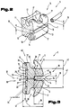
- FIG. 2 such a tooth attachment 5 is shown on a larger scale, which is made of ceramic material 10.
- the one-piece base body 11 of the tooth attachment 5 has a holding part 12 and a guide part 13.
- the guide part 13 is provided with a longitudinal slot 14 and has projections 17 in the corner regions 15 of the same or projecting beyond the recesses 16 running parallel to the longitudinal slot 14.
- the longitudinal slot 14 has a preferably rectangular cross section, a width 18 running transversely to the longitudinal direction of the longitudinal slot 14 being slightly smaller than a diameter or a thickness 19 of the wire bracket 8 running parallel thereto.
- the holding part 12 is connected to the lingual or labial surface 9 of the tooth 3 via the adhesive layer 6.
- the choice of the surface 9 to which the tooth attachment 5 is attached depends on the regulation method used.
- the base body 11 is shown in section in an end view.
- a surface 20 of the holding part 12 is provided with inclined, curved or spatially shaped contact surfaces 21 in order to enable adaptation to the different surface shapes of the teeth 3.
- the bearing surface 21 is arranged on raised parts 22, which protrude a surface 23 of the base body 11 by a distance 24 in the direction of the tooth 3.
- the individual projecting parts 22 are distributed on the surface 23, as a result of which recesses 25 form between them, which serve to receive an adhesive 26 for connecting the tooth attachment 5 to the tooth 3.
- the adhesive 26 of the adhesive layer 6 is schematically indicated by dots in the sectional view.
- the tooth attachment 5 has only a small thickness 27 from the tooth 3 in the direction of the wire bracket 8, which is indicated here by dash-dotted lines in the recess 7 of the longitudinal slot 14.
- a depth 28 of the longitudinal slot 14 is formed such that, on the one hand, the material 10 of the base body 11 still has sufficient strength to transmit the regulatory forces from the wire bracket 8 to the tooth 3 and, on the other hand, does not result in an excessive distance between the wire bracket 8 and the surface 9 of the tooth 3 .
- the depth 28 of the longitudinal slot 14 extends from a front side 29 of the tooth attachment 5 in the direction of a tooth side 30.
- the radius 33 is preferably slightly smaller than half the diameter of the wire bracket 8 forming the thickness 19.
- the guide part 13 of the tooth attachment 5 On both sides of the plane of symmetry 32, the guide part 13 of the tooth attachment 5 has the extensions 17 already described above. Between the extensions 17 on the front side 29 and a web 37 of the holding part 12 on the tooth side 30, a receptacle 38 is provided parallel to the longitudinal slot 14 for holding a fixing element 39 - which is shown schematically in broken lines.
- the receptacles 38 for the fixing element 39 extend both from an upper side 40 and from an underside 41 of the tooth attachment 5 in the direction of the plane of symmetry 32 up to a thickness 42 of the base body 11. Starting from the thickness 42, the extensions 17 protrude beyond the receptacles 38 a height 43 which must be designed so that the fixing element 39 is held securely.
- the fixing element 39 is inserted along the receptacles 38 and spanning the wire bracket 8 in the direction of the plane of symmetry 32 from the front side 29 arranged.
- the wire bracket 8 is held in a secured position in the longitudinal slot 14.
- the tooth attachment 5 is shown in different views.
- the tooth attachment 5 has a length 44 and a height 45 in the direction of the plane of symmetry 32, which extends approximately at right angles to the plane of symmetry 32.
- the raised parts 22 arranged on the tooth side 30 of the tooth attachment 5 with their bearing surfaces 21 have an approximately V-shaped cross section with lengths 46, 47, side edges 48 being offset by an angle of approximately 45 ° with respect to the plane of symmetry 32 are.
- the contact surfaces 21 of the raised parts 22 are spatially shaped.
- the side edges 48 of the individual raised parts 22 are spaced apart from one another by distances 49.50 and thus form surfaces 51.52 in a V-grid arrangement.
- the depressions 25 necessary on the tooth side 30 of the tooth attachment 5 are formed between the surfaces 51, 52 for receiving the adhesive 26.
- tooth attachment 5 is shown cut in the plane of symmetry 32.
- the formation of the spatially curved support surfaces 21 on the raised parts 22 on the tooth side 30 can be seen particularly well.
- the support surfaces 21 are pivoted by angles 53, 54 to a reference plane running parallel to the base surface 31.
- the base area 31 of the longitudinal slot 14 is formed in a straight line over the length 44 of the tooth attachment 5.
- the base area 31 in the form of a circular arc section, elliptical section or another curve shape, as is schematically indicated here with dash-dotted lines. This is due to the interaction of the wire bracket 8 with the longitudinal slot 14 as well as the desired application of the tooth regulating device 4 dependent.
- FIG. 7 shows an embodiment variant of the tooth attachment 5 in which the tooth attachment 5 is made in several parts.
- the holding part 12 is preferably made of plastic and the guide part 13 is preferably made of ceramic material.
- a connecting area 55 between the holding part 12 and the guide part 13 is designed in the manner of a tongue and groove connection 56, a groove 57 in the holding part 12 having a width 58 and a depth 59.
- the holding part 12 can e.g. be produced by means of an extrusion process, injection molding process or the like, the tooth side 30 possibly being given the appropriate shape in a separate subsequent machining process and then being joined to form a unit by means of an adhesive layer 60 with the finished ceramic guide part 13, which forms an attachment body 61 .
- the connection between the holding part 12 and the attachment body 61 can e.g. also done by a welding process or also form-fitting.
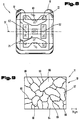
- the raised parts 22 have an approximately V-shaped or rectangular arrangement.
- the arrangement of the raised parts 22 on the tooth side 30 of the tooth attachment 5 forms support surfaces 62, 63, between which the depressions 25 for receiving the adhesive 26 are arranged.
- the material 10 is composed of the individual grains 64 to 67, with precipitations 69 forming at grain boundaries 68, which differ from the grains 64 to 67 by their visibility under X-rays.
- the base body 11 in the tooth attachment 5 described consists of ceramic material.
- the production of the base body 11 or of the holding or attachment part from ceramic material can be carried out in accordance with the methods known from the prior art, as described, inter alia, in US Pat. Nos. 3,026,210, 3,026,177, 4,150,317 and 4,954,080 are described.
- the tooth attachments 5, which are made of ceramic material, are usually produced from a high-purity aluminum oxide powder, a binder, additional materials to reduce grain growth, and X-ray-opaque oxides.
- the mass obtained in this way is deformed into the desired shape for a green body.
- the dry powder is pressed in a mold cavity using a powder compacting press.
- Another preferred method is to extrude the ceramic base material into the desired shape, and a final, mechanical shaping can take place before or after the sintering process.
- the green body is then prebaked with the addition of oxygen-enriched air at 1200 degrees Celsius for about 1 hour, so that the green body has sufficient strength for machining or for transfer to the sintering process.
- the green body can be sintered to the desired density, for example, under a reducing atmosphere, such as hydrogen, at temperatures between 1,750 and 1,950 degrees C.
- the time for the sintering can be between 45 min. and a few hours to achieve an average grain size between 5 and 40 microns and a desired light transmission.
- a slice of the finished body 11 with a thickness of 0.5 mm should have a light transmittance in visible light with a wavelength of 0.3 to 0.8 microns of 5 to 45%.
- hot isostatic pressing takes place, during which a pressure of approximately 30,000 psi is applied for a certain time at a temperature between 1450 and 1580 degrees C. in order to lower the pore content in the base body 11 V p below 0.003.
- a magnesium oxide in the content of less than 0.1% by weight is added to the aforementioned aluminum powder in order to prevent the formation of a magnesium-aluminum spinel phase (Mg Al2O4) and at the same time excessive grain growth.
- Mg Al2O4 magnesium-aluminum spinel phase
- a magnesium fluoride is also preferably added to the aforementioned mixture.
- This magnesium fluoride also limits grain growth in the early phase of the sintering process and is then excreted by evaporation during the late phase of the firing process.
- the desired x-ray opaque formation of the base body 11 is achieved by admixing an amount of 3 to 150 ppm ytterbium fluoride with a degree of purity greater than 99% and a particle size distribution below 7 micrometers, as well as 60 to 120 ppm of highly pure yttrium oxide and 3 to 30 ppm high purity lanthanum oxide reached. It is also possible to use a small amount of a suitable organic binder in order to give this entire mixture sufficient strength in the green phase.
- the starting materials for the production of the base body 11 can be a metal oxide, such as Chromium oxide, can be added to achieve the desired appearance.
- a metal oxide such as Chromium oxide
- the different shades of color of the teeth 3 of the wearer of such a tooth regulating device 4 can thus be taken into account.
Landscapes
- Health & Medical Sciences (AREA)
- Oral & Maxillofacial Surgery (AREA)
- Dentistry (AREA)
- Epidemiology (AREA)
- Life Sciences & Earth Sciences (AREA)
- Animal Behavior & Ethology (AREA)
- General Health & Medical Sciences (AREA)
- Public Health (AREA)
- Veterinary Medicine (AREA)
- Dental Tools And Instruments Or Auxiliary Dental Instruments (AREA)
- Apparatus For Radiation Diagnosis (AREA)
- Compositions Of Oxide Ceramics (AREA)
Claims (18)
- Dispositif régulateur des dents (4) avec des bagues dentaires céramiques (5) en une structure céramique polycristalline et divers agrégats avec une transparence optique pour la lumière visible pour une épaisseur de 0,5 mm comprise entre 5 et 60%, caractérisé en ce que sont disposées aux périphéries des grains (68) entre les grains polycristallins (64 à 67) des dépôts (69) visibles aux rayons X, les grains (64 à 67) d'un corps de base (11) pouvant être constitués d'une Zircone de grande pureté ou, comme cela est connu en soi, d'un oxyde d'aluminium et de différents agrégats, et en ce que les dépôts (69) visibles aux rayons X sont constitués par addition de 3 à 150 ppm de fluorure de ytterbium.
- Dispositif régulateur des dents selon la revendication 1, caractérisé en ce qu'on ajoute à l'oxyde d'aluminium des bagues dentaires (5) 60 à 120 ppm d'oxyde d'yttrium de grande pureté et/ou 3 à 30 ppm d'oxyde de lanthane de grande pureté.
- Dispositif régulateur des dents selon la revendication 1 ou 2, caractérisé en ce que les bagues dentaires cuites (5) ont une grandeur de grain moyenne de 5 à 90 micromètres.
- Dispositif régulateur des dents selon l'une ou plusieurs des revendications 1 à 3, caractérisé en ce que le volume moyen des pores Vp est inférieur à 0,003.
- Dispositif régulateur des dents selon une ou plusieurs des revendications 1 à 4, caractérisé en ce qu'un agrégat pour la croissance des grains contient moins que 0,1% en poids d'oxyde de magnésium de grande pureté et/ou 0,01 à 0,5% en poids de fluorure de magnésium.
- Dispositif régulateur des dents selon l'une ou plusieurs des revendications 1 à 5, caractérisé en ce qu'on ajoute à la matière céramique des bagues dentaires (5) 5 ppm à 15 ppm de fluorure de lithium.
- Dispositif régulateur des dents selon l'une ou plusieurs des revendications 1 à 6, caractérisé en ce que la structure de base est constituée d'un oxyde d'yttrium de grande pureté.
- Dispositif régulateur des dents selon l'une ou plusieurs des revendications 1 à 7, caractérisé en ce que la structure de base est constituée d'un mélange de titano-zirconate de plomb modifié avec 3 à 150 ppm de lanthane, de fluorure d'ytterbium et de 3 à 30 ppm d'oxyde d'yttrium.
- Dispositif régulateur des dents selon l'une ou plusieurs des revendications 1 à 8, caractérisé en ce que la structure de base est constituée d'une céramique de zircone stabilisée avec un polycristallin de Al₂O₃ et des agrégats constitués par le fluorure d'ytterbium et le lanthane.
- Dispositif régulateur des dents selon l'une ou plusieurs des revendications 1 à 9, caractérisé en ce que les grains polycristallins (64 à 67), avec leur dépôt (69) visible aux rayons X aux périphéries des grains (68) constituent le corps de base (11) et/ou un corps rapporté (61) d'une bague dentaire (5) constituée au moins de deux parties.
- Dispositif régulateur des dents selon l'une ou plusieurs des revendications 1 à 10, caractérisé en ce que le corps de base (11) ou le corps rapporté (61) de la bague dentaire (5) est réalisé en matière synthétique.
- Dispositif régulateur des dents selon l'une ou plusieurs des revendications 1 à 11, caractérisé en ce que le corps de base ou rapporté (11, 61) constitué des grains polycristallins (64 à 67) avec les dépôts (69) visibles aux rayons X aux périphéries (68) des grains est noyés dans ou reliés par concordance des formes à un corps rapporté ou de base (61, 11) constitué d'un autre matériau.
- Dispositif régulateur des dents selon l'une ou plusieurs des revendications 1 à 12, caractérisé en ce que le corps de base (11) présente des surfaces d'appui (21, 62, 63) ou surfaces (51, 52) courbées spatialement qui sont préparées de préférence pour une liaison chimique ou mécanique.
- Dispositif régulateur des dents selon l'une ou plusieurs des revendications 1 à 13, caractérisé en ce qu'une surface (20) recevant une colle (26) présente des parties surélevées (22) disposées entre des creux (25).
- Dispositif régulateur des dents selon l'une ou plusieurs des revendications 1 à 14, caractérisé en ce que le corps rapporté (61) présente des évidements courbés, des fentes, des ailes et/ou des crochets.
- Dispositif régulateur des dents selon l'une ou plusieurs des revendications 1 à 15, caractérisé en ce que la surface de la bague dentaire (5) constituée de corps polycristallins (64 à 67) est polie chimiquement et/ou mécaniquement.
- Dispositif régulateur des dents selon l'une ou plusieurs des revendications 1 à 16, caractérisé en ce que le corps de base céramique (11) présente une translucidité colorée.
- Dispositif régulateur des dents selon l'une ou plusieurs des revendications 1 à 17, caractérisé en ce que le corps de base céramique (11) est mélangé avec un oxyde métallique pour la coloration, par exemple avec un oxyde de chrome.
Applications Claiming Priority (3)
| Application Number | Priority Date | Filing Date | Title |
|---|---|---|---|
| AT0136591A AT401227B (de) | 1991-07-09 | 1991-07-09 | Zahnregulierungsvorrichtung mit einem keramischen zahnaufsatz |
| AT1365/91 | 1991-07-09 | ||
| PCT/AT1992/000088 WO1993000865A1 (fr) | 1991-07-09 | 1992-07-09 | Dispositif orthodontique avec fixation dentaire en ceramique |
Publications (2)
| Publication Number | Publication Date |
|---|---|
| EP0593611A1 EP0593611A1 (fr) | 1994-04-27 |
| EP0593611B1 true EP0593611B1 (fr) | 1996-06-12 |
Family
ID=3512306
Family Applications (1)
| Application Number | Title | Priority Date | Filing Date |
|---|---|---|---|
| EP92914956A Expired - Lifetime EP0593611B1 (fr) | 1991-07-09 | 1992-07-09 | Dispositif orthodontique avec fixation dentaire en ceramique |
Country Status (6)
| Country | Link |
|---|---|
| US (1) | US5441408A (fr) |
| EP (1) | EP0593611B1 (fr) |
| AT (2) | AT401227B (fr) |
| AU (1) | AU2272292A (fr) |
| DE (1) | DE59206577D1 (fr) |
| WO (1) | WO1993000865A1 (fr) |
Cited By (2)
| Publication number | Priority date | Publication date | Assignee | Title |
|---|---|---|---|---|
| WO2001041670A1 (fr) | 1999-12-07 | 2001-06-14 | Inocermic Gesellschaft für innovative Keramik mbH | Procede de fabrication d"une prothese dentaire ceramique, et prothese dentaire ceramique haute resistance ainsi obtenue |
| WO2010132915A2 (fr) | 2009-05-20 | 2010-11-25 | Pbd, Patent & Business Development Ag | Composant orthodontique céramique polycristallin |
Families Citing this family (38)
| Publication number | Priority date | Publication date | Assignee | Title |
|---|---|---|---|---|
| DE4434209A1 (de) * | 1994-09-24 | 1996-03-28 | Foerster Rolf | Vorrichtung zum Regulieren der Zahnstellung |
| US5681165A (en) * | 1995-05-09 | 1997-10-28 | Feldman; Randy Mark | Ceramic orthodontic bracket and method of manufacturing |
| US5746594A (en) * | 1996-03-05 | 1998-05-05 | Minnesota Mining & Manufacturing Co. | Orthodontic appliance with asymmetric bonding structure |
| RU2157431C2 (ru) * | 1997-07-25 | 2000-10-10 | Борик Михаил Александрович | Способ получения высокопрочного материала (варианты), устройства на основе этого материала и способ их изготовления |
| US6878456B2 (en) | 2001-12-28 | 2005-04-12 | 3M Innovative Properties Co. | Polycrystalline translucent alumina-based ceramic material, uses, and methods |
| US6648638B2 (en) | 2001-12-28 | 2003-11-18 | 3M Innovative Properties Company | Orthodontic appliances including polycrystalline alumina-based ceramic material, kits, and methods |
| US20040072119A1 (en) * | 2002-06-21 | 2004-04-15 | Orthoarm, Inc. | Self-ligating orthodontic bracket |
| US6685468B1 (en) * | 2002-08-21 | 2004-02-03 | Tp Orthodontics, Inc. | Bondable orthodontic appliance with a polymer resin bonding base |
| US7959437B2 (en) | 2002-10-29 | 2011-06-14 | Rmo, Inc. | Orthodontic appliance with encoded information formed in the base |
| US7695277B1 (en) | 2004-10-28 | 2010-04-13 | Rmo, Inc. | Orthodontic bracket with frangible cover mechanism |
| US7140875B2 (en) * | 2004-02-03 | 2006-11-28 | 3M Innovative Properties Company | Orthodontic bracket with reinforced tiewings |
| US7094052B2 (en) * | 2004-04-30 | 2006-08-22 | Norbert Abels | Orthodontic brackets with temporarily visible marking features |
| US7913002B2 (en) * | 2004-08-20 | 2011-03-22 | Advantest Corporation | Test apparatus, configuration method, and device interface |
| US7134872B2 (en) * | 2004-09-02 | 2006-11-14 | Norbert Abels | Colored orthodontic brackets |
| US7611352B2 (en) * | 2006-08-31 | 2009-11-03 | Ultradent Products, Inc. | Lifestyle bracket system having interchangeable ligation covers |
| US9554875B2 (en) | 2006-09-07 | 2017-01-31 | Rmo, Inc. | Method for producing a customized orthodontic appliance |
| US8376739B2 (en) | 2011-05-12 | 2013-02-19 | Rmo, Inc. | Self ligating orthodontic bracket having a rotatable member |
| WO2008031060A2 (fr) | 2006-09-07 | 2008-03-13 | Rmo, Inc. | Tube buccal à frottement réduit et procédé d'utilisation |
| US8979528B2 (en) | 2006-09-07 | 2015-03-17 | Rmo, Inc. | Customized orthodontic appliance method and system |
| US20090115084A1 (en) * | 2007-11-05 | 2009-05-07 | James R. Glidewell Dental Ceramics, Inc. | Slip-casting method of fabricating zirconia blanks for milling into dental appliances |
| JP5770630B2 (ja) | 2008-08-13 | 2015-08-26 | オルムコ コーポレイション | 審美的歯列矯正ブラケット及びその製造方法 |
| AU2009238317B2 (en) | 2008-11-14 | 2011-10-06 | Ormco Corporation | Surface treated polycrystalline ceramic orthodontic bracket and method of making same |
| RU2422412C2 (ru) * | 2008-12-16 | 2011-06-27 | Учреждение Российской академии наук Институт физики прочности и материаловедения СО РАН (ИФПМ СО РАН) | Способ повышения износостойкости поверхности спеченного керамического изделия |
| WO2010107567A1 (fr) | 2009-03-16 | 2010-09-23 | Rmo, Inc. | Bracket orthodontique doté d'un canal de fil métallique pour arc, et mécanisme de retenue de fil métallique pour arc |
| US11219507B2 (en) | 2009-03-16 | 2022-01-11 | Orthoamerica Holdings, Llc | Customized orthodontic appliance and method |
| US8867800B2 (en) | 2009-05-27 | 2014-10-21 | James R. Glidewell Dental Ceramics, Inc. | Method of designing and fabricating patient-specific restorations from intra-oral scanning of a digital impression |
| US11382722B2 (en) * | 2011-03-17 | 2022-07-12 | Cameron Mashouf | Orthodontic brackets for deciduous teeth |
| US10433933B2 (en) | 2011-03-17 | 2019-10-08 | Cameron Mashouf | Orthodontic bracket for use on deciduous teeth |
| USD660436S1 (en) | 2011-05-13 | 2012-05-22 | Rmo, Inc. | Orthodontic bracket |
| USD660435S1 (en) | 2011-05-13 | 2012-05-22 | Rmo, Inc. | Orthodontic bracket |
| USD660968S1 (en) | 2011-05-13 | 2012-05-29 | Rmo, Inc. | Orthodontic bracket |
| USD847349S1 (en) | 2011-09-22 | 2019-04-30 | Rmo, Inc. | Orthodontic lock with flange |
| WO2013068456A1 (fr) * | 2011-11-08 | 2013-05-16 | Orthodontic Research And Development, S.L. | Support pour appareil orthodontique |
| US9434651B2 (en) | 2012-05-26 | 2016-09-06 | James R. Glidewell Dental Ceramics, Inc. | Method of fabricating high light transmission zirconia blanks for milling into natural appearance dental appliances |
| USD726318S1 (en) | 2013-01-17 | 2015-04-07 | Rmo, Inc. | Dental instrument for a self-ligating orthodontic clip |
| USD721811S1 (en) | 2013-10-29 | 2015-01-27 | Rmo, Inc. | Orthodontic bracket |
| CN104721060A (zh) * | 2015-03-31 | 2015-06-24 | 苏州维泰生物技术有限公司 | 一种用于人体器官制备的陶瓷材料及其制备方法 |
| US11731312B2 (en) | 2020-01-29 | 2023-08-22 | James R. Glidewell Dental Ceramics, Inc. | Casting apparatus, cast zirconia ceramic bodies and methods for making the same |
Citations (1)
| Publication number | Priority date | Publication date | Assignee | Title |
|---|---|---|---|---|
| US4954080A (en) * | 1986-05-08 | 1990-09-04 | Unitek Corporation | Ceramic orthodontic appliance |
Family Cites Families (14)
| Publication number | Priority date | Publication date | Assignee | Title |
|---|---|---|---|---|
| US1976141A (en) * | 1932-06-01 | 1934-10-09 | Charles Edward Boyd | Method of producing orthodontic band brackets |
| US2045025A (en) * | 1934-08-17 | 1936-06-23 | Charles Edward Boyd | Method of producing orthodontic band brackets |
| US3971754A (en) * | 1973-12-10 | 1976-07-27 | Pennwalt Corporation | X-ray opaque, enamel-matching dental filling composition |
| US4302532A (en) * | 1976-06-23 | 1981-11-24 | Melvin Wallshein | Orthodontic bracket with protective insert or liner |
| US4322206A (en) * | 1978-08-03 | 1982-03-30 | Zulauf Inc. | Orthodontic appliance |
| DE2935810A1 (de) * | 1979-09-05 | 1981-04-02 | Colgate-Palmolive Co., 10022 New York, N.Y. | Fuer roentgenstrahlen undurchlaessige zahnfuellmassen |
| US4430061A (en) * | 1980-11-03 | 1984-02-07 | Johnson And Johnson | Orthodontic bracket assembly |
| FR2559059B1 (fr) * | 1984-02-07 | 1988-12-23 | Fantino Jean | Composition d'un materiau pour application dentaire et procede de realisation d'appareil dentaire a partir de celle-ci |
| DE3588089T2 (de) * | 1984-04-23 | 1996-10-02 | Company Orthodontics A | Orthodontisches Bracket aus kristallinem Aluminiumoxid |
| DE3502594A1 (de) * | 1985-01-26 | 1986-07-31 | Etablissement Dentaire Ivoclar, Schaan | Roentgenopaker dentalwerkstoff |
| US4604057A (en) * | 1985-07-03 | 1986-08-05 | American Orthodontics Corporation | Cast orthodontic appliance |
| FR2627377B1 (fr) * | 1988-02-19 | 1990-07-27 | Sadoun Michael | Dispositif de fixation d'arc en orthodontie |
| US4948538A (en) * | 1988-10-11 | 1990-08-14 | Gte Laboratories Incorporated | Method of making translucent alumina articles |
| US4988293A (en) * | 1988-11-07 | 1991-01-29 | Union Carbide Chemicals And Plastics Company Inc. | Toughness coating for crystalline orthodontic brackets |
-
1991
- 1991-07-09 AT AT0136591A patent/AT401227B/de not_active IP Right Cessation
-
1992
- 1992-07-09 DE DE59206577T patent/DE59206577D1/de not_active Expired - Lifetime
- 1992-07-09 AT AT92914956T patent/ATE139106T1/de not_active IP Right Cessation
- 1992-07-09 AU AU22722/92A patent/AU2272292A/en not_active Abandoned
- 1992-07-09 WO PCT/AT1992/000088 patent/WO1993000865A1/fr not_active Ceased
- 1992-07-09 EP EP92914956A patent/EP0593611B1/fr not_active Expired - Lifetime
- 1992-07-09 US US08/178,267 patent/US5441408A/en not_active Expired - Lifetime
Patent Citations (1)
| Publication number | Priority date | Publication date | Assignee | Title |
|---|---|---|---|---|
| US4954080A (en) * | 1986-05-08 | 1990-09-04 | Unitek Corporation | Ceramic orthodontic appliance |
Cited By (2)
| Publication number | Priority date | Publication date | Assignee | Title |
|---|---|---|---|---|
| WO2001041670A1 (fr) | 1999-12-07 | 2001-06-14 | Inocermic Gesellschaft für innovative Keramik mbH | Procede de fabrication d"une prothese dentaire ceramique, et prothese dentaire ceramique haute resistance ainsi obtenue |
| WO2010132915A2 (fr) | 2009-05-20 | 2010-11-25 | Pbd, Patent & Business Development Ag | Composant orthodontique céramique polycristallin |
Also Published As
| Publication number | Publication date |
|---|---|
| AT401227B (de) | 1996-07-25 |
| WO1993000865A1 (fr) | 1993-01-21 |
| AU2272292A (en) | 1993-02-11 |
| US5441408A (en) | 1995-08-15 |
| ATE139106T1 (de) | 1996-06-15 |
| ATA136591A (de) | 1995-12-15 |
| DE59206577D1 (de) | 1996-07-18 |
| EP0593611A1 (fr) | 1994-04-27 |
Similar Documents
| Publication | Publication Date | Title |
|---|---|---|
| EP0593611B1 (fr) | Dispositif orthodontique avec fixation dentaire en ceramique | |
| DE69004306T2 (de) | Künstliche Kronen- und Zahnersatzteile. | |
| DE68919340T2 (de) | Künstliche Zahnkrone. | |
| DE102007011339A1 (de) | Blockkörper | |
| EP2926760B1 (fr) | Corps de facette avant de dent | |
| EP3829482B1 (fr) | Ébauche multicolore à des fins dentaires | |
| EP2819613B1 (fr) | Ébauche pour la fabrication d'une prothèse dentaire | |
| DE3435348C2 (de) | Künstliche Zahnkrone und Verfahren zu ihrer Herstellung | |
| DE102015122864A1 (de) | Verfahren zur Herstellung eines Rohlings sowie dentale Restauration | |
| DE2639887A1 (de) | Enossales dental-halbimplantat | |
| EP0807422A1 (fr) | Procédé pour la production de reconstructions dentaires et ébauche pour la mise en oeuvre du procédé | |
| WO2018115529A1 (fr) | Corps multicouche en céramique oxydée présentant un comportement au frittage adapté | |
| DE102016106370A1 (de) | Verfahren zur Herstellung eines eingefärbten Rohlings sowie Rohling | |
| DE102015122861A1 (de) | Verfahren zur Herstellung eines Rohlings, Rohling sowie eine dentale Restauration | |
| EP0416637A1 (fr) | Assortiment pour choisir une couleur dentaire | |
| EP2034947A1 (fr) | Matériau et ébauche pour prothèses dentaires | |
| DE3855703T2 (de) | Verfahren zur herstellung eines keramischen orthodontischen brackets | |
| EP4197486B1 (fr) | Blanc et procédé de préparation d'un tel | |
| DE3620542A1 (de) | Vorgefertigter keramik-formkoerper | |
| WO2010132915A2 (fr) | Composant orthodontique céramique polycristallin | |
| DE4120132C2 (de) | Zahnersatz | |
| EP1782748A1 (fr) | Appareil de traitement | |
| CH656064A5 (en) | Profile for stabilising and connecting natural teeth to one another | |
| EP4431481A1 (fr) | Céramique à base d'oxydes avec pigment | |
| EP0643951B1 (fr) | Dispositif pour la production d'échantillons frittés produisant la colorisation pour prothèses dentaires |
Legal Events
| Date | Code | Title | Description |
|---|---|---|---|
| PUAI | Public reference made under article 153(3) epc to a published international application that has entered the european phase |
Free format text: ORIGINAL CODE: 0009012 |
|
| 17P | Request for examination filed |
Effective date: 19931227 |
|
| AK | Designated contracting states |
Kind code of ref document: A1 Designated state(s): AT BE CH DE DK ES FR GB GR IT LI LU MC NL SE |
|
| 17Q | First examination report despatched |
Effective date: 19951114 |
|
| GRAH | Despatch of communication of intention to grant a patent |
Free format text: ORIGINAL CODE: EPIDOS IGRA |
|
| GRAA | (expected) grant |
Free format text: ORIGINAL CODE: 0009210 |
|
| AK | Designated contracting states |
Kind code of ref document: B1 Designated state(s): AT BE CH DE DK ES FR GB GR IT LI LU MC NL SE |
|
| PG25 | Lapsed in a contracting state [announced via postgrant information from national office to epo] |
Ref country code: NL Free format text: LAPSE BECAUSE OF FAILURE TO SUBMIT A TRANSLATION OF THE DESCRIPTION OR TO PAY THE FEE WITHIN THE PRESCRIBED TIME-LIMIT Effective date: 19960612 Ref country code: IT Free format text: LAPSE BECAUSE OF FAILURE TO SUBMIT A TRANSLATION OF THE DESCRIPTION OR TO PAY THE FEE WITHIN THE PRESCRIBED TIME-LIMIT;WARNING: LAPSES OF ITALIAN PATENTS WITH EFFECTIVE DATE BEFORE 2007 MAY HAVE OCCURRED AT ANY TIME BEFORE 2007. THE CORRECT EFFECTIVE DATE MAY BE DIFFERENT FROM THE ONE RECORDED. Effective date: 19960612 Ref country code: GR Free format text: LAPSE BECAUSE OF FAILURE TO SUBMIT A TRANSLATION OF THE DESCRIPTION OR TO PAY THE FEE WITHIN THE PRESCRIBED TIME-LIMIT Effective date: 19960612 Ref country code: GB Effective date: 19960612 Ref country code: FR Effective date: 19960612 Ref country code: ES Free format text: THE PATENT HAS BEEN ANNULLED BY A DECISION OF A NATIONAL AUTHORITY Effective date: 19960612 Ref country code: DK Effective date: 19960612 |
|
| REF | Corresponds to: |
Ref document number: 139106 Country of ref document: AT Date of ref document: 19960615 Kind code of ref document: T |
|
| PG25 | Lapsed in a contracting state [announced via postgrant information from national office to epo] |
Ref country code: AT Effective date: 19960709 |
|
| REF | Corresponds to: |
Ref document number: 59206577 Country of ref document: DE Date of ref document: 19960718 |
|
| PG25 | Lapsed in a contracting state [announced via postgrant information from national office to epo] |
Ref country code: LU Free format text: LAPSE BECAUSE OF NON-PAYMENT OF DUE FEES Effective date: 19960731 Ref country code: BE Effective date: 19960731 |
|
| REG | Reference to a national code |
Ref country code: CH Ref legal event code: PUE Owner name: HIRSCH ADVANCED CERAMICS GESELLSCHAFT M.B.H. -DANN |
|
| RAP2 | Party data changed (patent owner data changed or rights of a patent transferred) |
Owner name: CDB CORPORATION |
|
| REG | Reference to a national code |
Ref country code: CH Ref legal event code: NV Representative=s name: ABP PATENTMARKETING GMBH |
|
| PG25 | Lapsed in a contracting state [announced via postgrant information from national office to epo] |
Ref country code: SE Effective date: 19960912 |
|
| NLT2 | Nl: modifications (of names), taken from the european patent patent bulletin |
Owner name: CDB CORPORATION |
|
| NLV1 | Nl: lapsed or annulled due to failure to fulfill the requirements of art. 29p and 29m of the patents act | ||
| EN | Fr: translation not filed | ||
| GBV | Gb: ep patent (uk) treated as always having been void in accordance with gb section 77(7)/1977 [no translation filed] |
Effective date: 19960612 |
|
| PG25 | Lapsed in a contracting state [announced via postgrant information from national office to epo] |
Ref country code: MC Effective date: 19970131 |
|
| PLBE | No opposition filed within time limit |
Free format text: ORIGINAL CODE: 0009261 |
|
| STAA | Information on the status of an ep patent application or granted ep patent |
Free format text: STATUS: NO OPPOSITION FILED WITHIN TIME LIMIT |
|
| 26N | No opposition filed | ||
| REG | Reference to a national code |
Ref country code: CH Ref legal event code: PUE Owner name: HIRSCH SCHWEIZ AG Free format text: CDB CORPORATION#3625 HIGHWAY 421#NORTH WILMINGTON/NC 28401 (US) -TRANSFER TO- HIRSCH SCHWEIZ AG#NIDAUGASSE 15#2502 BIEL (CH) Ref country code: CH Ref legal event code: PUE Owner name: PBD, PATENT & BUSINESS DEVELOPMENT AG Free format text: HAT SKYLINE GMBH#HIRSCHSTRASSE 5#9020 KLAGENFURT (AT) -TRANSFER TO- PBD, PATENT & BUSINESS DEVELOPMENT AG#GOTTHARDSTRASSE 20#6304 ZUG (CH) Ref country code: CH Ref legal event code: PUE Owner name: HAT SKYLINE GMBH Free format text: HIRSCH SCHWEIZ AG#NIDAUGASSE 15#2502 BIEL (CH) -TRANSFER TO- HAT SKYLINE GMBH#HIRSCHSTRASSE 5#9020 KLAGENFURT (AT) |
|
| PGFP | Annual fee paid to national office [announced via postgrant information from national office to epo] |
Ref country code: CH Payment date: 20100721 Year of fee payment: 19 |
|
| REG | Reference to a national code |
Ref country code: CH Ref legal event code: NV Representative=s name: ABP PATENT NETWORK SWISS GMBH |
|
| PGFP | Annual fee paid to national office [announced via postgrant information from national office to epo] |
Ref country code: DE Payment date: 20110729 Year of fee payment: 20 |
|
| REG | Reference to a national code |
Ref country code: CH Ref legal event code: PL |
|
| PG25 | Lapsed in a contracting state [announced via postgrant information from national office to epo] |
Ref country code: CH Free format text: LAPSE BECAUSE OF NON-PAYMENT OF DUE FEES Effective date: 20110731 Ref country code: LI Free format text: LAPSE BECAUSE OF NON-PAYMENT OF DUE FEES Effective date: 20110731 |
|
| REG | Reference to a national code |
Ref country code: DE Ref legal event code: R071 Ref document number: 59206577 Country of ref document: DE |
|
| REG | Reference to a national code |
Ref country code: DE Ref legal event code: R071 Ref document number: 59206577 Country of ref document: DE |
|
| PG25 | Lapsed in a contracting state [announced via postgrant information from national office to epo] |
Ref country code: DE Free format text: LAPSE BECAUSE OF EXPIRATION OF PROTECTION Effective date: 20120710 |