EP0593669B1 - Sidecar de bicyclette - Google Patents
Sidecar de bicyclette Download PDFInfo
- Publication number
- EP0593669B1 EP0593669B1 EP92916295A EP92916295A EP0593669B1 EP 0593669 B1 EP0593669 B1 EP 0593669B1 EP 92916295 A EP92916295 A EP 92916295A EP 92916295 A EP92916295 A EP 92916295A EP 0593669 B1 EP0593669 B1 EP 0593669B1
- Authority
- EP
- European Patent Office
- Prior art keywords
- sidecar
- bicycle
- assembly
- mounting
- connecting means
- Prior art date
- Legal status (The legal status is an assumption and is not a legal conclusion. Google has not performed a legal analysis and makes no representation as to the accuracy of the status listed.)
- Expired - Lifetime
Links
Images



Classifications
-
- B—PERFORMING OPERATIONS; TRANSPORTING
- B62—LAND VEHICLES FOR TRAVELLING OTHERWISE THAN ON RAILS
- B62K—CYCLES; CYCLE FRAMES; CYCLE STEERING DEVICES; RIDER-OPERATED TERMINAL CONTROLS SPECIALLY ADAPTED FOR CYCLES; CYCLE AXLE SUSPENSIONS; CYCLE SIDECARS, FORECARS, OR THE LIKE
- B62K27/00—Sidecars; Forecars; Trailers or the like specially adapted to be attached to cycles
- B62K27/10—Other component parts or accessories
- B62K27/12—Coupling parts for attaching cars or the like to cycle; Arrangements thereof
-
- B—PERFORMING OPERATIONS; TRANSPORTING
- B62—LAND VEHICLES FOR TRAVELLING OTHERWISE THAN ON RAILS
- B62K—CYCLES; CYCLE FRAMES; CYCLE STEERING DEVICES; RIDER-OPERATED TERMINAL CONTROLS SPECIALLY ADAPTED FOR CYCLES; CYCLE AXLE SUSPENSIONS; CYCLE SIDECARS, FORECARS, OR THE LIKE
- B62K27/00—Sidecars; Forecars; Trailers or the like specially adapted to be attached to cycles
Definitions
- This invention relates generally to sidecar-type vehicles and more particularly concerns a sidecar which is particularly adapted for use with bicycles, as set out in the first part of claim 1 and shown in GB-A-9551.
- the present invention is a sidecar for a bicycle, which includes a sidecar assembly, including a portion thereof which is adapted to support a passenger, wherein the sidecar assembly includes a wheel positioned within the assembly such that the passenger is positioned substantially directly above the wheel; first connecting means extending between the sidecar assembly to the bicycle at points in the vicinity of the axles of the respective wheels; and second connecting means extending between the sidecar assembly and the bicycle at points located a distance above the first connecting means, wherein the first and second connecting means each have swivel connections between the sidecar assembly and the bicycle, such that the sidecar moves in approximately mirror fashion to movement of the bicycle, as defined in claim 1.
- Figure 1 is an isometric view of one embodiment of the combination of the sidecar of the present invention and a bicycle.
- Figure 2 is a side elevational view of the bicycle sidecar of Figure 1.
- Figure 3 is a front elevational view of the sidecar of Figures 1 and 2.
- Figure 4 is an isometric view of the first connecting assembly of the sidecar of Figure 1.
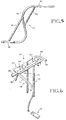
- Figure 5 is a top view of the second connecting assembly of the sidecar of Figure 1.
- Figure 6 is an isometric view of the bicycle mounting assembly.
- Figure 7 is an isometric view of the present invention showing a cover element in place on the sidecar assembly.
- Figures 1, 2 and 3 show generally one embodiment of the bicycle sidecar of the present invention.
- Figure 1 shows the sidecar relative to a conventional bicycle.
- the bicycle is shown generally at 10, and for purposes of illustration is a conventional adult-sized bicycle.
- the sidecar shown generally at 12 includes a frame assembly referred to generally at 14.
- the frame assembly includes a first frame element 16 in the form of an elongated loop of 25mm (one inch) aluminum tubing, the loop being approximately 1.2m (48 inches) long from end to end. All other portions of the frame 14 are in the embodiment shown likewise made from 25mm (one inch) aluminum tubing. Alternatively, 19mm (3/4 inch) thin-walled steel could be used.
- the rear end 18 of frame element 16 is blunt relative to the front end 20 thereof, which is curved.
- a lateral brace element 22 extends between opposite sides of frame element 16, near the rear end 18 thereof.
- a longitudinal brace extends from the rear end 18 of frame element 16 to the approximate center of lateral brace 22. All of the frame connections in this embodiment are accomplished by welding in the embodiment shown.
- a second frame element 26 comprises two elongated sections of tubing 28 and 30. Sections 28, 30 are generally separated by 89mm (31 ⁇ 2 inches) over their respective lengths but are joined to other frame elements at the rear and front ends 31 and 32, respectively. For instance, rear end 31 of second frame element 26 is joined to the rear end 18 of the first frame element 16.
- the second frame element 26 extends downwardly at an angle of approximately 60° from its point of connection with the rear end 18 of the first frame element for a length of approximately 560mm (22 inches), at which point it becomes basically horizontal, with a slight upward bend near the front end 32 thereof.
- a wheel 34 is mounted for rotation. In the embodiment shown, the wheel 34 is approximately 400mm (16 inches) in diameter.
- a third frame element is positioned above the first frame element and includes a tubular element 38 basically in the form of an elongated loop which is Positioned at an angle of approximately 30° to the first frame element 16.
- the rear end of the third frame element is blunt (it is joined to the rear end of first frame element 16) while the front end 39 is curved.
- a bracing element portion 40 of the third frame element extends from the rear end of the third frame element, which joins the rear ends of the first and second elements, curving slightly upwardly toward the front end thereof and then curving downwardly to join the remainder of the third frame element at the front end thereof. It should be noted in the particular embodiment shown that the rear ends of the respective first, second and third frame elements are approximately coincident, so that there is a substantially common joinder point.
- the third frame element basically provides a frame for an overhead cover for the passenger, while the second frame provides the basic support for the wheel.
- a fourth frame element 48 is basically in the form of a loop with one end open.
- the two free ends 49, 50 of the loop are connected to tubular element 38 of the third frame element at approximately the mid-point between the front and rear ends thereof.
- the loop element 48 extends from those points downwardly at an angle of about 45° from the vertical, connecting at its lower end to the front end 32 of the second frame element.
- the first, second, third, and fourth frame elements provide a stable unit, due to their relative arrangement and points of connection, where they are welded together.
- a horizontal member 53 extends from tubular element 38 to the fourth frame element 48, approximately 200mm (8 inches) or so above the first frame element, on the side of the sidecar adjacent the bicycle. The purpose of member 53 will be clarified in following paragraphs.
- a loop bracing member 54 (open at the top) extends from the opposite sides of fourth frame element 48 down to the second frame element at a point located at approximately one-third of the overall length of the second frame element from the front end 32 thereof.
- An additional bracing member 58 curves upwardly from the front end 32 of second frame element 26 to the front end 20 of the first frame element 16, providing a forward protection for the passenger, and also providing a shaping capability for a sidecar cover.
- the bracing members 54 and 58 also provide additional strength for the sidecar structure.
- a section of flexible cloth or plastic material 59 is connected via snaps or the like to the opposite sides of the fourth frame element 48.
- the material is configured and shaped so as to provide a convenient seat for the user.
- a platform 60 for the feet of the passenger may be positioned between the two sides of the second frame element 26 forward of loop bracing member 54.
- a canopy cover element can be provided across the top of the third frame element and also around the front of the sidecar extending around the forward portions of the first and third frame elements and extending downwardly from the third frame element, thereby providing a capability of completely enclosing the passenger.
- the various sections of the cover can be connected with zippers or the like.
- the complete cover is shown at 61 in Figure 10. A portion 63A of the complete cover 61 will be transparent, so the passenger can see out.
- the mounting assembly 62 includes a rack portion 63 which in the embodiment shown is in the form of a rectangle. Extending from the front end 64 of rack 63 are two prongs 66-66 which attach in conventional fashion to the frame of the bicycle underneath the bicycle seat 67. Two sets of forks 68-70 extend downwardly from the rack 63.
- the fork sets 68, 70 each include two elongated tubular elements.
- tubular element 71 extends from the midway point of the rack down to the axle of the rear wheel of the bicycle, where it is conventionally connected, while tubular element 72 extends downwardly and at an angle from the rear end of the rack, joining tubular element 71 a small distance above the axle.
- Fork set 70 also comprises two tubular elements 73, 74.
- Tubular element 73 is similar to element 71 for fork set 68 and connects conventionally with the axle of the rear wheel of the bicycle.
- Tubular element 74 extends from the rear of the rack down to element 73, where it is welded to element 73 but then curves somewhat rearwardly and downwardly as shown, terminating approximately 125mm (5 inches) below the axle of the bicycle wheel. This extended portion permits connection of the bicycle to the sidecar, as discussed in more detail below.
- a first connecting assembly shown generally at 76 extends between the second frame element 26 of the sidecar and the lower end of element 74 of fork set 70 on the bicycle.
- the connecting assembly is shown in detail in Figure 4, but also in Figures 1 and 3.
- the connecting assembly 76 includes an elongated tubular member 77A approximately 25mm (1 inch) in diameter, which extends directly (straight across) between tubular member 74 and the second frame element 26.
- An angle element 79A extends from member 77A to frame element 26 at a point to the rear of the connection point between member 77A and frame element 26.
- An additional short bracing member 81 extends between members 77A and 79A, giving a triangle effect for the connecting assembly 76.
- connection points between member 77A and 79A and tubular member 74 and second frame element 26, respectively, are swivel-type connections, providing a swiveling capability in the vertical plane of the bicycle and the sidecar, as the bicycle and the sidecar move in operation.
- the connecting assembly 76 is arranged so that the axle of the sidecar wheel 34 is approximately in the same vertical plane as the axle of the rear wheel of the bicycle.
- a second connecting assembly 77 extends between first frame element 16 and the mounting assembly 62 on the bicycle, in particular the rack portion 63 thereof.
- Connecting assembly 77 comprises a generally S-shaped piece 78 and two parallel brace pieces 79 and 80 which provide lateral bracing for the S-shaped piece 78.
- the S-shaped piece 78 has two end portions which are substantially straight (and parallel) for a short distance.
- One end portion 82 of S-shaped piece 78 fits into nylon mounting elements 84-84 which are positioned on rack 63.
- Mounting elements 84-84 extend downwardly from brackets on rack 63 and are configured relative to the S-shaped piece 78 so as to firmly retain the S-shaped piece but permit rotation of the S-shaped piece in a vertical plane.
- the other end portion 86 of the S-shaped piece 78 fits into similar nylon mounting brackets 88-88 mounted directly on brace 24 of the first frame element 16. Mounting brackets 88-88 hold the S-shaped piece 78 firmly but permit rotation therein.
- connecting assembly 77 is slightly longer than connecting assembly 76 508mm (20 inches) as opposed to 432mm (17 inches) so that the top leg of the parallelogram is slightly longer than the bottom leg.
- the vertical distance between the connecting assemblies 76 and 77 is approximately 508mm (20 inches). It would of course be possible to arrange the points of connection so that an exact parallelogram is achieved.
- a passenger is first situated in a seated position in the sidecar.
- the seat is cloth or other fabric which is configured and designed to accommodate a passenger while being secured to and by the fourth frame element 48 and the brace 54 extending down therefrom to the second frame element 26.
- the passenger may be completely enclosed with zippered or snap-button coverings which extend around the first frame element forward of the passenger, with a transparent portion in front of the passenger, as shown in Figure 7.
- the bicycle is ridden in conventional fashion.
- the sidecar due to its particular connective arrangement with the bicycle, including the position of the wheel on the sidecar relative to the rear wheel on the bicycle, follows the movement of the bicycle.
- the sidecar is configured so that the center-of-gravity of the passenger is directly over the sidecar wheel 34. This arrangement has been found to result in improved stability and performance.
- the sidecar frame assembly is further arranged so that there are limits to how far the sidecar can tilt in one direction or the other. In one direction, the S-shaped piece 78 will abut the first frame element 16, while in the other direction, the S-shaped piece will abut horizontal member 53.
- An additional connecting assembly could be used between the bicycle and the sidecar, if further stability is desired.
- the additional connecting assembly would be at the same approximate height as the second connecting assembly of Figure 1 and could extend from the front of the sidecar to the bicycle downtube located just behind the front wheel, at a point several inches below the top of the downtube.
- the sidecar could be a solid molded unit, from plastic or the like, including a complete solid cover.
- the frame assembly described above in terms of individual members would be in the form of molded ribs and the cover would be solid plastic.
- the entire sidecar would thus be a single integral unit, with a portion of the cover being removable for ingress and egress of the passenger.
- the connecting assemblies would remain the same, connecting to mounting brackets on the solid sidecar.
- the solid sidecar would have the exterior appearance of the unit shown in Figure 7.
Landscapes
- Engineering & Computer Science (AREA)
- Transportation (AREA)
- Mechanical Engineering (AREA)
- Motorcycle And Bicycle Frame (AREA)
- Automatic Cycles, And Cycles In General (AREA)
- Carriages For Children, Sleds, And Other Hand-Operated Vehicles (AREA)
- Steering Devices For Bicycles And Motorcycles (AREA)
- Axle Suspensions And Sidecars For Cycles (AREA)
- Transition And Organic Metals Composition Catalysts For Addition Polymerization (AREA)
- Handcart (AREA)
Claims (8)
- Sidecar (12) pour bicyclette (16), comprenant un ensemble (14) de sidecar dont une partie (59) est conçue pour supporter un passager, une roue (34) disposée dans l'ensemble (14) et pourvue d'un moyeu, un premier moyen d'accouplement (76) relié à un premier point d'accouplement au voisinage du moyeu de la roue (34) et destiné à être accouplé à la bicyclette (10) en un deuxième point d'accouplement au voisinage du moyeu d'une roue de la bicyclette (10), un deuxième moyen d'accouplement (77) relié au sidecar (12) en un troisième point d'accouplement et destiné à être accouplé à la bicyclette (10) en un quatrième point d'accouplement, les troisième et quatrième points d'accouplement étant situés à une distance choisie au-dessus des premier et deuxième points d'accouplement, et un ensemble de support pouvant être monté sur la bicyclette (10), la roue (34) étant placée de façon que le passager soit sensiblement juste au-dessus de la roue (34) et l'ensemble de support et l'ensemble (14) de sidecar comportant respectivement une première et une deuxième parties de support (84, 88) qui coopèrent avec des parties respectives (82, 86) du deuxième moyen d'accouplement (77) de façon à pouvoir tourner l'une par rapport à l'autre, lesdites parties respectives (82, 86) étant retenues de manière stable par lesdites parties de support (84, 88) pour empêcher tout mouvement autre que le mouvement de rotation du deuxième moyen d'accouplement (77) par rapport à la bicyclette (10), en empêchant notamment un mouvement de basculement du sidecar (12) vers le haut et vers le bas par rapport à la bicyclette (10) lorsque le sidecar (12) est relié à la bicyclette (10) au niveau des deuxième et quatrième points d'accouplement et en montant l'ensemble de support sur la bicyclette (10), de façon que le sidecar (12) reste aligné de manière stable avec la bicyclette (10) et de façon que le sidecar (12) ne gêne sensiblement pas le mouvement de la bicyclette (10) mais accompagne celle-ci, les premier et deuxième points d'accouplement (76 et 77) étant agencés pour former un parallélogramme approximatif avec la bicyclette (10) et le sidecar (14) lorsque celui-ci est relié à la bicyclette (10) au niveau des deuxième et quatrième points d'accouplement et en montant l'ensemble de support sur la bicyclette (10), le parallélogramme ayant quatre angles dont chacun des deux supérieurs pivote dans le plan du parallélogramme, les côtés opposés de celui-ci restant sensiblement parallèles lorsque la bicyclette (10) penche latéralement dans une direction ou dans l'autre, caractérisé en ce que le premier moyen d'accouplement (76) comporte des liaisons du type pivotant au niveau des premier et deuxième points d'accouplement de façon que chacun des quatre angles du parallélogramme pivote dans le plan du parallélogramme lorsque la bicyclette (10) penche latéralement, l'ensemble de support est un élément (63) analogue à un porte-bagages et le deuxième moyen d'accouplement (77) comporte des extrémités allongées (82, 86) qui sont reçues dans les première et deuxième parties de support (84, 88) de façon à pouvoir tourner dans celles-ci et de façon être retenues de manière stable par lesdites parties de support (84, 88) sur une partie de leur longueur sensiblement plus grande que leur dimension en section latérale.
- Sidecar selon la revendication 1, dans lequel le moyen servant à relier à la bicyclette (10) l'élément (63) analogue à un porte-bagages comporte en outre, de part et d'autre de l'élément (63) analogue à un porte-bagages, des moyens formant fourches (68; 70) qui s'étendent vers le bas depuis celui-ci et qui permettent l'accouplement avec le moyeu de la roue arrière de la bicyclette (10), une partie (73) des moyens formant fourches (68, 70) en regard du sidecar (12) s'étendant vers le bas dans une mesure telle qu'elle s'étend sous le moyeu de la roue arrière lorsque le side car (12) est relié à la bicyclette (10), le deuxième moyen d'accouplement (77) s'étendant entre l'extrémité inférieur de la partie (73) des moyens formant fourches et l'ensemble (14) de sidecar, et le deuxième moyen d'accouplement (77) comportant un élément (78) en S dont une extrémité (82), qui est l'extrémité allongée respective, se loge dans les premiers supports de montage (84) constituant la partie de support correspondante de l'élément (63) analogue à un porte-bagages, et dont l'autre partie (86), qui est l'autre extrémité allongée, se loge dans les deuxièmes supports de montage (88) constituant la partie de support correspondante sur l'ensemble (14) de sidecar, l'élément (78) en S pouvant tourner à la fois par rapport au premier et au deuxième supports de montage (84 et 86).
- Sidecar (12) selon la revendication 1, dans lequel l'ensemble (14) de sidecar comprend un premier élément globalement horizontal (16), de forme sensiblement ovale, un deuxième élément (26) qui s'étend vers le bas depuis l'extrémité arrière (18) du premier élément (16), puis vers l'avant jusqu'à un point situé légèrement au-delà du premier élément (16) et un troisième élément (38) analogue à un cerceau s'étendant suivant un angle entre les premier et deuxième éléments (16 et 26) jusqu'à un point situé légèrement au-dessus du premier élément (16) et un ensemble de siège supporté par le troisième élément (39) pour un passager.
- Sidecar (12) selon la revendication 3, comprenant un quatrième élément (48) qui s'étend vers l'avant et vers le haut depuis l'extrémité arrière (18) du premier élément (16), en formant de ce fait au-dessus du passager un dispositif analogue à une hotte, le troisième élément (38) étant relié au quatrième élément (48) à l'extrémité supérieure (49, 50) du quatrième élément (48).
- Sidecar (12) selon la revendication 1, dans lequel le premier moyen d'accouplement (76) comporte un support (74) qui est apte à s'étendre depuis le moyeu de la roue arrière de la bicyclette (10) lorsque le sidecar (12) est relié à la bicyclette (10) et comprend en outre un élément (76) reliant de manière pivotante le support (74) et l'ensemble (14) de sidecar au niveau de chaque extrémité de l'élément (76), et dans lequel le deuxième moyen d'accouplement (77) s'étend entre les liaisons pivotantes (84 et 88) situées au niveau d'une partie supérieure de l'ensemble (14) de sidecar et l'élément (63) analogue à un porte-bagage.
- Sidecar (12) selon la revendication 1, dans lequel l'ensemble (14) de sidecar est un dispositif massif, d'une seule pièce et comprend une enveloppe rigide (61) qui s'étend par dessus une grande partie de l'ensemble (14).
- Sidecar (12) selon la revendication 1, comprenant une enveloppe souple (59) qui s'étend autour de l'extérieur d'au moins une partie de l'ensemble (14) de sidecar.
- Sidecar (12) selon la revendication 1, comprenant un troisième moyen d'accouplement pour relier de manière pivotante l'ensemble (14) de sidecar et la bicyclette (10), de façon qu'il s'étende entre l'extrémité antérieure de l'ensemble (14) de sidecar et la bicyclette (10) en un point situé légèrement en arrière de la roue avant, et dans lequel le troisième moyen d'accouplement est approximativement à la même hauteur que le deuxième moyen d'accouplement (77).
Applications Claiming Priority (3)
| Application Number | Priority Date | Filing Date | Title |
|---|---|---|---|
| US732463 | 1985-05-08 | ||
| US07/732,463 US5248158A (en) | 1991-07-18 | 1991-07-18 | Sidecar for bicycles |
| PCT/US1992/005958 WO1993001966A1 (fr) | 1991-07-18 | 1992-07-16 | Sidecar de bicyclette |
Publications (3)
| Publication Number | Publication Date |
|---|---|
| EP0593669A4 EP0593669A4 (fr) | 1994-03-18 |
| EP0593669A1 EP0593669A1 (fr) | 1994-04-27 |
| EP0593669B1 true EP0593669B1 (fr) | 1998-10-07 |
Family
ID=24943593
Family Applications (1)
| Application Number | Title | Priority Date | Filing Date |
|---|---|---|---|
| EP92916295A Expired - Lifetime EP0593669B1 (fr) | 1991-07-18 | 1992-07-16 | Sidecar de bicyclette |
Country Status (8)
| Country | Link |
|---|---|
| US (1) | US5248158A (fr) |
| EP (1) | EP0593669B1 (fr) |
| CN (1) | CN1071886A (fr) |
| AT (1) | ATE171908T1 (fr) |
| AU (1) | AU2373492A (fr) |
| CA (1) | CA2113624A1 (fr) |
| DE (1) | DE69227248T2 (fr) |
| WO (1) | WO1993001966A1 (fr) |
Families Citing this family (5)
| Publication number | Priority date | Publication date | Assignee | Title |
|---|---|---|---|---|
| CA2282150A1 (fr) | 1999-09-13 | 2001-03-13 | Joel Lepley | Nacelle a fixer parallelement a une bicyclette |
| US6565106B2 (en) | 2001-09-21 | 2003-05-20 | Zenon Lopez | Bicycle sidecar |
| US6874448B1 (en) * | 2002-04-19 | 2005-04-05 | Claudette Fleck | Bicycle-mounted running guard for dogs |
| US6830258B2 (en) * | 2002-05-15 | 2004-12-14 | Michael John Foley | Bicycle sidecar |
| WO2005077742A1 (fr) | 2004-01-19 | 2005-08-25 | Smike Ag | Deux-roues equipe d'un side-car |
Family Cites Families (23)
| Publication number | Priority date | Publication date | Assignee | Title |
|---|---|---|---|---|
| GB190509228A (en) * | 1905-05-02 | 1906-03-01 | Rudolph Hermann Mchardy | New or Improved Motor-driven Auxiliary Wheel Attachment for Application to Pedal-propelled Cycles or other Vehicles. |
| US1069788A (en) * | 1912-04-01 | 1913-08-12 | Earl M Johnson | Motor-cycle side car. |
| US1068835A (en) * | 1912-05-20 | 1913-07-29 | Arthur A Bamford | Cycle attachment. |
| GB191219136A (en) * | 1912-08-21 | 1913-08-21 | Edward Scott-Snell | Improved Passenger or Goods Carrying Attachment for Cycles. |
| GB191222907A (en) * | 1912-10-08 | 1913-07-17 | Frederick Dale Tippetts | Improvements in Luggage Carriers for Attachment to Ordinary Bicycles. |
| US1080020A (en) * | 1913-02-21 | 1913-12-02 | Leo A Pothast | Side-car attachment. |
| US1235177A (en) * | 1913-07-21 | 1917-07-31 | Hugo H Young | Side car for motor-cycles. |
| US1437115A (en) * | 1920-11-29 | 1922-11-28 | Morton William Ernest | Side car for motor cycles |
| US1417822A (en) * | 1921-12-12 | 1922-05-30 | Thermoid Rubber Company | Coupling for connecting side cars to motor cycles |
| GB218946A (en) * | 1924-02-14 | 1924-07-17 | Karosseriewerk Muenchen Ai G | Improvements in closed single wheel sidecars |
| US2494707A (en) * | 1946-12-31 | 1950-01-17 | Hill George Benjamin | Sidecar for bicycles |
| DE825061C (de) * | 1948-10-02 | 1951-12-17 | Werner Raven | Fahrzeug mit Beiwagen |
| US2702196A (en) * | 1952-09-08 | 1955-02-15 | Roger L Gamaunt | Motorcycle sidecar coupling means |
| GB771184A (en) * | 1955-09-21 | 1957-03-27 | Josef Steib | Improvements relating to sidecars |
| US3788670A (en) * | 1971-11-12 | 1974-01-29 | Petersen Welding & Constructio | Camping unit |
| US4378121A (en) * | 1981-01-16 | 1983-03-29 | Monte Rans | Sidecar assembly for a bicycle |
| US4385770A (en) * | 1981-02-06 | 1983-05-31 | Mitchell Wallace F | Motorcycle sidecar |
| AU2110083A (en) * | 1982-11-16 | 1984-05-24 | Michael John Macartney | Motorcycle sidecar |
| US4477097A (en) * | 1982-12-27 | 1984-10-16 | Hayes A K Bobo | Non-rigid motorcycle sidecar chassis with rigid lock device |
| USD297525S (en) | 1986-04-14 | 1988-09-06 | Racing Strollers, Inc. | Frame for a baby stroller |
| US4840420A (en) * | 1987-11-06 | 1989-06-20 | Weber Darrell A | Convertible top |
| FR2640575A1 (fr) * | 1988-12-16 | 1990-06-22 | Bovier Ernest | Dispositif lateral pour le transport de charges volumineuses ou lourdes a partir d'une bicyclette ou d'un cyclomoteur |
| US5076599A (en) * | 1990-09-28 | 1991-12-31 | Hlr, Inc. | Convertible stroller and trailer combination |
-
1991
- 1991-07-18 US US07/732,463 patent/US5248158A/en not_active Expired - Fee Related
-
1992
- 1992-07-16 CA CA002113624A patent/CA2113624A1/fr not_active Abandoned
- 1992-07-16 DE DE69227248T patent/DE69227248T2/de not_active Expired - Fee Related
- 1992-07-16 WO PCT/US1992/005958 patent/WO1993001966A1/fr not_active Ceased
- 1992-07-16 EP EP92916295A patent/EP0593669B1/fr not_active Expired - Lifetime
- 1992-07-16 AT AT92916295T patent/ATE171908T1/de not_active IP Right Cessation
- 1992-07-16 AU AU23734/92A patent/AU2373492A/en not_active Abandoned
- 1992-07-18 CN CN92105901A patent/CN1071886A/zh active Pending
Also Published As
| Publication number | Publication date |
|---|---|
| DE69227248D1 (de) | 1998-11-12 |
| EP0593669A1 (fr) | 1994-04-27 |
| ATE171908T1 (de) | 1998-10-15 |
| AU2373492A (en) | 1993-02-23 |
| DE69227248T2 (de) | 1999-05-27 |
| WO1993001966A1 (fr) | 1993-02-04 |
| US5248158A (en) | 1993-09-28 |
| EP0593669A4 (fr) | 1994-03-18 |
| CA2113624A1 (fr) | 1993-02-04 |
| CN1071886A (zh) | 1993-05-12 |
Similar Documents
| Publication | Publication Date | Title |
|---|---|---|
| CA1077079A (fr) | Tricyclette convertible | |
| US5076599A (en) | Convertible stroller and trailer combination | |
| CA2603955A1 (fr) | Bicyclette electrique a posture duale | |
| WO1986002897A1 (fr) | Tricycle | |
| US6659488B1 (en) | Tricycle | |
| US3997185A (en) | Bicycle frame | |
| EP1286877B1 (fr) | Dispositif de glisse pour sports de neige | |
| EP1144241B1 (fr) | Cycles, notamment une bicyclette | |
| US5020847A (en) | Scooter body open frame of loop form with a lateral beam joining longitudinal, laterally spaced side bars | |
| US4789175A (en) | Vehicle for the disabled | |
| EP0593669B1 (fr) | Sidecar de bicyclette | |
| AU2001256701A1 (en) | Sliding device for snow sports | |
| US4286682A (en) | Motorized ski bob | |
| US7044541B1 (en) | Child's bicycle seat | |
| US5568934A (en) | Adjustable tricycle | |
| CA2282150A1 (fr) | Nacelle a fixer parallelement a une bicyclette | |
| US5297808A (en) | Sidecar for bicycles | |
| US6554308B2 (en) | Recumbent vehicle & apparatus for forming same | |
| US5727801A (en) | Tandem tricycle | |
| CA2541418A1 (fr) | Bicyclette a conduite facile | |
| JPH11180369A (ja) | 多機能自転車 | |
| JPS5843879A (ja) | フロアスカ−ト構造 | |
| JPH09315343A (ja) | 電動四輪車の車体構造 | |
| JP3531618B2 (ja) | 電動車両の前部構造 | |
| WO2004024545A1 (fr) | Bicyclette a conduite couchee |
Legal Events
| Date | Code | Title | Description |
|---|---|---|---|
| PUAI | Public reference made under article 153(3) epc to a published international application that has entered the european phase |
Free format text: ORIGINAL CODE: 0009012 |
|
| 17P | Request for examination filed |
Effective date: 19940121 |
|
| AK | Designated contracting states |
Kind code of ref document: A1 Designated state(s): AT BE CH DE DK ES FR GB GR IT LI LU MC NL SE |
|
| 17Q | First examination report despatched |
Effective date: 19940112 |
|
| GRAG | Despatch of communication of intention to grant |
Free format text: ORIGINAL CODE: EPIDOS AGRA |
|
| GRAG | Despatch of communication of intention to grant |
Free format text: ORIGINAL CODE: EPIDOS AGRA |
|
| GRAG | Despatch of communication of intention to grant |
Free format text: ORIGINAL CODE: EPIDOS AGRA |
|
| GRAH | Despatch of communication of intention to grant a patent |
Free format text: ORIGINAL CODE: EPIDOS IGRA |
|
| GRAH | Despatch of communication of intention to grant a patent |
Free format text: ORIGINAL CODE: EPIDOS IGRA |
|
| GRAA | (expected) grant |
Free format text: ORIGINAL CODE: 0009210 |
|
| AK | Designated contracting states |
Kind code of ref document: B1 Designated state(s): AT BE CH DE DK ES FR GB GR IT LI LU MC NL SE |
|
| PG25 | Lapsed in a contracting state [announced via postgrant information from national office to epo] |
Ref country code: NL Free format text: LAPSE BECAUSE OF FAILURE TO SUBMIT A TRANSLATION OF THE DESCRIPTION OR TO PAY THE FEE WITHIN THE PRESCRIBED TIME-LIMIT Effective date: 19981007 Ref country code: LI Free format text: LAPSE BECAUSE OF FAILURE TO SUBMIT A TRANSLATION OF THE DESCRIPTION OR TO PAY THE FEE WITHIN THE PRESCRIBED TIME-LIMIT Effective date: 19981007 Ref country code: IT Free format text: LAPSE BECAUSE OF FAILURE TO SUBMIT A TRANSLATION OF THE DESCRIPTION OR TO PAY THE FEE WITHIN THE PRE;WARNING: LAPSES OF ITALIAN PATENTS WITH EFFECTIVE DATE BEFORE 2007 MAY HAVE OCCURRED AT ANY TIME BEFORE 2007. THE CORRECT EFFECTIVE DATE MAY BE DIFFERENT FROM THE ONE RECORDED.SCRIBED TIME-LIMIT Effective date: 19981007 Ref country code: GR Free format text: LAPSE BECAUSE OF NON-PAYMENT OF DUE FEES Effective date: 19981007 Ref country code: FR Free format text: LAPSE BECAUSE OF FAILURE TO SUBMIT A TRANSLATION OF THE DESCRIPTION OR TO PAY THE FEE WITHIN THE PRESCRIBED TIME-LIMIT Effective date: 19981007 Ref country code: ES Free format text: THE PATENT HAS BEEN ANNULLED BY A DECISION OF A NATIONAL AUTHORITY Effective date: 19981007 Ref country code: CH Free format text: LAPSE BECAUSE OF FAILURE TO SUBMIT A TRANSLATION OF THE DESCRIPTION OR TO PAY THE FEE WITHIN THE PRESCRIBED TIME-LIMIT Effective date: 19981007 Ref country code: BE Free format text: LAPSE BECAUSE OF FAILURE TO SUBMIT A TRANSLATION OF THE DESCRIPTION OR TO PAY THE FEE WITHIN THE PRESCRIBED TIME-LIMIT Effective date: 19981007 Ref country code: AT Free format text: LAPSE BECAUSE OF FAILURE TO SUBMIT A TRANSLATION OF THE DESCRIPTION OR TO PAY THE FEE WITHIN THE PRESCRIBED TIME-LIMIT Effective date: 19981007 |
|
| REF | Corresponds to: |
Ref document number: 171908 Country of ref document: AT Date of ref document: 19981015 Kind code of ref document: T |
|
| REG | Reference to a national code |
Ref country code: CH Ref legal event code: EP |
|
| REF | Corresponds to: |
Ref document number: 69227248 Country of ref document: DE Date of ref document: 19981112 |
|
| PG25 | Lapsed in a contracting state [announced via postgrant information from national office to epo] |
Ref country code: SE Free format text: LAPSE BECAUSE OF FAILURE TO SUBMIT A TRANSLATION OF THE DESCRIPTION OR TO PAY THE FEE WITHIN THE PRESCRIBED TIME-LIMIT Effective date: 19990107 Ref country code: DK Free format text: LAPSE BECAUSE OF FAILURE TO SUBMIT A TRANSLATION OF THE DESCRIPTION OR TO PAY THE FEE WITHIN THE PRESCRIBED TIME-LIMIT Effective date: 19990107 |
|
| NLV1 | Nl: lapsed or annulled due to failure to fulfill the requirements of art. 29p and 29m of the patents act | ||
| EN | Fr: translation not filed | ||
| REG | Reference to a national code |
Ref country code: CH Ref legal event code: PL |
|
| PG25 | Lapsed in a contracting state [announced via postgrant information from national office to epo] |
Ref country code: LU Free format text: LAPSE BECAUSE OF NON-PAYMENT OF DUE FEES Effective date: 19990716 |
|
| PLBE | No opposition filed within time limit |
Free format text: ORIGINAL CODE: 0009261 |
|
| STAA | Information on the status of an ep patent application or granted ep patent |
Free format text: STATUS: NO OPPOSITION FILED WITHIN TIME LIMIT |
|
| 26N | No opposition filed | ||
| PG25 | Lapsed in a contracting state [announced via postgrant information from national office to epo] |
Ref country code: MC Free format text: LAPSE BECAUSE OF NON-PAYMENT OF DUE FEES Effective date: 20000131 |
|
| REG | Reference to a national code |
Ref country code: GB Ref legal event code: IF02 |
|
| PGFP | Annual fee paid to national office [announced via postgrant information from national office to epo] |
Ref country code: GB Payment date: 20040115 Year of fee payment: 12 |
|
| PGFP | Annual fee paid to national office [announced via postgrant information from national office to epo] |
Ref country code: DE Payment date: 20040127 Year of fee payment: 12 |
|
| PG25 | Lapsed in a contracting state [announced via postgrant information from national office to epo] |
Ref country code: GB Free format text: LAPSE BECAUSE OF NON-PAYMENT OF DUE FEES Effective date: 20040716 |
|
| PG25 | Lapsed in a contracting state [announced via postgrant information from national office to epo] |
Ref country code: DE Free format text: LAPSE BECAUSE OF NON-PAYMENT OF DUE FEES Effective date: 20050201 |
|
| GBPC | Gb: european patent ceased through non-payment of renewal fee |
Effective date: 20040716 |