EP0593678B1 - Frachtbehälter und Verfahren zu dessen Entladung - Google Patents
Frachtbehälter und Verfahren zu dessen Entladung Download PDFInfo
- Publication number
- EP0593678B1 EP0593678B1 EP92917049A EP92917049A EP0593678B1 EP 0593678 B1 EP0593678 B1 EP 0593678B1 EP 92917049 A EP92917049 A EP 92917049A EP 92917049 A EP92917049 A EP 92917049A EP 0593678 B1 EP0593678 B1 EP 0593678B1
- Authority
- EP
- European Patent Office
- Prior art keywords
- liner
- cargo
- container
- sections
- cargo container
- Prior art date
- Legal status (The legal status is an assumption and is not a legal conclusion. Google has not performed a legal analysis and makes no representation as to the accuracy of the status listed.)
- Expired - Lifetime
Links
Images


Classifications
-
- B—PERFORMING OPERATIONS; TRANSPORTING
- B65—CONVEYING; PACKING; STORING; HANDLING THIN OR FILAMENTARY MATERIAL
- B65D—CONTAINERS FOR STORAGE OR TRANSPORT OF ARTICLES OR MATERIALS, e.g. BAGS, BARRELS, BOTTLES, BOXES, CANS, CARTONS, CRATES, DRUMS, JARS, TANKS, HOPPERS, FORWARDING CONTAINERS; ACCESSORIES, CLOSURES, OR FITTINGS THEREFOR; PACKAGING ELEMENTS; PACKAGES
- B65D90/00—Component parts, details or accessories for large containers
- B65D90/02—Wall construction
- B65D90/04—Linings
- B65D90/046—Flexible liners, e.g. loosely positioned in the container
- B65D90/047—Flexible liners, e.g. loosely positioned in the container comprising rigid bracing, e.g. bulkheads
-
- B—PERFORMING OPERATIONS; TRANSPORTING
- B60—VEHICLES IN GENERAL
- B60P—VEHICLES ADAPTED FOR LOAD TRANSPORTATION OR TO TRANSPORT, TO CARRY, OR TO COMPRISE SPECIAL LOADS OR OBJECTS
- B60P1/00—Vehicles predominantly for transporting loads and modified to facilitate loading, consolidating the load, or unloading
- B60P1/36—Vehicles predominantly for transporting loads and modified to facilitate loading, consolidating the load, or unloading using endless chains or belts thereon
- B60P1/38—Vehicles predominantly for transporting loads and modified to facilitate loading, consolidating the load, or unloading using endless chains or belts thereon forming the main load-transporting element or part thereof
-
- B—PERFORMING OPERATIONS; TRANSPORTING
- B65—CONVEYING; PACKING; STORING; HANDLING THIN OR FILAMENTARY MATERIAL
- B65D—CONTAINERS FOR STORAGE OR TRANSPORT OF ARTICLES OR MATERIALS, e.g. BAGS, BARRELS, BOTTLES, BOXES, CANS, CARTONS, CRATES, DRUMS, JARS, TANKS, HOPPERS, FORWARDING CONTAINERS; ACCESSORIES, CLOSURES, OR FITTINGS THEREFOR; PACKAGING ELEMENTS; PACKAGES
- B65D88/00—Large containers
- B65D88/54—Large containers characterised by means facilitating filling or emptying
- B65D88/58—Large containers characterised by means facilitating filling or emptying by displacement of walls
- B65D88/60—Large containers characterised by means facilitating filling or emptying by displacement of walls of internal walls
- B65D88/62—Large containers characterised by means facilitating filling or emptying by displacement of walls of internal walls the walls being deformable
Definitions
- This invention generally relates to cargo containers; and more specifically, to cargo containers of the type from which bulk cargo is discharged by pulling a bottom or floor liner comprising a sequence of overlapping folded sections out of the container.
- Cargo containers of said type are known from EP-A-0 067 483 or CA-A-1 205 106.
- the liner folds of the overlapping folded sections extend away from the unloading direction of the container.
- Standardized containers or boxes have come into very extensive use for the shipment of freight by land and sea, and the many advantages of such intermodal containers have made it very desirable to adapt them for use with as many types of cargo as possible. Accordingly, there have been attempts, with varying degrees of success, to use such standardized containers to carry bulk cargo such as dry bulk chemicals, powdered and pelletized resins, flour, coffee beans, and grains. In particular, considerable attention has been given over the last several years to transporting such cargo in bulk in standardized intermodal cargo containers --that is, in containers in which the cargo is loaded directly into the intermodal containers, without first being loaded or packed into smaller boxes or packages that are then loaded into the intermodal containers.
- a pleated liner is first placed on the container floor when the container is empty, and then the cargo is loaded into the container, over the liner. To discharge the cargo from the container, the liner is pulled out from the cargo container, pulling the product out from the container with the liner.
- This cargo discharging procedure has not received widespread commercial use, however.
- a primary reason for the lack of commercial use is that, heretofore, the industry has not been able to provide a discharging method of this general type that, on the one hand, effectively unloads the entire contents of the cargo container, and on the other hand, is still comparatively simple and economically acceptable.
- An object of this invention is to improve methods and apparatus for discharging bulk cargos from cargo containers.
- Another object of the present invention is to provide an economical and effective method for discharging bulk cargo from a cargo container, of the type in which a bottom liner is pulled out from the cargo container to pull the cargo out therefrom.
- a further object of this invention is to provide an improved liner for lining the bottom of a bulk cargo container, and that facilitates completely unloading the cargo from the container when the liner is pulled out from the container.
- a still another object of this invention is to provide a system for securing a bulkhead inside a bulk cargo container, that eliminates the need to use the floor or a bottom portion of the cargo container to support the bulkhead.
- An object of the present invention is to suspend a bulkhead inside a cargo container so that an entire bottom section of the bulkhead can be removed, to allow cargo to be discharged from the cargo container without interfering with the way in which the bulkhead is supported inside the cargo container.
- a further object of this invention is to pull a liner out from a bulk cargo container by winding the liner onto a mechanism that is mounted and locked directly onto the cargo container.
- Another object of the present invention is to provide a mechanism for pulling a liner from a bulk cargo container, that can be easily mounted and locked directly onto standard size intermodal cargo containers.
- a still further object of this invention is to provide a mechanism to pull a liner from a cargo container, and that is very simple and economical to manufacture, install, and operate.
- the container body defines an interior cargo space for holding a cargo, and a back opening for conducting cargo into and discharging cargo from that cargo space.
- the liner is positioned on the container floor in a sequence of overlapping pleats or with a series of spaced rolls that allow the length of the liner to expand.
- the bulkhead is held inside the container body, immediately forward of a back wall thereof, to hold the cargo in the cargo space.
- the bulkhead is suspended inside the cargo container -- that is, the bulkhead is not significantly supported by the floor of the container, but instead is supported by the sides, the roof, or by both the sides and the roof of the container.
- an opening is formed in the bottom of the bulkhead, and the liner is pulled out from the cargo container.
- cargo is pulled out with the liner; and at the same time, the pleats or rolls of the liner unfold and unroll, expanding the length of the liner.
- the dimensions of the liner, particularly the size and number of pleats or rolls, are selected so that the liner is able to pull out substantially all of the cargo from the container as the liner itself is pulled out of the cargo container.
- a mechanical apparatus is directly mounted on the cargo container to pull the liner out therefrom; and this pulling apparatus comprises a frame, a mandrel, drive means, and connecting means.
- the mandrel is rotatably supported by and laterally extends across the frame of the pulling apparatus, and the mandrel includes means to connect the floor liner of the cargo container to the mandrel.
- the drive means of the pulling apparatus is mounted on the frame and engages the mandrel to rotate the mandrel and wind the container floor liner therearound.
- the connecting means of the pulling apparatus is mounted on the frame to connect the pulling apparatus to the cargo container, preferably immediately rearward of and below the bottom edge of the back opening of the cargo container.
- Figure 1 shows a bulk cargo container.
- Figure 2 illustrates a cargo being loaded into the container of Figure 1.
- Figure 3 shows the cargo being discharged from the cargo container.
- Figure 4 is a back perspective view of a pleated sheet used to line the floor of the cargo container.
- Figure 5 is an enlarged, perspective view of a portion of the pleated liner of Figure 4.
- Figure 6 is a back perspective view of an alternate liner that may be used in the cargo container of Figures 1-3.
- Figure 7 is an enlarged, perspective view of a portion of the liner of Figure 6, showing how the rolls of the liner may be formed.
- Figure 8 is a side view of a portion of the liner shown in Figure 7.
- Figure 9 is a back view of the bulkhead used in the cargo container of Figures 1-3, and shows one arrangement for suspending the bulkhead inside the cargo container.
- Figure 10 illustrates how a support strap for the bulkhead may,be mounted on the cargo container.
- Figure 11 shows an alternate arrangement for suspending the bulkhead inside the cargo container.
- Figure 12 shows a third arrangement for suspending the bulkhead inside the cargo container.
- Figure 13 illustrates how a reinforcing bar for the bulkhead may be supported inside the cargo container.
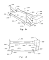
- Figure 14 is a perspective view of an apparatus for pulling a floor liner from the cargo container of Figures 1-3.
- Figure 15 is a top view of the pulling apparatus of Figure 14.
- Figure 16 is a perspective view of a corner casting of the cargo container shown in Figures 1-3.
- Figure 17 is a top view of one of the connecting assemblies of the apparatus of Figures 14 and 15.
- Figure 18 shows the connecting assembly of Figure 17 inserted into the corner casting of Figure 16.
- Figure 19 shows the connecting assembly locked inside the corner casting.
- Figure 20 shows the connecting assembly tightly clamped onto the corner casting.
- Figures 1-3 illustrate cargo container 100 generally comprising container body 102, liner 104, and bulkhead 106.
- container body 102 defines an interior cargo space 110 for holding a cargo; and the container body includes a floor 112, roof 114, front and back walls 116 and 120, and left and right side walls 122 and 124.
- Back wall 120 includes a pair of outwardly hinged doors 120a and 120b, and when these doors are open, the back wall forms an opening that provides access to the interior of the cargo container.
- Liner 104 is positioned on container floor 112 in a sequence of overlapping pleats or folded sections 126 that allow the length of the liner to expand; and the bulkhead 106 is secured inside container body 102, immediately forward of back wall 120, to hold a cargo in cargo space 110.
- a bulk cargo 128 is loaded into cargo space 110 and onto liner 104.
- Suitable inlet openings may be provided in bulkhead 106 to allow the cargo to pass therethrough and into cargo space 110, or the cargo may be conducted into that cargo space through the area above the top of the bulkhead.
- an opening 130 is formed in the bottom of bulkhead 106 and liner 104 is pulled outward from the cargo container.
- cargo 128 is pulled out with the liner; and at the same time, the pleats 126 of the liner unfold, expanding the length of the liner.
- the dimensions of liner 104, particularly the size and number of pleats 126, are selected so that the liner is able to pull out substantially all of the cargo from the container as the liner itself is pulled out of the container cargo.
- a mechanical apparatus is mounted on cargo container 100 to pull liner 104 out therefrom.
- container body 102 has a conventional size and shape. Even more preferably, container body 102 is of the type referred to in the art as intermodal and can be transported by truck, railroad, and ship.
- Figures 4 and 5 illustrate liner 104 in greater detail.
- liner 104 has a generally elongated, rectangular shape, including front and back edges 104a and 104b.
- the folded sections 126 of liner 104 are spaced apart along the length of the liner; and each of the folded sections of the liner extends completely across the width of the liner, substantially perpendicular to the longitudinal axis of the liner.
- the folds are directed toward the back edge of the liner.
- each folded section includes front and back edges; and in each pair of adjacent forward and rearward folded sections, the back edge of the forward one of that pair of sections is positioned on top of the rearward one of that pair of sections.
- four folded sections are specifically referenced at 126a, 126b, 126c, and 126d.
- the front and back edges of section 126a are referenced at 126a-1 and 126a-2 respectively, and the front and back edges of section 126b are referenced at 126b-1 and 126b-2 respectively.
- the front and back edges of section 126c are respectively referenced at 126c-1 and 126c-2, and the front and back edges of section 126c are respectively referenced at 126d-1 and 126d-2.
- the back edge 126a-2 of section 126a is on top of folded section 126b
- the back edge 126b-2 of section 126b is on top of folded section 126c
- the back edge 126c-2 of this latter section is on top of folded section 126d.
- each folded section 126 of liner 104 is chosen to help ensure that cargo 128 is completely unloaded from cargo container 100 as the liner is pulled out therefrom.
- each folded section may have a random width, and these folded sections may be randomly spaced along the length of liner 104. That length is another variable that may be selected to help ensure that cargo 128 is completely unloaded from cargo container 100 as the liner is pulled out therefrom; and indeed, preferably, when the liner is installed in the cargo container, the liner extends at least over the complete length of floor 112, and also partially or completely extend over front wall 116.
- the front portion of liner 104 may be provided with attachment means, such as eyelets or loops to help secure the liner inside cargo container 100; and the back end portion of the liner preferably has truncated corner portions to help pull the liner out of the,cargo container, as discussed in greater detail below.
- small heat welds may be used to connect together folded sections 126 to maintain those folded sections held against each other inside cargo container 100 until liner 104 is pulled out of the container.
- Each heat weld has very little resistance and is broken as soon as an appreciable pulling force is applied to the bottom of the two layers joined by the heat weld.
- Adjacent folded sections may be suitably connected together in other ways, though; and for example, adjacent sections may be stitched together for this purpose.
- FIGS. 6-8 illustrate an alternate liner 134 that may also be used to pull a bulk cargo from cargo container 100, and that includes a multitude of rolled sections 136, rather than a multitude of overlapping pleats 126, spaced along the liner to allow the length of the liner to expand as it is pulled outward from the cargo container.
- Each rolled section 136 includes a section of liner 134 rolled about a given axis.
- the specific number of rolled sections 136 in liner 134, and the size of each rolled section may vary, however, depending on the specific application for which a particular liner is intended.
- Figures 7 and 8 particularly illustrate one procedure that may be used to form rolled sections 136.
- two adjacent portions of liner 134 are brought together, for example as shown at 140, so as to form a top edge 142; and then these two adjacent portions of the liner are progressively rolled together about that edge, as shown at 144a, 144b, 144c, and 144d, until the desired length or amount of material has been rolled together.
- means are applied to the formed roll to hold the material thereof in that roll.
- one or more heated pins 146 may be inserted into or through each roll to prevent the material thereof from prematurely unravelling; and preferably, a multitude of such pins are inserted into each roll at a multitude of locations uniformly spaced along the length of the roll.
- adhesive tape may applied over each roll and connected to adjacent portions of liner 134, on one or both sides of the roll, to prevent the roll from prematurely unravelling.
- Both liners 104 and 134 may be made from any suitable material, although preferably the liners have a high resistance to stretching at least along the lengths of the liners.
- the liners may be constructed of woven polyethylene or woven polypropylene fabric having a thickness of about seven mils.
- the liners may be made from strips, such as two inch strips of fiberglass tape, metal reinforced tape, or polyester reinforced tape, or the liners could be made from co-extruded cross-laminated plastic film, or coextruded, or cross laminated film.
- the liner may be made from natural materials such as cotton.
- bulkhead 106 is secured inside cargo container 100, immediately forward of back wall 120, to hold a cargo in cargo space 110.
- the bulkhead is used to hold the cargo in that space both while the cargo is being loaded thereinto and while the container is being transported.
- a discharge opening must be formed in the bulkhead to allow cargo to be discharged from the cargo container.
- these prior art difficulties are overcome by suspending bulkhead 106 inside cargo container 100 --that is, the bulkhead is supported by a portion of the cargo container other than floor 112 thereof, and for example, the bulkhead may be supported by the sides 122, 124, by the roof 114, or by both the sides and the roof of the cargo container.
- an opening may be formed completely across the bottom of the bulkhead, or a bottom portion of the bulkhead may be removed, to allow cargo to be discharged from the cargo container without significantly interfering with the way in which the bulkhead is supported inside the cargo container.
- Figures 9-13 illustrate a preferred embodiment of bulkhead 106 and various arrangement for suspending the bulkhead inside cargo container 100.
- Figures 9, 11, and 13 also show a pair of reinforcing members or bars 152 that are mounted inside cargo container 100 to reinforce bulkhead 106. More specifically, reinforcing bars 152 are located rearward of bulkhead 106, extend laterally across the bulkhead, and engage both the bulkhead and the cargo container body to transfer loads on the bulkhead to the cargo container body.
- At least one and preferably two straps 154, 156 are connected to upper portions of cargo container 100 and used, either directly or indirectly, to suspend bulkhead 106 therewithin.
- a first end of each strap for example end 156a of strap 156, may be looped over a hook or bar 160 mounted on an inside surface of cargo container 100, and a second end of each strap may be inserted through one or more slits 162 formed in the bulkhead.
- the ends of each strap may be tied or connected together, forming one large loop from strap 154 and one large loop from strap 156 to mount the bulkhead on the cargo container.
- each end of each strap 154, 156 may be tied to a respective adjacent portion of the strap, forming top and bottom smaller loops on strap 154, and top and bottom smaller loops on strap 156 to mount the bulkhead on the cargo container.
- each strap end may be tied to a respective portion of cargo container 100, or to a respective hook or bar mounted on the inside surface of the cargo container, to hold bulkhead 106 thereon.
- straps 154, 156 may be employed to hold reinforcing bars 152 in place; and for example, as generally depicted in Figure 9, each strap may be wrapped or looped around, or simply extend over a respective one side of each of bars 154 and 156, for instance as shown at 164, to hold those bars.
- Figure 11 illustrates a technique for using straps 154, 156 to indirectly suspend bulkhead 106.
- one of the reinforcing bars 152 for example the lower of these two bars, is directly suspended by straps 154 and 156, and then a second set of straps, referenced at 166, are mounted on or wrapped around that one reinforcing bar and used to suspend bulkhead 106.
- straps 154, 156 preferably the lower ends 154b, 156b thereof, are looped around, wrapped around, or otherwise connected to one of the reinforcing bars, preferably to sides thereof, to hold the reinforcing bar in place.
- each of straps 166 is looped or wrapped around or otherwise mounted on the one reinforcing bar and connected to bulkhead 106.
- These straps 166 may be connected to bulkhead 106 in any suitable way; and for example, ends of straps 166 may be inserted through slits 162 and tied together on the front side of the bulkhead. Alternatively, straps 166 may be stapled or glued to the bulkhead.
- a third set of straps 170 may be connected to or mounted on bulkhead 106 and looped or wrapped around the second of the reinforcing bars to hold that bar in its desired position adjacent the bulkhead.
- Figures 12 and 13 illustrate another procedure for suspending bulkhead 106 from one or both of the reinforcing bars 152.
- the ends of that one or both of the reinforcing bars extend into small recesses or notches (one of which is shown at 172 in Figure 13) formed in the side walls 122, 124 of cargo container 100, and are thus directly supported by those side walls, rather than by straps 154, 156.
- a set of straps 174 is wrapped or looped around that reipforcing bar and connected to bulkhead 106 to suspend the bulkhead from that reinforcing bar.
- a second set of straps 176 may be connected to bulkhead 106 and wrapped or looped around the second reinforcing bar to hold that bar in place.
- a set of straps is mounted on either of those bars and connected to the bulkhead to support the bulkhead; and if desired, a second set of straps may be mounted on the other of the reinforcing bars and also connected to the bulkhead to further support the bulkhead.
- Straps 154, 156, 166, 170, 174 may be made of any suitable material, although preferably they are made from a high strength material.
- the straps may be constructed of woven polyethylene and polypropylene, or the straps may be made from strips of fiberglass tapes, metal reinforced tapes, or polyester reinforced tapes.
- the support straps 154, 156, 166, 170, 174 may be made from coextruded cross laminated plastic film, or coextruded, or cross laminated film.
- bulkhead 106 is comprised of upper and lower separable sections 106a and 106b; and in use, the lower section of the bulkhead is separated and removed from the upper section to form a discharge opening or outlet in the bulkhead.
- Bulkhead sections 106a and 106b may be releasably connected together in any suitable manner; and for example, these bulkhead sections may be stapled or nailed,together.
- one of these bulkhead sections may be provided with a plurality of hooks, and the other of the bulkhead sections may be provided with a plurality of openings or eyelets adapted to mount onto those hooks to connect the two bulkhead sections together.
- the bulkhead be comprised of separable sections; and for instance, the bulkhead may be formed from one piece or section of material, and a lower portion or area of the bulkhead may be cut away from an upper portion thereof to form the desired discharge opening in the bulkhead.
- bulkhead 106 is made from a corrugated cardboard material, and is provided with suitable openings or suitable score lines to facilitate the formation of suitable openings, to allow material to be loaded into the cargo container through the bulkhead.
- the bulkhead may be made of any other suitable material, though; and, for instance, the bulkhead may be made from wood.
- reinforcing bars 152 are preferably made from a metal, although these bars may be made from other materials such as wood.
- Figures 14 and 15 illustrate an apparatus 200 for pulling liner 104 outward from cargo container 100; and, generally, this apparatus comprises frame 202, mandrel 204, drive means 206, and connecting means 210.
- Connecting means 210 is mounted on frame 202 to connect unloading apparatus 200 to cargo container 100, preferably immediately rearward of and below the bottom edge of the back opening thereof.
- Mandrel 204 is rotatably supported by and laterally extends across frame 202 and includes means 212 to connect liner 104 to the mandrel, and drive means 206 is mounted on the frame and engages the mandrel to rotate the mandrel to wind the liner therearound and, thereby, to pull the liner outward from cargo container 100.
- frame 202 includes main transverse beam 214, left and right side beams 216 and 220, and left and right stabilizing members 222 and 224.
- Transverse beam 214 is adapted to extend laterally across cargo container 100, immediately adjacent or slightly below the bottom edge of the back opening thereof.
- Left and right side beams 216 and 220 are connected to and extend rearward from the left and right sides, respectively, of beam 214, and mandrel 204 is rotatably supported by and laterally extends between the left and right side members.
- apparatus 200 may tend to pivot upward about main transverse beam 214, and stabilizing members 222 and 224 are provided to limit or to prevent such pivoting movement.
- left and right stabilizing brackets 222 and 224 are connected to and extend upward from the left and right sides of beam 214, respectively; and in case apparatus 200 tends to pivot upward about transverse beam 214, those stabilizing brackets engage or abut against the left and right back sides of cargo container 100, preventing further such pivoting movement and thereby stabilizing frame 202 and the entire unloading apparatus 200 during the unloading process.
- the various members or elements of frame 202 may be made of any suitable material and can be connected together in any suitable way. For instance, these elements may be made from a metal and welded or bolted together.
- Mandrel 204 is rotatably mounted on frame 202; and more specifically, the mandrel is rotatably supported by and laterally extends between side beams 216 and 220 of the frame. To pull a liner 104 from cargo container 100, the back end of that liner is connected to mandrel 204, and then the mandrel is rotated to wind the liner onto and around the mandrel 204.
- the mandrel preferably includes an axially extending slot 212 that radially extends completely through the mandrel; and with particular reference to Figures 4 and 14, to connect liner 104 to mandrel 204, the back edge 104b of the liner is pulled through slot 212. and then the mandrel is rotated to wind the liner onto the mandrel.
- Drive means 206 is mounted on frame 202 and is provided to rotate mandrel 204, and preferably the drive means includes a winch 226 and a motor or engine 230.
- Winch 226 is mounted on frame 202, specifically left side member 216, and is directly connected to mandrel 204 to rotate the mandrel.
- Engine or motor 230 is also mounted on frame 202 and is connected to winch 216 to operate that winch. Any suitable winch, motor, or engine may be used in the practice of the present invention.
- cargo containers of the general type disclosed in Figures 1-3 are transported by trucks or other vehicles that includes a power source, such as a hydraulic pump, an electric battery or an electric generator; and preferably, motor 230 is one that can be operated by the power source on the vehicle that carries the cargo container 100.
- a power source such as a hydraulic pump, an electric battery or an electric generator
- motor 230 is one that can be operated by the power source on the vehicle that carries the cargo container 100.
- this vehicle has a hydraulic pump, it may be preferred to provide unloading apparatus 200 with a hydraulic motor; while if the transporting vehicle has an electric battery or generator, it may be appropriate to provide apparatus 200 with an electric motor.
- Connecting means 210 preferably includes left and right connecting assemblies 232 and 234 mounted, respectively, on the left and right sides of frame 202 to connect the frame, respectively, to left and right sides of cargo container 100.
- An important advantage of apparatus 200 is that the connecting assemblies 232 and 234 thereof are particularly well adapted to mount apparatus 200 onto an intermodal cargo container having conventional, lower back corner castings spaced apart a standard distance.
- corner castings typically have corner members, referred to as corner castings, located at, among other places, the back lower left and back lower right corners of the container body.
- corner castings One corner casting is shown at 236 in Figure 18; and as illustrated therein, the corner castings form a multitude of openings 240 that are used to lock the cargo containers onto supporting members such as trucks or railroad car frames or other containers. Because of the way in which these corner castings are used, industry standards have developed that govern the size, shape, and spacing of the corner castings.
- connecting assemblies 232 and 234 are specifically designed to lock into corner castings, and second, are spaced apart a distance substantially equal to a standard distance between such corner castings.
- each of the connecting assemblies includes twist lock 242, handle 244, spacer 246, support rod 250, and adjusting nut 252.
- Twist lock 242 is rotatably mounted on frame 202, specifically transverse beam 214, adjacent one end thereof; and handle 244 is connected to the twist lock to pivot that lock to facilitate inserting the twist lock into, and then locking it inside, one of the corner castings of cargo container 100. More specifically, twist lock 242 is pivotal between, and handle 244 is used to pivot the twist lock between, first and second positions shown in Figures 18 and 19, respectively.
- twist lock 242 In this first position, twist lock 242 can be inserted through an opening 240 in, and into the interior of, corner casting 236; and in the second position,,twist lock 242 is locked inside corner casting 236.
- twist lock 242 is disposed on a forward or front side of beam 214, and handle 244 is disposed on a rearward or back side of that beam.
- Twist lock 242 may be pivotally mounted on beam 214 and handle 244 may be connected to the twist lock in any suitable way.
- a through opening 254 may be formed in beam 214, and rod 250 may be inserted through that opening such that the rod is supported by beam 214 and is rotatable in opening 254.
- twist lock 242 is rigidly mounted on a forward end of rod 250, and handle 244 is connected to a back end of rod 250.
- Spacing member 246 is connected to transverse beam 214, between that beam and twist lock 242, to maintain the twist lock spaced from the transverse beam. This facilitates inserting the twist lock into the interior of corner casting 236 and locking the twist lock therein. As shown in Figure 17, preferably, support rod 250 also extends through spacing member 246.
- each connecting assembly 232 and 234 also includes tightening means connected to the twist lock to pull the twist lock toward transverse beam 214 and thereby to connect frame 202 tightly to a respective one of the corner casting members on container 100.
- this tightening means comprises adjusting nut 252, which is threadably mounted on rod 250, rearward of beam 214.
- nut 252 is threaded forward on rod 250 to bring the nut into engagement with the backside of beam 214 and then to pull rod 250 and twist lock 242 rearward, thereby clamping the corner casting securely between twist lock 242 and beam 214, as shown in Figure 22.
Landscapes
- Engineering & Computer Science (AREA)
- Mechanical Engineering (AREA)
- Transportation (AREA)
- Loading Or Unloading Of Vehicles (AREA)
- Load-Engaging Elements For Cranes (AREA)
- Filling Or Discharging Of Gas Storage Vessels (AREA)
- Ship Loading And Unloading (AREA)
- Filling Or Emptying Of Bunkers, Hoppers, And Tanks (AREA)
Claims (12)
- Frachtbehälter, der aufweist:einen Behälterkörper (102), der einen Boden (112) und eine vordere Wand (116) aufweist, und der einen Frachtraum (110), der eine Fracht enthalten kann, und eine hintere Öffnung (120) zum Einladen von Fracht in den Frachtraum (110) und zum Ausladen von Fracht aus diesem definiert, undeinen Belag (104), der sich auf dem Boden (112) in einer Folge von sich überdeckenden gefalteten Abschnitten (126) befindet, um die Länge des Belages (104) zu erhöhen, wenn der Belag (104) von der hinteren Öffnung (120) weggezogen wird, um die Fracht aus dem Frachtbehälter (100) auszugeben,wobei sich der Belag (104) im Behälterkörper (102) von der hinteren Öffnung (120) weg zumindest im wesentlichen vollständig zwischen der hinteren Öffnung (120) und der vorderen Wand (116) des Behälterkörpers (102) nach vorn erstreckt,dadurch gekennzeichnet, daßüber im wesentlichen die gesamte Länge des Belages (104) in jedem Paar benachbarter vorderer und hinterer gefalteter Abschnitte (126) die vordere Kante (126a-2) des vorderen Abschnitts (126a) des Paars von Abschnitten die hintere Kante (126b) des hinteren Abschnitts (126b) des Paars von Abschnitten überdeckt, wobei sich die vorderen Kanten (126a-2 bis 126d-2) zur hinteren Öffnung (120) des Behälters erstrecken, wobeisich die sich überdeckenden gefalteten Abschnitte (126) über die Länge des Belagflachmaterials (104) mit zufälligem Abstand oder gleichem Abstand erstrecken.
- Frachtbehälter nach Anspruch 1, bei dem die gefalteten Abschnitte (126) miteinander verbunden sind, um die gefalteten Abschnitte (126) gegeneinander zusammenzuhalten, bis der Belag (104) aus dem Behälter (102) herausgezogen wird.
- Frachtbehälter, der aufweist:einen Behälterkörper (102), der einen Boden (112) aufweist, und der einen Frachtraum (110), der eine Fracht enthalten kann, und eine hintere Öffnung (120) zum Einladen von Fracht in den Frachtraum (110) und zum Ausladen von Fracht aus diesem definiert, undeinen Belag (134), der sich auf dem Boden in einer Folge von gefalteten Abschnitten befindet, um die Länge des Belages zu erhöhen, wenn der Belag von der hinteren Öffnung weggezogen wird, um die Fracht aus dem Frachtbehälter auszugeben,dadurch gekennzeichnet, daßdie gefalteten Abschnitte auf sich selbst zur hinteren Öffnung (120) des Behälters hin aufgerollt sind, um zu gestatten, daß sich die Länge des Belages (134) erhöht, wenn der Belag (134) von der hinteren Öffnung (120) weggezogen wird, um die Fracht aus dem Frachtbehälter (100) auszugeben, wobeidie gerollten Abschnitte (136) über die Länge des Belages (134) zufällig zueinander beabstandet sind, und/oderüber die Länge des Belages (134) gleichmäßig beabstandet sind.
- Frachtbehälter nach Anspruch 3, bei demder Belag (134) eine erste Längsachse festlegt undjeder gerollte Abschnitt (136) eine jeweilige zweite Längsachse definiert, die sich im wesentlichen senkrecht zur Längsachse des Belages (104) erstreckt, wobeijeder der gerollten Abschnitte (136) aufweist:einen Abschnitt des Belages (104), der um eine Achse und zu einer Rolle gerollt ist, undeine Einrichtung (146), die die Rolle um die Achse hält, und/oder wobeidie Halteeinrichtung von jedem gerollten Abschnitt (136) zumindest einen Wärmestift (146) aufweist, der sich in die Rolle des gerollten Abschnitts (136) erstreckt.
- Frachtbehälter nach einem der vorhergehenden Ansprüche, bei dem der Belag (104, 134) aus gewebten textilen Polyethylen- oder Polypropylenflächengebilde ist.
- Verfahren zum Einladen und Ausladen von Schüttgut, insbesondere von einem Frachtbehälter von dem Typ nach Anspruch 1 bis 2 oder 3 bis 5, das die Schritte aufweist:Positionieren eines Belages (134), der eine Vielzahl von gefalteten oder gerollten Abschnitten (126, 136) aufweist, die über die Länge des Belages (104, 134) angeordnet sind, auf dem Boden (112),Einladen eines Schüttgutes in den Frachtraum (110) und auf den Belag (104, 134), undZiehen des Belages (104, 134) von der hinteren Öffnung (120) des Frachtbehälters (100) weg nach außen, um die Fracht aus dem Frachtraum (110) auszuladen, wobei die gefalteten oder gerollten Abschnitte (126, 136) ermöglichen, daß die Länge des Belages (104, 134) zunimmt, wenn der Belag (104, 134) herausgezogen wird, wobeider Herausziehschritt den Schritt des Entfaltens oder Entrollens von jedem gefalteten oder gerollten Abschnitt (126, 136) einzeln in Reihe über die Länge des Belages (104, 134) aufweist, wenn der Belag (104, 134) herausgezogen wird, und/oder wobeider Positionierschritt den Schritt des zufälligen und/oder gleichmäßigen Beabstandens der gefalteten oder gerollten Abschnitte (126, 136) über die Länge des Belages (104, 134) aufweist.
- Verfahren nach Anspruch 6, bei dem der Positionierschritt den Schritt des Ausbilden des Belages (134) aus einem Bogen von Material aufweist, das die Schritte aufweist:Falten benachbarter Abschnitte des Bogens gegeneinander, um einen gefalteten Abschnitt (140) mit einer oberen Kante (142) auszubilden, an einer Vielzahl von ausgewählten Positionen über die Länge des Bogens, undRollen von jedem gefalteten Abschnitt (140) auf sich selbst um die obere Kante (142) des gefalteten Abschnitts, um eine Rolle (136) von Material auszubilden, wobeinach dem Abschließen des Rollschritts der Ausbildeschritt den weiteren Schritt des Haltens von jeder Rolle von Material in einer Rolle (136) aufweist und/oder wobeider Halteschritt den Schritt des Ausbildens von zumindest einem Stiftwärmeverschluß (146) in jeder Rolle (136) aufweist und/oderder Halteschritt den Schritt des Aufbringens von einem Klebeband auf jede Rolle (136) von Material aufweist, um zu verhindern, daß sich die Rolle (136) entrollt.
- Verfahren nach Anspruch 6 oder 7, bei dem
die gefalteten Abschnitte (140) im wesentlichen gleichmäßige Breiten haben, bevor jeder gefaltete Abschnitt gerollt wird. - Verfahren nach einem der Ansprüche 6 bis 8, das die Schritte aufweist:Montage einer Entladevorrichtung (200) direkt auf dem Frachtbehälter (100) benachbart zur hinteren Öffnung (120),Verbinden des Belages (104, 134) mit der Entladevorrichtung (200), undwährend die Entladevorrichtung (200) auf dem Frachtbehälter (100) direkt montiert ist, Betätigen der Entladevorrichtung (200), um den Belag (104, 134) und das Schüttgut aus dem Frachtbehälter (100) durch die hintere Öffnung (120) von diesem herauszuziehen.
- Verfahren nach Anspruch 9, das die Schritt aufweist:Verbinden der Entladevorrichtung (200) mit der Energieversorgung, undVerwenden der Energieversorgung (230), um die Entladevorrichtung (200) zu betätigen, wobeidie Energieversorgung eine Elektroenergieversorgung oder eine Hydroenergieversorgung ist.
- Verfahren nach Anspruch 9 oder 10, wobei die Entladevorrichtung (200) eine drehbare Spindel (204) aufweist, die eine sich axial und radial erstreckende Vertiefung (212) aufweist und wobeider Verbindungsschritt den Schritt des Einführens des Belages (104, 134) in die Vertiefung (212) aufweist, undder Betätigungsschritt den Schritt des Drehens der Spindel (204) aufweist, um den Belag (104, 134) um diese herumzuwickeln.
- Verfahren nach einem der Ansprüche 9 bis 11, wobei der Frachtbehälter (100) linke und rechte untere Eckelemente (236) benachbart zur hinteren Öffnung des Frachtbehälters aufweist, wobei jedes der Eckelemente eine Öffnung (240) ausbildet, und die Entladevorrichtung (200) linke und rechte Verdrehverschlüsse (242) aufweist, und wobei der Montageschritt die Schritte aufweist:Einführen des linken und rechten Verdrehverschlusses (242) in die Öffnungen (240) im linken bzw. rechten unteren Eckelement (236),Verriegeln des linken Verdrehverschlusses (242) im linken Eckelement (236), undVerriegeln des rechten Verdrehverschlusses (242) im rechten Eckelement (236), wobei der Montageschritt ferner die Schritte aufweist:starkes Festklemmen der Entladevorrichtung (200) am linken Eckelement (236) nachdem der linke Verdrehverschluß (242) in diesem verriegelt wurde, undstarkes Festklemmen der Entladevorrichtung (200) am rechten Eckelement (236), nachdem der rechte Verdrehverschluß (242) in diesem verriegelt wurde.
Priority Applications (1)
| Application Number | Priority Date | Filing Date | Title |
|---|---|---|---|
| EP95118085A EP0712794A1 (de) | 1991-07-18 | 1992-07-17 | Behälter mit Innenauskleidung und Schott |
Applications Claiming Priority (3)
| Application Number | Priority Date | Filing Date | Title |
|---|---|---|---|
| US73245191A | 1991-07-18 | 1991-07-18 | |
| US732451 | 1991-07-18 | ||
| PCT/US1992/006008 WO1993002004A2 (en) | 1991-07-18 | 1992-07-17 | Cargo container and method of unloading the same |
Related Child Applications (1)
| Application Number | Title | Priority Date | Filing Date |
|---|---|---|---|
| EP95118085.0 Division-Into | 1995-11-16 |
Publications (2)
| Publication Number | Publication Date |
|---|---|
| EP0593678A1 EP0593678A1 (de) | 1994-04-27 |
| EP0593678B1 true EP0593678B1 (de) | 1997-06-04 |
Family
ID=24943546
Family Applications (2)
| Application Number | Title | Priority Date | Filing Date |
|---|---|---|---|
| EP95118085A Withdrawn EP0712794A1 (de) | 1991-07-18 | 1992-07-17 | Behälter mit Innenauskleidung und Schott |
| EP92917049A Expired - Lifetime EP0593678B1 (de) | 1991-07-18 | 1992-07-17 | Frachtbehälter und Verfahren zu dessen Entladung |
Family Applications Before (1)
| Application Number | Title | Priority Date | Filing Date |
|---|---|---|---|
| EP95118085A Withdrawn EP0712794A1 (de) | 1991-07-18 | 1992-07-17 | Behälter mit Innenauskleidung und Schott |
Country Status (8)
| Country | Link |
|---|---|
| US (3) | US5454685A (de) |
| EP (2) | EP0712794A1 (de) |
| JP (1) | JPH06509050A (de) |
| AU (1) | AU2392892A (de) |
| BR (1) | BR9206291A (de) |
| CA (1) | CA2113253A1 (de) |
| DE (1) | DE69220227T2 (de) |
| WO (1) | WO1993002004A2 (de) |
Cited By (1)
| Publication number | Priority date | Publication date | Assignee | Title |
|---|---|---|---|---|
| US20220274772A1 (en) * | 2019-11-21 | 2022-09-01 | Oswaldo Mino | Liner and method for unloading bulk cargo |
Families Citing this family (16)
| Publication number | Priority date | Publication date | Assignee | Title |
|---|---|---|---|---|
| US6408572B1 (en) * | 1998-06-03 | 2002-06-25 | Mitsuba Corporation | Driving gear |
| USD483949S1 (en) | 2002-02-06 | 2003-12-23 | Salton, Inc. | Surface pattern for a storage container for a personal care product |
| GB2376013B (en) * | 2002-05-01 | 2003-07-23 | Pickfords Ltd | A bulkhead assembly for use in a shipping container and a method of forming such a bulkhead assembly |
| US6824223B2 (en) * | 2002-06-13 | 2004-11-30 | Ez Lift Backsaver, Inc. | Utility cart unloading system |
| US7320572B2 (en) * | 2003-01-21 | 2008-01-22 | Smith Fred P | Cargo unloading apparatus and method |
| US20060033377A1 (en) * | 2004-08-13 | 2006-02-16 | Frimel Dale M | Laterally moving, sectional, material-dumping, vehicle bed conversion unit |
| US20060078412A1 (en) * | 2004-10-08 | 2006-04-13 | Rapco L.L.C. | Apparatus for storing material |
| US8226109B2 (en) * | 2006-03-17 | 2012-07-24 | William J Ritter | Splitboard bindings |
| US7837428B2 (en) | 2007-03-05 | 2010-11-23 | SA Recycling LLC | Methods and apparatuses for freight container loading |
| US8668425B2 (en) | 2007-03-05 | 2014-03-11 | SA Recycling LLC | Methods and apparatus for freight container loading |
| DE102007032017B4 (de) * | 2007-05-16 | 2011-01-27 | Bayer Materialscience Ag | Verfahren zum Befüllen und Entleeren von Transport-Containern mit Kunststoffgranulaten |
| US20100086386A1 (en) * | 2008-10-08 | 2010-04-08 | Freeman Brint D | Car slider assembly |
| KR100973112B1 (ko) | 2008-10-22 | 2010-07-29 | 두산엔진주식회사 | 대형 저속엔진용 승강이동 블록 |
| WO2018022449A1 (en) | 2016-07-24 | 2018-02-01 | D&Bd Marketing, Llc Dba Bulk-Flow | Tilt-less liner apparatus and system for unloading bulk cargo |
| PL3684716T3 (pl) | 2017-09-19 | 2024-08-19 | Move Intermodal Nv | System rozładunkowy zawierający zbiornik zasypowy i naczepę |
| US11142394B1 (en) * | 2021-04-29 | 2021-10-12 | The DeLong Co., Inc. | Bulkhead securement system and method for intermodal shipment of dry flowable commodities |
Citations (1)
| Publication number | Priority date | Publication date | Assignee | Title |
|---|---|---|---|---|
| CA1205106A (en) * | 1983-04-27 | 1986-05-27 | Victor Podd | Bulk puller for unloading containers |
Family Cites Families (37)
| Publication number | Priority date | Publication date | Assignee | Title |
|---|---|---|---|---|
| US2477707A (en) * | 1946-04-27 | 1949-08-02 | Deere & Co | Self-unloading vehicle |
| US2595395A (en) * | 1948-11-20 | 1952-05-06 | Thomas B Lavelle | Power unit and wagon unloader |
| US2764304A (en) * | 1952-11-29 | 1956-09-25 | Jr Lawrence E Johnson | Farm wagon unloading mechanism |
| US2895431A (en) * | 1957-04-22 | 1959-07-21 | Ford Grain Door Company | Freight car bulkhead |
| US2949866A (en) * | 1957-06-21 | 1960-08-23 | Int Paper Co | Freight car bulkhead |
| US2989011A (en) * | 1958-01-16 | 1961-06-20 | Pacific Car & Foundry Co | Vertical partitions for railway cars |
| US3164395A (en) * | 1962-09-17 | 1965-01-05 | Baker & Co Hugh J | Cargo gate |
| US3297175A (en) * | 1964-11-03 | 1967-01-10 | Western Velo & Cement Specialt | Bulkhead structure |
| US3443703A (en) * | 1967-01-16 | 1969-05-13 | Tom T Matsumoto | Dumping apparatus |
| US3427997A (en) * | 1967-05-19 | 1969-02-18 | Neuberne H Brown Jr | Inflatable bulkhead for railroad car |
| DE1951888A1 (de) * | 1969-10-15 | 1971-04-22 | Scholtz Ag Conrad | Transportbehaelter fuer fluessige und fliessende Gueter und/oder Stueckgueter |
| US3696952A (en) * | 1970-03-23 | 1972-10-10 | Sea Land Service | Bulk cargo handling system and method |
| US3704798A (en) * | 1971-02-03 | 1972-12-05 | Greif Bros Corp | Truck cargo transfer assembly |
| NL7302756A (de) * | 1972-03-04 | 1973-09-07 | ||
| US4054226A (en) * | 1973-11-16 | 1977-10-18 | United States Lines, Inc. | Lining of containers for bulk cargo |
| US3886544A (en) * | 1974-06-12 | 1975-05-27 | Leo H Narodny | Keyboard using optical switching |
| US3978996A (en) * | 1975-01-15 | 1976-09-07 | Victor Conrad Oltrogge | Tailgate unloader |
| US4168667A (en) * | 1977-08-01 | 1979-09-25 | Unarco Industries, Inc. | Curtain for lading protection |
| US4265577A (en) * | 1979-05-31 | 1981-05-05 | Unarco Industries, Inc. | Two-piece curtain-like lading-restraining device |
| US4277220A (en) * | 1980-01-31 | 1981-07-07 | Wiley Frederick R | Combined load cover and unloader |
| CA1130963A (en) * | 1980-07-28 | 1982-09-07 | Don Andrews | Apparatus for drying fish, especially squid |
| NL8102845A (nl) * | 1981-06-12 | 1983-01-03 | Leer Koninklijke Emballage | Werkwijze voor het lossen van stortgoed uit een laadbak of laadkist alsmede laadbak of laadkist voor het uitvoeren van de werkwijze. |
| US4436466A (en) * | 1981-08-03 | 1984-03-13 | Marino Frank J | Cargo restraining apparatus |
| AU551301B2 (en) * | 1982-03-10 | 1986-04-24 | Grant, James Barry | Conveyor unloader |
| NL8201634A (nl) * | 1982-04-20 | 1983-11-16 | Leer Koninklijke Emballage | Schot voor een laadbak voor stortgoed. |
| US4405089A (en) * | 1982-09-28 | 1983-09-20 | Tarrant Manufacturing Company | Multiple conveyor |
| US5244332A (en) * | 1983-06-09 | 1993-09-14 | Bjk Industries, Inc. | Bulk loading method and apparatus |
| US4629390A (en) * | 1984-10-31 | 1986-12-16 | Burke Donald D | Truck bed unloader |
| JPH0213346Y2 (de) * | 1985-06-29 | 1990-04-12 | ||
| CA1239052A (en) * | 1986-06-23 | 1988-07-12 | Joseph W. Cox | Adjustable load retainer and retention means for use in a transport vehicle |
| US4749325A (en) * | 1986-09-11 | 1988-06-07 | Rolflor Industries, Inc. | Method and apparatus for loading trucks |
| US4773802A (en) * | 1987-01-09 | 1988-09-27 | Rewis Jerry L | Freight cover |
| US4892456A (en) * | 1988-02-04 | 1990-01-09 | Rolflor Industries, Inc. | Unloading system for freight containers |
| US4842471A (en) * | 1988-05-17 | 1989-06-27 | Rolflor Industries, Inc. | Unloading mechanism for trucks and trailers |
| US4948325A (en) * | 1988-08-30 | 1990-08-14 | Rolflor Industries | Control apparatus for a loading-moving system |
| JPH0518313Y2 (de) * | 1988-11-18 | 1993-05-14 | ||
| CA2007045C (en) * | 1989-01-10 | 1996-06-25 | Keiji Ishii | Interior bag for a container |
-
1992
- 1992-07-17 DE DE69220227T patent/DE69220227T2/de not_active Expired - Fee Related
- 1992-07-17 AU AU23928/92A patent/AU2392892A/en not_active Abandoned
- 1992-07-17 WO PCT/US1992/006008 patent/WO1993002004A2/en not_active Ceased
- 1992-07-17 BR BR9206291A patent/BR9206291A/pt not_active Application Discontinuation
- 1992-07-17 EP EP95118085A patent/EP0712794A1/de not_active Withdrawn
- 1992-07-17 EP EP92917049A patent/EP0593678B1/de not_active Expired - Lifetime
- 1992-07-17 JP JP5502991A patent/JPH06509050A/ja active Pending
- 1992-07-17 CA CA002113253A patent/CA2113253A1/en not_active Abandoned
-
1993
- 1993-12-23 US US08/173,704 patent/US5454685A/en not_active Expired - Fee Related
-
1995
- 1995-01-05 US US08/369,258 patent/US5520496A/en not_active Expired - Fee Related
- 1995-01-25 US US08/378,070 patent/US5564891A/en not_active Expired - Fee Related
Patent Citations (1)
| Publication number | Priority date | Publication date | Assignee | Title |
|---|---|---|---|---|
| CA1205106A (en) * | 1983-04-27 | 1986-05-27 | Victor Podd | Bulk puller for unloading containers |
Cited By (2)
| Publication number | Priority date | Publication date | Assignee | Title |
|---|---|---|---|---|
| US20220274772A1 (en) * | 2019-11-21 | 2022-09-01 | Oswaldo Mino | Liner and method for unloading bulk cargo |
| US12012278B2 (en) * | 2019-11-21 | 2024-06-18 | Oswaldo Mino | Liner and method for unloading bulk cargo |
Also Published As
| Publication number | Publication date |
|---|---|
| JPH06509050A (ja) | 1994-10-13 |
| BR9206291A (pt) | 1994-08-02 |
| US5520496A (en) | 1996-05-28 |
| DE69220227D1 (de) | 1997-07-10 |
| DE69220227T2 (de) | 1997-10-30 |
| WO1993002004A2 (en) | 1993-02-04 |
| WO1993002004A3 (en) | 1993-04-01 |
| EP0712794A1 (de) | 1996-05-22 |
| AU2392892A (en) | 1993-02-23 |
| CA2113253A1 (en) | 1993-02-04 |
| US5454685A (en) | 1995-10-03 |
| EP0593678A1 (de) | 1994-04-27 |
| US5564891A (en) | 1996-10-15 |
Similar Documents
| Publication | Publication Date | Title |
|---|---|---|
| EP0593678B1 (de) | Frachtbehälter und Verfahren zu dessen Entladung | |
| US5653572A (en) | Conveyor sheet cargo container and method | |
| EP0540695B1 (de) | Eine innenverkleidung fuer einen frachtcontainer und ein verfahren, eine innenverkleidung in einem frachtcontainer anzubringen | |
| AU655141B2 (en) | Floating hanging liner support | |
| US5152735A (en) | Bracing system for a liner for a cargo container | |
| US5318193A (en) | Bracing system for a liner for a cargo container | |
| US5547331A (en) | Method for loading bulk material into a cargo container with an aeration/vacuum liner pad system | |
| EP0627369A2 (de) | Behälter mit Schott und mehreren, verankerten und geheizten Auskleidungen | |
| US8083412B2 (en) | Methods and apparatus for transporting bulk products | |
| CA1205106A (en) | Bulk puller for unloading containers | |
| AU705106B2 (en) | Conveyor sheet cargo container and method | |
| US5167472A (en) | Method for unloading bulk cargo from a modular cargo container | |
| EP3684716B1 (de) | Entladesystem mit einem trichter und einem anhänger | |
| AU719432B2 (en) | Lining for container | |
| JPH0212234Y2 (de) | ||
| AU2074900A (en) | Lining for container |
Legal Events
| Date | Code | Title | Description |
|---|---|---|---|
| PUAI | Public reference made under article 153(3) epc to a published international application that has entered the european phase |
Free format text: ORIGINAL CODE: 0009012 |
|
| 17P | Request for examination filed |
Effective date: 19940118 |
|
| AK | Designated contracting states |
Kind code of ref document: A1 Designated state(s): BE DE ES FR GB IT NL |
|
| 17Q | First examination report despatched |
Effective date: 19950224 |
|
| GRAG | Despatch of communication of intention to grant |
Free format text: ORIGINAL CODE: EPIDOS AGRA |
|
| GRAH | Despatch of communication of intention to grant a patent |
Free format text: ORIGINAL CODE: EPIDOS IGRA |
|
| GRAH | Despatch of communication of intention to grant a patent |
Free format text: ORIGINAL CODE: EPIDOS IGRA |
|
| GRAA | (expected) grant |
Free format text: ORIGINAL CODE: 0009210 |
|
| AK | Designated contracting states |
Kind code of ref document: B1 Designated state(s): BE DE ES FR GB IT NL |
|
| DX | Miscellaneous (deleted) | ||
| PG25 | Lapsed in a contracting state [announced via postgrant information from national office to epo] |
Ref country code: IT Free format text: LAPSE BECAUSE OF FAILURE TO SUBMIT A TRANSLATION OF THE DESCRIPTION OR TO PAY THE FEE WITHIN THE PRE;WARNING: LAPSES OF ITALIAN PATENTS WITH EFFECTIVE DATE BEFORE 2007 MAY HAVE OCCURRED AT ANY TIME BEFORE 2007. THE CORRECT EFFECTIVE DATE MAY BE DIFFERENT FROM THE ONE RECORDED.SCRIBED TIME-LIMIT Effective date: 19970604 Ref country code: FR Effective date: 19970604 Ref country code: ES Free format text: THE PATENT HAS BEEN ANNULLED BY A DECISION OF A NATIONAL AUTHORITY Effective date: 19970604 |
|
| REF | Corresponds to: |
Ref document number: 69220227 Country of ref document: DE Date of ref document: 19970710 |
|
| EN | Fr: translation not filed | ||
| PLBE | No opposition filed within time limit |
Free format text: ORIGINAL CODE: 0009261 |
|
| 26N | No opposition filed | ||
| PGFP | Annual fee paid to national office [announced via postgrant information from national office to epo] |
Ref country code: GB Payment date: 19990708 Year of fee payment: 8 |
|
| PGFP | Annual fee paid to national office [announced via postgrant information from national office to epo] |
Ref country code: BE Payment date: 19990728 Year of fee payment: 8 |
|
| PGFP | Annual fee paid to national office [announced via postgrant information from national office to epo] |
Ref country code: NL Payment date: 19990730 Year of fee payment: 8 |
|
| PGFP | Annual fee paid to national office [announced via postgrant information from national office to epo] |
Ref country code: DE Payment date: 19990928 Year of fee payment: 8 |
|
| PG25 | Lapsed in a contracting state [announced via postgrant information from national office to epo] |
Ref country code: GB Free format text: LAPSE BECAUSE OF NON-PAYMENT OF DUE FEES Effective date: 20000717 |
|
| PG25 | Lapsed in a contracting state [announced via postgrant information from national office to epo] |
Ref country code: BE Free format text: LAPSE BECAUSE OF NON-PAYMENT OF DUE FEES Effective date: 20000731 |
|
| BERE | Be: lapsed |
Owner name: PODD VICTOR I. JR. Effective date: 20000731 Owner name: PODD STEPHEN D. Effective date: 20000731 |
|
| PG25 | Lapsed in a contracting state [announced via postgrant information from national office to epo] |
Ref country code: NL Free format text: LAPSE BECAUSE OF NON-PAYMENT OF DUE FEES Effective date: 20010201 |
|
| GBPC | Gb: european patent ceased through non-payment of renewal fee |
Effective date: 20000717 |
|
| NLV4 | Nl: lapsed or anulled due to non-payment of the annual fee |
Effective date: 20010201 |
|
| PG25 | Lapsed in a contracting state [announced via postgrant information from national office to epo] |
Ref country code: DE Free format text: LAPSE BECAUSE OF NON-PAYMENT OF DUE FEES Effective date: 20010501 |