EP0593712B1 - Reservoir a compartiments pour fluides - Google Patents
Reservoir a compartiments pour fluides Download PDFInfo
- Publication number
- EP0593712B1 EP0593712B1 EP93909152A EP93909152A EP0593712B1 EP 0593712 B1 EP0593712 B1 EP 0593712B1 EP 93909152 A EP93909152 A EP 93909152A EP 93909152 A EP93909152 A EP 93909152A EP 0593712 B1 EP0593712 B1 EP 0593712B1
- Authority
- EP
- European Patent Office
- Prior art keywords
- fluid
- containment means
- channel
- tank
- containment
- Prior art date
- Legal status (The legal status is an assumption and is not a legal conclusion. Google has not performed a legal analysis and makes no representation as to the accuracy of the status listed.)
- Expired - Lifetime
Links
- 239000012530 fluid Substances 0.000 title claims abstract description 179
- 238000005192 partition Methods 0.000 claims description 7
- 230000003137 locomotive effect Effects 0.000 description 9
- 239000002828 fuel tank Substances 0.000 description 7
- 239000000446 fuel Substances 0.000 description 6
- 230000009977 dual effect Effects 0.000 description 2
- 230000000694 effects Effects 0.000 description 2
- 230000002457 bidirectional effect Effects 0.000 description 1
- 230000005574 cross-species transmission Effects 0.000 description 1
- 238000001514 detection method Methods 0.000 description 1
- 239000000383 hazardous chemical Substances 0.000 description 1
- 231100000614 poison Toxicity 0.000 description 1
- 230000000153 supplemental effect Effects 0.000 description 1
- 239000003440 toxic substance Substances 0.000 description 1
- 230000001960 triggered effect Effects 0.000 description 1
Images



Classifications
-
- F—MECHANICAL ENGINEERING; LIGHTING; HEATING; WEAPONS; BLASTING
- F02—COMBUSTION ENGINES; HOT-GAS OR COMBUSTION-PRODUCT ENGINE PLANTS
- F02M—SUPPLYING COMBUSTION ENGINES IN GENERAL WITH COMBUSTIBLE MIXTURES OR CONSTITUENTS THEREOF
- F02M37/00—Apparatus or systems for feeding liquid fuel from storage containers to carburettors or fuel-injection apparatus; Arrangements for purifying liquid fuel specially adapted for, or arranged on, internal-combustion engines
- F02M37/0047—Layout or arrangement of systems for feeding fuel
- F02M37/007—Layout or arrangement of systems for feeding fuel characterised by its use in vehicles, in stationary plants or in small engines, e.g. hand held tools
-
- B—PERFORMING OPERATIONS; TRANSPORTING
- B60—VEHICLES IN GENERAL
- B60K—ARRANGEMENT OR MOUNTING OF PROPULSION UNITS OR OF TRANSMISSIONS IN VEHICLES; ARRANGEMENT OR MOUNTING OF PLURAL DIVERSE PRIME-MOVERS IN VEHICLES; AUXILIARY DRIVES FOR VEHICLES; INSTRUMENTATION OR DASHBOARDS FOR VEHICLES; ARRANGEMENTS IN CONNECTION WITH COOLING, AIR INTAKE, GAS EXHAUST OR FUEL SUPPLY OF PROPULSION UNITS IN VEHICLES
- B60K15/00—Arrangement in connection with fuel supply of combustion engines or other fuel consuming energy converters, e.g. fuel cells; Mounting or construction of fuel tanks
- B60K15/03—Fuel tanks
- B60K15/03177—Fuel tanks made of non-metallic material, e.g. plastics, or of a combination of non-metallic and metallic material
-
- B—PERFORMING OPERATIONS; TRANSPORTING
- B60—VEHICLES IN GENERAL
- B60K—ARRANGEMENT OR MOUNTING OF PROPULSION UNITS OR OF TRANSMISSIONS IN VEHICLES; ARRANGEMENT OR MOUNTING OF PLURAL DIVERSE PRIME-MOVERS IN VEHICLES; AUXILIARY DRIVES FOR VEHICLES; INSTRUMENTATION OR DASHBOARDS FOR VEHICLES; ARRANGEMENTS IN CONNECTION WITH COOLING, AIR INTAKE, GAS EXHAUST OR FUEL SUPPLY OF PROPULSION UNITS IN VEHICLES
- B60K15/00—Arrangement in connection with fuel supply of combustion engines or other fuel consuming energy converters, e.g. fuel cells; Mounting or construction of fuel tanks
- B60K15/03—Fuel tanks
- B60K15/077—Fuel tanks with means modifying or controlling distribution or motion of fuel, e.g. to prevent noise, surge, splash or fuel starvation
-
- B—PERFORMING OPERATIONS; TRANSPORTING
- B65—CONVEYING; PACKING; STORING; HANDLING THIN OR FILAMENTARY MATERIAL
- B65D—CONTAINERS FOR STORAGE OR TRANSPORT OF ARTICLES OR MATERIALS, e.g. BAGS, BARRELS, BOTTLES, BOXES, CANS, CARTONS, CRATES, DRUMS, JARS, TANKS, HOPPERS, FORWARDING CONTAINERS; ACCESSORIES, CLOSURES, OR FITTINGS THEREFOR; PACKAGING ELEMENTS; PACKAGES
- B65D90/00—Component parts, details or accessories for large containers
- B65D90/22—Safety features
-
- F—MECHANICAL ENGINEERING; LIGHTING; HEATING; WEAPONS; BLASTING
- F02—COMBUSTION ENGINES; HOT-GAS OR COMBUSTION-PRODUCT ENGINE PLANTS
- F02M—SUPPLYING COMBUSTION ENGINES IN GENERAL WITH COMBUSTIBLE MIXTURES OR CONSTITUENTS THEREOF
- F02M37/00—Apparatus or systems for feeding liquid fuel from storage containers to carburettors or fuel-injection apparatus; Arrangements for purifying liquid fuel specially adapted for, or arranged on, internal-combustion engines
- F02M37/0076—Details of the fuel feeding system related to the fuel tank
- F02M37/0088—Multiple separate fuel tanks or tanks being at least partially partitioned
-
- B—PERFORMING OPERATIONS; TRANSPORTING
- B60—VEHICLES IN GENERAL
- B60K—ARRANGEMENT OR MOUNTING OF PROPULSION UNITS OR OF TRANSMISSIONS IN VEHICLES; ARRANGEMENT OR MOUNTING OF PLURAL DIVERSE PRIME-MOVERS IN VEHICLES; AUXILIARY DRIVES FOR VEHICLES; INSTRUMENTATION OR DASHBOARDS FOR VEHICLES; ARRANGEMENTS IN CONNECTION WITH COOLING, AIR INTAKE, GAS EXHAUST OR FUEL SUPPLY OF PROPULSION UNITS IN VEHICLES
- B60K15/00—Arrangement in connection with fuel supply of combustion engines or other fuel consuming energy converters, e.g. fuel cells; Mounting or construction of fuel tanks
- B60K15/03—Fuel tanks
- B60K2015/03118—Multiple tanks, i.e. two or more separate tanks
-
- B—PERFORMING OPERATIONS; TRANSPORTING
- B60—VEHICLES IN GENERAL
- B60K—ARRANGEMENT OR MOUNTING OF PROPULSION UNITS OR OF TRANSMISSIONS IN VEHICLES; ARRANGEMENT OR MOUNTING OF PLURAL DIVERSE PRIME-MOVERS IN VEHICLES; AUXILIARY DRIVES FOR VEHICLES; INSTRUMENTATION OR DASHBOARDS FOR VEHICLES; ARRANGEMENTS IN CONNECTION WITH COOLING, AIR INTAKE, GAS EXHAUST OR FUEL SUPPLY OF PROPULSION UNITS IN VEHICLES
- B60K15/00—Arrangement in connection with fuel supply of combustion engines or other fuel consuming energy converters, e.g. fuel cells; Mounting or construction of fuel tanks
- B60K15/03—Fuel tanks
- B60K2015/03118—Multiple tanks, i.e. two or more separate tanks
- B60K2015/03138—Pumping means between the compartments
-
- B—PERFORMING OPERATIONS; TRANSPORTING
- B60—VEHICLES IN GENERAL
- B60K—ARRANGEMENT OR MOUNTING OF PROPULSION UNITS OR OF TRANSMISSIONS IN VEHICLES; ARRANGEMENT OR MOUNTING OF PLURAL DIVERSE PRIME-MOVERS IN VEHICLES; AUXILIARY DRIVES FOR VEHICLES; INSTRUMENTATION OR DASHBOARDS FOR VEHICLES; ARRANGEMENTS IN CONNECTION WITH COOLING, AIR INTAKE, GAS EXHAUST OR FUEL SUPPLY OF PROPULSION UNITS IN VEHICLES
- B60K15/00—Arrangement in connection with fuel supply of combustion engines or other fuel consuming energy converters, e.g. fuel cells; Mounting or construction of fuel tanks
- B60K15/03—Fuel tanks
- B60K2015/03118—Multiple tanks, i.e. two or more separate tanks
- B60K2015/03144—Fluid connections between the tanks
-
- B—PERFORMING OPERATIONS; TRANSPORTING
- B60—VEHICLES IN GENERAL
- B60K—ARRANGEMENT OR MOUNTING OF PROPULSION UNITS OR OF TRANSMISSIONS IN VEHICLES; ARRANGEMENT OR MOUNTING OF PLURAL DIVERSE PRIME-MOVERS IN VEHICLES; AUXILIARY DRIVES FOR VEHICLES; INSTRUMENTATION OR DASHBOARDS FOR VEHICLES; ARRANGEMENTS IN CONNECTION WITH COOLING, AIR INTAKE, GAS EXHAUST OR FUEL SUPPLY OF PROPULSION UNITS IN VEHICLES
- B60K15/00—Arrangement in connection with fuel supply of combustion engines or other fuel consuming energy converters, e.g. fuel cells; Mounting or construction of fuel tanks
- B60K15/03—Fuel tanks
- B60K2015/03328—Arrangements or special measures related to fuel tanks or fuel handling
- B60K2015/0344—Arrangements or special measures related to fuel tanks or fuel handling comprising baffles
-
- F—MECHANICAL ENGINEERING; LIGHTING; HEATING; WEAPONS; BLASTING
- F02—COMBUSTION ENGINES; HOT-GAS OR COMBUSTION-PRODUCT ENGINE PLANTS
- F02M—SUPPLYING COMBUSTION ENGINES IN GENERAL WITH COMBUSTIBLE MIXTURES OR CONSTITUENTS THEREOF
- F02M37/00—Apparatus or systems for feeding liquid fuel from storage containers to carburettors or fuel-injection apparatus; Arrangements for purifying liquid fuel specially adapted for, or arranged on, internal-combustion engines
- F02M37/0011—Constructional details; Manufacturing or assembly of elements of fuel systems; Materials therefor
- F02M37/0023—Valves in the fuel supply and return system
Definitions
- This invention relates generally to tanks for containing fluids, and relates more particularly to fluid tanks, such as vehicular fuel tanks, designed to minimize fluid loss in the event of damage and/or improper orientation.
- a vehicular fuel tank may result in the loss of its entire contents, thus endangering the safety of the vehicle passengers, the general public, emergency personnel and/or the environment.
- a fuel tank is not punctured but rather tipped on one of its sides, as may occur when a locomotive derails or a vehicle turns on a side, fuel may escape through tank air vents.
- This invention seeks to provide a fluid tank which minimizes the effect of leaks caused by various types of damage to the fluid tank.
- This invention also seeks to provide a fluid tank which minimizes the effect of leakage caused by improper orientation of the fluid tank.
- this invention seeks to provide a fluid tank which minimizes fluid loss while having the feature of filling multiple fluid compartments in substantially simultaneous manner.
- a compartmentalized fluid tank device comprising first fluid containment means; second fluid containment means, and filling chamber means in fluid connection with said first and second fluid containment means, for filling said first and second containment means said filling chamber means having a width and a length and including a first fluid passage, a second fluid passage and a fluid channel; said first fluid passage facilitating fluid flow between said filling chamber means and said first fluid containment means; said second fluid passage facilitating fluid flow between said filling chamber means and said second fluid containment means; said fluid channel having a first end orifice and a second end orifice, said first end orifice being elevationally below and a lateral distance from said first fluid passage, said second end orifice being elevationally below and a lateral distance from said second fluid passage, said fluid channel facilitating fluid flow between said first and second containment means when the tank is being filled, and for substantially preventing fluid flow between said first and second containment means when said tank is improperly oriented.
- a compartmentalized fluid tank device comprising first fluid containment means; second fluid containment means; and filling chamber means in fluid connection with said first and second fluid containment means for filling said first and second containment means said filling chamber means having a filling port and fluid channel means for facilitating fluid flow between said first and second containment means when the tank is being filled, and for substantially preventing fluid flow between said first and second containment means when said tank is improperly oriented, said fluid channel means in the filling chamber means being defined by end walls connected to a floor wall, and a partition panel secured above the floor wall, in said fluid channel means and separating said fluid channel means from said first and second containment means.
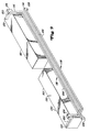
- FIG. 1 shows an embodiment of the present invention in which fluid tank 10 has a filling chamber 12 in fluid connection with a first fluid containment compartment 14 and an opposing second fluid containment compartment 16.
- fluid compartments 14 and 16 are shown as being opposed, it will be recognized that any suitable relation which complies with the concepts and functions herein described may be used.
- the filling chamber 12 includes a filling port 18 in fluid connection with a first fluid passage 20 a second fluid passage 22 and a fluid channel 24.
- the filling chamber 12 may be formed by a plurality of interconnected walls located inside the fluid compartments 14 and 16.
- the filling chamber may be formed in a box-like configuration having two pairs of interconnected opposing side walls with a pair of opposing end walls connected to marginal edges of the two pair of interconnected side walls.
- the first fluid passage 20 may be formed by a filling hole through an end wall 21 of the filling chamber 12 located in the first fluid compartment 14.
- the second fluid passage 22 may be formed by a filling hole through a longitudinally opposed end wall 23 of the filling chamber 12 located in the second fluid compartment 16.
- Any suitable fluid passage may be used including pipes or the like. While filling holes or apertures are used, the sizes of the filling holes may be changed or additional opposing filling holes may be added to increase the fill rate of the tank as shown by supplemental passages 26 and 28.
- the fluid channel 24 is in fluid communication with the first and second fluid passages 20 and 22 as shown by the series of arrows 30 indicating fluid flow during fill up through the fill port 18.
- the fluid channel 24 includes a first orifice 32 proximate one terminal end of the fluid channel 24 and a second orifice 34 proximate another terminal end of the fluid channel 24.
- the first orifice 32 lies below and a lateral distance away from the first fluid passage 20 while the second orifice 34 lies below and laterally distant from the second fluid passage 22.
- the fluid channel 24 may be formed by partition panel 36 having a longitudinal length equal to the longitudinal length of the filling chamber 12 and a transverse width less than the transverse width of the filling chamber 12.
- the partition panel 36 may be latitudinally secured above a floor wall 38 of the filling chamber 12 thereby forming a fluid conduction path between the floor wall 38 and the partition panel 36 and opposing end walls 21 and 23.
- the filling chamber may be formed in any suitable shape and that the fluid passages and fluid channel may be formed to any suitable cross sectional shape and/or cross sectional areas depending on the particular application.
- the fluid channel may be formed in any suitable manner and may be any suitable size or shape.
- the partition panel 36 may be formed to extend the entire transverse width of the channel. Holes may than be drilled at distal ends through the panel to form the fluid channel orifice.
- the connecting section of the fluid channel 24 between the compartments would be unnecessary where multiple compartments shared side walls. For example where compartment 14 and compartment 16 shared a wall W.
- an alternative embodiment may include the filling chamber 12 and corresponding fluid channel 24 extending laterally beyond the surface of the side walls of the compartments 14 and 16.
- the tank 10 also includes pressure equalizing vents 50 for each compartment 14 and 16.
- the vents 50 have an internal channel portion 52 with an opening 54 at one end, and an elbow such as an inverted "U"-shaped continuous channel portion 56 terminated by an opening 58 at another end.
- the internally located channel portion 52 may be positioned transversely and proximate an internal upper longitudinally distal end portion 60 of the compartments 14 and 16 with the elbow portion protruding out of the compartments 14 and 16 to connect with outside air through the opening 58.
- the internal channel portion 52 may be formed by a vent tube 62 latitudinally disposed below a top cover plate 64 of the compartments.
- the length of vent tube 62 may extend less than the transverse width of the compartments and may extend from a side wall 65 of the compartments toward an opposing side wall 66 of the compartments.
- the pressure equalizing vent 50 may be formed by a piece of square tubing extending from walls of the compartments, it will be recognized that any suitable channel forming device may also be used.
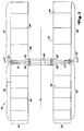
- Fig. 3 shows a tank 70, such as a locomotive fuel tank, with the compartment top cover plates removed.
- the tank 70 includes a filling chamber 72, a first set 74 of two left compartments 76 and 78, and a second set 75 of two right compartments 80 and 82 distributed about a center axis C l such as the longitudinal center axis of a locomotive.
- the filling chamber 72 is substantially similar in design to the filling chamber 24 of Fig. 1, but uses a connecting section 84 made of pipes to allow the sets of compartments 74 and 75 to be located at suitable areas in the locomotive. Similarly, the filling chamber 72 uses passages 88 similar to the passages 20, 22, 26, and 28 described with reference to Fig. 1. Portions of end walls 21 and 23 are angled to allow proper connection of the connection pipes 84 (shown in Fig. 3) between left and right sets of compartments 74 and 75. Dual fill ports 90 and 92 are also arranged in the filling chamber 72 in a similar manner as the filling port 18 described with reference to Fig. 1. However, dual fill ports 90 and 92 allow the tank 70 to be filled from either the left or right side of the locomotive. Each compartment 76, 78, 80, and 82 includes a plurality of upright baffles 94 for preventing "sloshing" and providing additional structural support as known in the art.
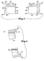
- Fig. 4 illustrates a cross-sectional view of the left side compartment 78, right side compartment 82 and filling chamber 72 shown in Fig. 3.
- Fluid channel orifices 98 and 100 similar to fluid channel orifices 32 and 34 of Fig. 1, are shown proximate side walls 101 and 103, respectively.
- Figs. 5 and 6 will be used to explain the operation of the inventive compartmentalized tank of Fig. 3, however the description applies equally well to the tank of Fig.1.
- the fluid channel 24 facilitates fluid flow between the left and right set of compartments 74 and 75 (seen in Fig. 3) when the tank is being filled and substantially prevents fluid flow between the sets of compartments 74 and 75 when the fluid tank 70 is improperly oriented.
- the fluid loss minimization feature will be discussed in detail later.
- Fig. 5 also shows an upright extending wall section 102 which may be added to the terminal end portion of the partition panel proximate orifices 98 and 100 to add further fluid flow resistance and effectuate a more accurate simultaneous filling of the compartments 76, 78, 80 and 82.
- the distal end of the upright extending wall extends to a position substantially level with the bottom of the fluid passages 88, fluid will not be able to flow directly into the fluid channel 24. Instead, a reservoir formed by the upright section and a side wall portion below the fluid passages 88, must be filled before fluid will simultaneously flow over both the extending wall and through the fluid passages 88.
- the invention applies to tanks divided into two or more compartments, the greater the number of compartments, the smaller the amount of fluid which will be lost in the event of localized tank damage due to an accident.
- Part of this invention is the unique provisions made to allow filling of all compartments simultaneously, without the fill system providing a means of fluid draining from all compartments in the event of damage to one of the compartments.
- the filling chamber 72 in conjunction with a separating wall (not shown) located below the filling chamber 72 divides each of the two sets of left and right compartments 74 and 75 into two compartments 76, 78, 80 and 82, respectively.
- the fluid is pumped into the filling chamber 72 through either or both of the fill ports 90 and 92. Therefore, the fill ports on either side of the tanks can be used to fill all four compartments simultaneously.
- each set of compartments 74 and 75 is provided with two fluid passages 88, located as shown in Fig. 3, the fluid level in the filling chamber 72 will rise until it reaches the bottom of the fluid passages 88 (fill holes). At this time, it will spill over into the compartments 76, 78, 80, and 82 on either side of the filling chamber 72. The result is that all tank compartments will be filled simultaneously, from a single fill point. With the fluid passages 88 located proximate the very top of the filling chamber 72, damage to any tank compartment will not result in fluid transferring from one compartment to the next.
- the fluid passages 88 are located not only at the top of the compartment and filling chamber 72 sides, but also on the innermost point possible on the longitudinal inner wall 85 to the vehicle centerline.
- the fluid passages 88 on the right side compartments will now be oriented at the top of the compartments.
- the fluid passages 88 on the right side of the filling chamber 72 will be at the top of the right side tank compartments 80 and 82, thus minimizing flow between the two right side compartments in the event only one is damaged.
- a purpose of the fluid channel 24 can be seen by looking at Figs. 1, 3, and 5 and the filling chamber portion in the set of left compartments 74.
- the fluid channel 24 prevents fuel from the set of left tank compartments from draining through the connection pipe 84 into the possibly damaged right tank compartments.
- compartment pressure equalizers 50 shielders
- each compartment must be fitted with a pressure equalizer 50 to allow air to exit and enter as the compartments are filled and emptied.
- Fig. 6 shows that in the event the vehicle is on its side, fluid will not have a means of escape through the pressure equalizers 50.
- Figs. 7 and 8 show several ways to connect supply lines to the various compartments for supplying fluid to a fluid employing device, such as a locomotive engine.
- a supply line 104 such as a pipe, extends to the bottom of each compartment.
- the supply lines 104 from all compartments would be connected together, with a valve 106 in each line.
- return lines 110 extend to each compartment and have a valve 106 in each line.
- the valves 106 prevent fluid from improper siphoning from one compartment to the next, which, in the event of a damaged compartment, would otherwise have resulted in all of the fuel siphoning out into the damaged tank.
- the valves 106 may be inside the compartments along with a portion of or entire return or supply line.
- the valves 106 may be any suitable valve, such as a unidirectional check valve, a bidirectional valve, or a remotely controllable valve.
- Fig. 8 shows another embodiment employing a solenoid valve 108 which would be opened to break the vacuum in the lines to prevent siphoning between compartments.
- the solenoid valve 108 could be triggered when the engine shuts down, or by some other means of detection of an accident. Only one valve 108 is used with the main feed line 112 instead of in the individual lines.
- Fig. 9 shows a pair of pressure equalization vents 114 and 116 coupled to two compartments such as compartments 14 and 16 of Fig. 1 or compartments 76, 78, 80, and 82 (all shown without supply lines and return lines) of Fig. 3.
- the vents 114 and 116 are identical to the pressure equalizing vents 50 previously described with reference to Fig. 2 with respect to minimizing fluid loss when the compartments are oriented on their sides.
- the vents 114 and 116 include an additional channel section for also minimizing fluid loss when the compartments are oriented on their ends.
- Each vent 114 and 116 includes a continuous channel 118 made up of interconnected sections.
- the sections include a laterally extending section 120 terminated with an opening 122 at one end, an elbow section 124, and a longitudinally extending section 126 terminated with another opening 128.
- the elbow section 124 such as an inverted "U", section is interposed between the laterally extending section 120 and the longitudinally extending section 126. A portion of the elbow section 124 extends in a generally latitudinal direction to meet the longitudinal section 126.
- the laterally extending section 120 is positioned in the compartment is the same manner as described with reference to the vents 50 of Fig. 2. Consequently, the opening 122 in communication with the inside of the compartment, is located proximate a side wall 130.
- the laterally extending portion 120 has a length less than the lateral width of the compartments and is preferably positioned at a distal end of the compartments and adjacent a top or ceiling wall 132. The laterally extending section 120 extends away from the side wall 130.
- the longitudinally extending section 126 extends away from the laterally extending section 120.
- the longitudinally extending section 126 has a length approximately equal to the longitudinal length of the combined compartments. As shown, the length is slightly greater than the longitudinal length thereby insuring no fluid loss since the opening 128 is above the highest level of the compartment.
- the longitudinally extending section 126 is shown as being external to the compartment, however, it may be located internal to the compartment with the opening 128 allowed to communicate with air where desirable. It will be recognized that the entire channel 118 may be located internal to the tank as long as the opening 128 can communicate with air external to the tank. Thus the pressure equalizing vents 50 of Fig. 1 may also be located completely inside the compartments if the opening 58 can communicate with air.
Landscapes
- Engineering & Computer Science (AREA)
- Mechanical Engineering (AREA)
- Chemical & Material Sciences (AREA)
- Combustion & Propulsion (AREA)
- Transportation (AREA)
- Sustainable Energy (AREA)
- Life Sciences & Earth Sciences (AREA)
- Sustainable Development (AREA)
- General Engineering & Computer Science (AREA)
- Cooling, Air Intake And Gas Exhaust, And Fuel Tank Arrangements In Propulsion Units (AREA)
- Filling Or Discharging Of Gas Storage Vessels (AREA)
- Supply Of Fluid Materials To The Packaging Location (AREA)
- Filling Of Jars Or Cans And Processes For Cleaning And Sealing Jars (AREA)
- Transition And Organic Metals Composition Catalysts For Addition Polymerization (AREA)
Abstract
Claims (10)
- Dispositif (10, 70) formant réservoir de fluide à compartiments, qui comprend :- un premier moyen (14, 74) de confinement du fluide,- un deuxième moyen (16, 75) de confinement du fluide, et- un moyen (12, 72) formant chambre de remplissage, en communication de passage des fluides avec lesdites premier et deuxième moyens (14, 16, 74, 75) de confinement du fluide, servant à remplir lesdits premier et deuxième moyens (14, 16, 74, 75) de confinement du fluide, ledit moyen (12, 72) formant chambre de remplissage ayant une certaine largeur et une certaine longueur et comprenant un premier passage de fluide (20), un deuxième passage de fluide (22) et un canal pour fluide (24),ledit premier passage de fluide (20) facilitant l'écoulement du fluide entre ledit moyen (12, 72) formant chambre de remplissage et ledit premier moyen (14, 74) de confinement du fluide,
ledit deuxième passage de fluide (22) facilitant l'écoulement du fluide entre ledit moyen (12, 72) formant chambre de remplissage et ledit deuxième moyen (16, 75) de confinement du fluide,
ledit canal pour fluide (24) comportant un premier orifice d'extrémité (32) et un deuxième orifice d'extrémité (34), ledit premier orifice d'extrémité (32) étant situé en-dessous dans le sens de la hauteur et à une certaine distance latérale dudit premier passage de fluide (20), ledit deuxième orifice d'extrémité (34) étant situé en-dessous dans le sens de la hauteur et à une certaine distance latérale dudit deuxième passage de fluide (22), ledit canal pour fluide (24) facilitant l'écoulement du fluide entre lesdits premier et deuxième moyens (14, 16, 74, 75) de confinement du fluide quand le réservoir (10, 70) est en cours de remplissage et empêchant sensiblement l'écoulement du fluide entre lesdits premier et deuxième moyens (14, 16, 74, 75) de confinement du fluide quand ledit réservoir (10, 70) n'est pas correctement orienté. - Dispositif selon la revendication 1, dans lequel une partie au moins dudit premier passage de fluide (20) est sensiblement adjacente à une surface supérieure (64) dudit premier moyen (14, 74) de confinement du fluide de sorte que l'écoulement de fluide entre lesdits premier et deuxième moyens (14, 16, 74, 75) de confinement du fluide est limité quand le réservoir (10, 70) s'oriente dans une position indésirable.
- Dispositif selon la revendication 1 ou 2, dans lequel une partie au moins dudit deuxième passage de fluide (22) est sensiblement adjacente à une surface supérieure (64) dudit deuxième moyen (16, 75) de confinement du fluide de sorte que l'écoulement de fluide entre lesdits premier et deuxième moyens (14, 16, 74, 75) de confinement du fluide est limité quand le réservoir (10, 70) s'oriente dans une position indésirable.
- Dispositif selon l'une quelconque des revendications 1 à 3, comprenant en outre des moyens (50, 114, 116) d'égalisation de pression dans chacun desdits premier et deuxième moyens (14, 16, 74, 75) de confinement du fluide, lesdits moyens (50, 114, 116) d'égalisation de pression comprenant un canal (52, 56, 58; 118) servant à conduire un flux d'air dans lesdits moyens (14, 16, 74, 75) de confinement du fluide et hors de ceux-ci, le canal (52, 56, 58; 118) comprenant une première partie de canal (52, 120) d'une longueur inférieure à la largeur desdits moyens (14, 16, 74, 75) de confinement du fluide et comportant un orifice (54, 122) en une première extrémité, ladite première extrémité étant placée à l'intérieur desdits moyens (14, 16, 74, 75) de confinement du fluide, une partie coudée (56, 124) avec une seconde extrémité (58, 128) en communication avec l'air, ladite première partie de canal (52, 120) étant placée transversalement à l'intérieur desdits moyens (14, 16, 74, 75) de confinement du fluide avec ladite première extrémité ouverte (59, 122) située à une certaine distance d'une paroi latérale (66, 130) desdits moyens (14, 16, 74, 75) de confinement du fluide.
- Dispositif selon la revendication 1, dans lequel ledit canal pour fluide (24) a une longueur qui s'étend sur la longueur dudit moyen (12, 72) formant chambre de remplissage et une largeur qui s'étend sur moins que la largeur dudit moyen (12, 72) formant chambre de remplissage.
- Dispositif selon la revendication 1, dans lequel ledit moyen (12) formant chambre de remplissage comporte de multiples tubulures de remplissage (18, 90, 92) pour recevoir du fluide en provenance d'une source de fluide.
- Dispositif selon l'une quelconque des précédentes revendications, comprenant en outre :- un moyen d'alimentation (104) opérationnellement couplé auxdits premier et deuxième moyens (74, 75) de confinement du fluide pour envoyer du fluide desdits premier et deuxième moyens (74, 75) de confinement du fluide à un moyen d'utilisation du fluide, et- un moyen de retour (110) opérationnellement couplé auxdits premier et deuxième moyens (74, 75) de confinement du fluide pour renvoyer du fluide dudit moyen d'utilisation du fluide auxdits premier et deuxième moyens (74, 75) de confinement du fluide.
- Dispositif (10, 70) formant réservoir de fluide à compartiments, qui comprend :- un premier moyen (14, 74) de confinement du fluide,- un deuxième moyen (16, 75) de confinement du fluide, et- un moyen (12, 72) formant chambre de remplissage, en communication de passage des fluides avec lesdites premier et deuxième moyens (14, 16, 74, 75) de confinement du fluide, servant à remplir lesdits premier et deuxième moyens (14, 16, 74, 75) de confinement du fluide, ledit moyen (12, 72) formant chambre de remplissage comprenant une tubulure de remplissage (18, 40, 92) et un moyen (24) formant canal pour fluide, destiné à faciliter l'écoulement du fluide entre lesdits premier et deuxième moyens (14, 16, 74, 75) de confinement du fluide quand le réservoir est en cours de remplissage et à empêcher sensiblement l'écoulement du fluide entre lesdits premier et deuxième moyens (14, 16, 74, 75) de confinement du fluide quand ledit réservoir (10, 70) n'est pas correctement orienté, ledit moyen formant canal pour fluide dans ledit moyen (12, 72) formant chambre de remplissage étant défini par des parois d'extrémité (21, 23) raccordées à une paroi formant fond (38) et une cloison de séparation (36) fixée au-dessus de la paroi formant fond (38) dans ledit moyen formant canal pour fluide et séparant ledit moyen formant canal pour fluide desdits premier et deuxième moyens de confinement du fluide.
- Dispositif selon la revendication 8, comprenant en outre des moyens (50, 114, 116) d'égalisation de pression dans chacun desdits premier et deuxième moyens (14, 16, 74, 75) de confinement du fluide, lesdits moyens (50, 114, 116) d'égalisation de pression comprenant un canal (52, 56) servant à conduire un flux d'air dans lesdits moyens (14, 16, 74, 75) de confinement du fluide et hors de ceux-ci, le canal comprenant une première partie de canal (52, 120) avec une première extrémité (52, 122) placée à l'intérieur desdits moyens (14, 16, 74, 75) de confinement du fluide, et une partie coudée (56, 124) ayant une seconde extrémité (58, 128) en communication avec l'air (58).
- Dispositif selon l'une quelconque des revendications 8 à 9, dans lequel ledit moyen (24) formant canal pour fluide a une longueur qui s'étend sur la longueur dudit moyen (12, 72) formant chambre de remplissage et une largeur qui s'étend sur moins que la largeur dudit moyen (12, 72) formant chambre de remplissage.
Applications Claiming Priority (3)
| Application Number | Priority Date | Filing Date | Title |
|---|---|---|---|
| US881925 | 1992-05-12 | ||
| US07/881,925 US5186352A (en) | 1992-05-12 | 1992-05-12 | Compartmentalized fluid tank |
| PCT/US1993/002691 WO1993023264A1 (fr) | 1992-05-12 | 1993-03-25 | Reservoir a compartiments pour fluides |
Publications (2)
| Publication Number | Publication Date |
|---|---|
| EP0593712A1 EP0593712A1 (fr) | 1994-04-27 |
| EP0593712B1 true EP0593712B1 (fr) | 1997-03-12 |
Family
ID=25379494
Family Applications (1)
| Application Number | Title | Priority Date | Filing Date |
|---|---|---|---|
| EP93909152A Expired - Lifetime EP0593712B1 (fr) | 1992-05-12 | 1993-03-25 | Reservoir a compartiments pour fluides |
Country Status (9)
| Country | Link |
|---|---|
| US (2) | US5186352A (fr) |
| EP (1) | EP0593712B1 (fr) |
| JP (1) | JP3187427B2 (fr) |
| AU (1) | AU659937B2 (fr) |
| BR (1) | BR9305520A (fr) |
| CA (1) | CA2093684C (fr) |
| DE (1) | DE69308721T2 (fr) |
| ES (1) | ES2100531T3 (fr) |
| WO (1) | WO1993023264A1 (fr) |
Families Citing this family (18)
| Publication number | Priority date | Publication date | Assignee | Title |
|---|---|---|---|---|
| US5615768A (en) * | 1994-12-01 | 1997-04-01 | Schermerhorn; David W. | Magnifying holder for a remote control unit |
| US6223526B1 (en) * | 1998-06-17 | 2001-05-01 | Siemens Aktiengesellschaft | Dual compartment fuel storage tank |
| US20030118145A1 (en) * | 2000-05-12 | 2003-06-26 | Faris Sadeg M | Multiple chamber containment system |
| JP2006083809A (ja) * | 2004-09-17 | 2006-03-30 | Yamaha Motor Co Ltd | エンジン駆動式乗り物用オイルタンク |
| FR2901190B1 (fr) * | 2006-05-16 | 2009-01-23 | Inergy Automotive Systems Res | Reservoir liquide et procede pour le fabriquer |
| US8579330B2 (en) * | 2008-11-05 | 2013-11-12 | Colin Gilbert Tobeck | Fluid receiver |
| USD644160S1 (en) * | 2010-06-18 | 2011-08-30 | Cnh America Llc | Auxiliary fuel tank for a vehicle |
| USD644161S1 (en) * | 2010-06-18 | 2011-08-30 | Cnh America Llc | Auxiliary fuel tank for a vehicle |
| US9732714B2 (en) | 2010-08-20 | 2017-08-15 | General Electric Company | Method and system for water drainage in fuel system |
| US9016513B2 (en) * | 2012-11-30 | 2015-04-28 | Caterpillar Inc. | Tank splashguard with multi-tiered labyrinth |
| JP6184756B2 (ja) * | 2013-05-31 | 2017-08-23 | 東日本旅客鉄道株式会社 | 燃料漏れ検知装置 |
| CN103522895A (zh) * | 2013-10-28 | 2014-01-22 | 中国重汽集团济南动力有限公司 | 一种分隔式高安全性油箱 |
| FR3019806B1 (fr) * | 2014-04-10 | 2016-04-01 | Inergy Automotive Systems Res | Reservoir avec canal de ventilation avec couvercle. |
| JP6541568B2 (ja) * | 2015-12-24 | 2019-07-10 | 株式会社クボタ | エンジンを搭載した作業車両 |
| CN105883246B (zh) * | 2016-06-01 | 2019-03-26 | 中国恩菲工程技术有限公司 | 具有自消能结构溢流管的矿浆贮槽 |
| CN109533358A (zh) * | 2018-11-06 | 2019-03-29 | 珠海隆华直升机科技有限公司 | 直升机内置油箱及直升机 |
| JP2023013735A (ja) * | 2021-07-16 | 2023-01-26 | ヤマハ発動機株式会社 | 燃料マネジメントシステム |
| GB2639030A (en) * | 2024-03-07 | 2025-09-10 | Terex Gb Ltd | Hydraulic tank |
Family Cites Families (12)
| Publication number | Priority date | Publication date | Assignee | Title |
|---|---|---|---|---|
| GB599594A (en) * | 1945-09-21 | 1948-03-16 | Mahlon Charles Snyder | Improvements in means for storing liquid fuel |
| US2794569A (en) * | 1954-02-24 | 1957-06-04 | Arrow Mfg & Sales Co Inc | Compartmented saddle tank |
| US3552596A (en) * | 1968-09-09 | 1971-01-05 | James E Landon | Gas tank |
| US3615999A (en) * | 1969-04-03 | 1971-10-26 | Rech Et De Commercialisation D | Method of constructing compartmented tankers |
| US3931907A (en) * | 1975-01-15 | 1976-01-13 | Henle George A | Combination water supply and waste holding tank |
| JPS5820445Y2 (ja) * | 1977-07-30 | 1983-04-27 | アイシン精機株式会社 | マスタシリンダリザ−バ |
| US4224110A (en) * | 1977-12-05 | 1980-09-23 | Mccord James W | Cleaning device |
| US4298130A (en) * | 1980-08-18 | 1981-11-03 | Abraham Ifrach | Anti-theft motor fuel tank |
| US4511105A (en) * | 1982-01-13 | 1985-04-16 | The United States Of America As Represented By The Secretary Of The Air Force | Compartmented, filament wound, one-piece aircraft fuel tanks |
| FI854653A7 (fi) * | 1985-11-25 | 1987-05-26 | Tarmo Koskinen | Kuljetussäiliö bulk-tavaran kuljetusta varten. |
| US4809860A (en) * | 1987-12-07 | 1989-03-07 | Mark L. Anderson | Aspiration container assembly for collecting follicular fluids |
| DE4116349A1 (de) * | 1991-05-18 | 1992-11-19 | Daimler Benz Ag | Kraftstoffbehaelter |
-
1992
- 1992-05-12 US US07/881,925 patent/US5186352A/en not_active Expired - Lifetime
-
1993
- 1993-01-06 US US08/001,011 patent/US5305908A/en not_active Expired - Fee Related
- 1993-03-25 ES ES93909152T patent/ES2100531T3/es not_active Expired - Lifetime
- 1993-03-25 AU AU39666/93A patent/AU659937B2/en not_active Expired
- 1993-03-25 JP JP52020093A patent/JP3187427B2/ja not_active Expired - Lifetime
- 1993-03-25 BR BR9305520A patent/BR9305520A/pt not_active IP Right Cessation
- 1993-03-25 WO PCT/US1993/002691 patent/WO1993023264A1/fr not_active Ceased
- 1993-03-25 EP EP93909152A patent/EP0593712B1/fr not_active Expired - Lifetime
- 1993-03-25 DE DE69308721T patent/DE69308721T2/de not_active Expired - Lifetime
- 1993-04-08 CA CA002093684A patent/CA2093684C/fr not_active Expired - Lifetime
Also Published As
| Publication number | Publication date |
|---|---|
| BR9305520A (pt) | 1995-03-01 |
| ES2100531T3 (es) | 1997-06-16 |
| AU659937B2 (en) | 1995-06-01 |
| US5305908A (en) | 1994-04-26 |
| WO1993023264A1 (fr) | 1993-11-25 |
| US5186352A (en) | 1993-02-16 |
| EP0593712A1 (fr) | 1994-04-27 |
| JP3187427B2 (ja) | 2001-07-11 |
| CA2093684A1 (fr) | 1993-11-13 |
| DE69308721T2 (de) | 1997-10-30 |
| JPH06509304A (ja) | 1994-10-20 |
| AU3966693A (en) | 1993-12-13 |
| DE69308721D1 (de) | 1997-04-17 |
| CA2093684C (fr) | 2005-11-08 |
Similar Documents
| Publication | Publication Date | Title |
|---|---|---|
| EP0593712B1 (fr) | Reservoir a compartiments pour fluides | |
| US4210176A (en) | Hydraulic liquid reservoir with internal baffle | |
| US4930537A (en) | Vehicle multiple-tank fuel system | |
| US5360034A (en) | Dual fuel tank system | |
| CA2237515C (fr) | Systeme de ventilation du reservoir a carburant pour vehicule | |
| JP4173365B2 (ja) | 燃料タンク | |
| US11035286B2 (en) | Coolant reservoir tank | |
| US4531653A (en) | Ventilation device for fuel tanks | |
| US4765359A (en) | Filling manifold for plural fuel tanks | |
| US6425379B2 (en) | Evaporative emission control system | |
| US20080256948A1 (en) | Reservoir and master cylinder | |
| US6659122B1 (en) | Dual tank simultaneous fill system | |
| US4441520A (en) | Hydraulic fluid reservoir system | |
| US10906391B2 (en) | Fuel tank having inlet check valve | |
| US5829619A (en) | Adapter for motor vehicle fuel filler pipes | |
| US6491030B2 (en) | Ventilation device for a fuel tank | |
| US4241578A (en) | Fluid storage tank for an industrial vehicle | |
| WO1997038871A1 (fr) | Structure de tuyau d'admission | |
| EP0042214B1 (fr) | Réservoir à liquide arrangé pour limiter l'égouttage indésirable | |
| CA3047673C (fr) | Reservoir de combustible et methodes | |
| CN216610858U (zh) | 低地板车型油箱通气结构 | |
| JPH02176155A (ja) | 車両用燃料タンクの燃料流出防止装置 | |
| JPH058184Y2 (fr) | ||
| JPH0338137B2 (fr) | ||
| KR890004398Y1 (ko) | 자동차 브레이크 안전장치 |
Legal Events
| Date | Code | Title | Description |
|---|---|---|---|
| PUAI | Public reference made under article 153(3) epc to a published international application that has entered the european phase |
Free format text: ORIGINAL CODE: 0009012 |
|
| 17P | Request for examination filed |
Effective date: 19940111 |
|
| AK | Designated contracting states |
Kind code of ref document: A1 Designated state(s): DE ES FR GB IT |
|
| 17Q | First examination report despatched |
Effective date: 19950125 |
|
| GRAG | Despatch of communication of intention to grant |
Free format text: ORIGINAL CODE: EPIDOS AGRA |
|
| GRAH | Despatch of communication of intention to grant a patent |
Free format text: ORIGINAL CODE: EPIDOS IGRA |
|
| GRAH | Despatch of communication of intention to grant a patent |
Free format text: ORIGINAL CODE: EPIDOS IGRA |
|
| GRAA | (expected) grant |
Free format text: ORIGINAL CODE: 0009210 |
|
| AK | Designated contracting states |
Kind code of ref document: B1 Designated state(s): DE ES FR GB IT |
|
| ET | Fr: translation filed | ||
| REF | Corresponds to: |
Ref document number: 69308721 Country of ref document: DE Date of ref document: 19970417 |
|
| ITF | It: translation for a ep patent filed | ||
| REG | Reference to a national code |
Ref country code: ES Ref legal event code: FG2A Ref document number: 2100531 Country of ref document: ES Kind code of ref document: T3 |
|
| PLBE | No opposition filed within time limit |
Free format text: ORIGINAL CODE: 0009261 |
|
| STAA | Information on the status of an ep patent application or granted ep patent |
Free format text: STATUS: NO OPPOSITION FILED WITHIN TIME LIMIT |
|
| 26N | No opposition filed | ||
| REG | Reference to a national code |
Ref country code: GB Ref legal event code: IF02 |
|
| PGFP | Annual fee paid to national office [announced via postgrant information from national office to epo] |
Ref country code: FR Payment date: 20120406 Year of fee payment: 20 |
|
| PGFP | Annual fee paid to national office [announced via postgrant information from national office to epo] |
Ref country code: IT Payment date: 20120327 Year of fee payment: 20 Ref country code: GB Payment date: 20120326 Year of fee payment: 20 |
|
| PGFP | Annual fee paid to national office [announced via postgrant information from national office to epo] |
Ref country code: DE Payment date: 20120328 Year of fee payment: 20 |
|
| REG | Reference to a national code |
Ref country code: DE Ref legal event code: R071 Ref document number: 69308721 Country of ref document: DE |
|
| REG | Reference to a national code |
Ref country code: GB Ref legal event code: PE20 Expiry date: 20130324 |
|
| PG25 | Lapsed in a contracting state [announced via postgrant information from national office to epo] |
Ref country code: DE Free format text: LAPSE BECAUSE OF EXPIRATION OF PROTECTION Effective date: 20130326 Ref country code: GB Free format text: LAPSE BECAUSE OF EXPIRATION OF PROTECTION Effective date: 20130324 |
|
| PGFP | Annual fee paid to national office [announced via postgrant information from national office to epo] |
Ref country code: ES Payment date: 20120326 Year of fee payment: 20 |
|
| REG | Reference to a national code |
Ref country code: ES Ref legal event code: FD2A Effective date: 20130718 |
|
| PG25 | Lapsed in a contracting state [announced via postgrant information from national office to epo] |
Ref country code: ES Free format text: LAPSE BECAUSE OF EXPIRATION OF PROTECTION Effective date: 20130326 |