EP0593730B1 - Selbstbe- und entladener hochbordiger güterwagen - Google Patents
Selbstbe- und entladener hochbordiger güterwagen Download PDFInfo
- Publication number
- EP0593730B1 EP0593730B1 EP93910131A EP93910131A EP0593730B1 EP 0593730 B1 EP0593730 B1 EP 0593730B1 EP 93910131 A EP93910131 A EP 93910131A EP 93910131 A EP93910131 A EP 93910131A EP 0593730 B1 EP0593730 B1 EP 0593730B1
- Authority
- EP
- European Patent Office
- Prior art keywords
- conveyor
- truck according
- buckets
- chain
- endless chain
- Prior art date
- Legal status (The legal status is an assumption and is not a legal conclusion. Google has not performed a legal analysis and makes no representation as to the accuracy of the status listed.)
- Expired - Lifetime
Links
- 239000000463 material Substances 0.000 claims description 40
- 230000000630 rising effect Effects 0.000 claims 3
- 239000013590 bulk material Substances 0.000 abstract 4
- 230000001174 ascending effect Effects 0.000 description 10
- 239000002699 waste material Substances 0.000 description 10
- 238000007789 sealing Methods 0.000 description 4
- 230000009471 action Effects 0.000 description 3
- 230000007246 mechanism Effects 0.000 description 2
- 230000009747 swallowing Effects 0.000 description 2
- 230000007704 transition Effects 0.000 description 2
- 241001125843 Trichiuridae Species 0.000 description 1
- 238000009825 accumulation Methods 0.000 description 1
- 230000015556 catabolic process Effects 0.000 description 1
- 230000001066 destructive effect Effects 0.000 description 1
- 238000007598 dipping method Methods 0.000 description 1
- 230000000694 effects Effects 0.000 description 1
- 230000003028 elevating effect Effects 0.000 description 1
- 238000009432 framing Methods 0.000 description 1
- 230000005484 gravity Effects 0.000 description 1
- 230000008439 repair process Effects 0.000 description 1
- 230000000284 resting effect Effects 0.000 description 1
- 239000004576 sand Substances 0.000 description 1
- 238000012216 screening Methods 0.000 description 1
Images


Classifications
-
- B—PERFORMING OPERATIONS; TRANSPORTING
- B61—RAILWAYS
- B61D—BODY DETAILS OR KINDS OF RAILWAY VEHICLES
- B61D15/00—Other railway vehicles, e.g. scaffold cars; Adaptations of vehicles for use on railways
-
- E—FIXED CONSTRUCTIONS
- E01—CONSTRUCTION OF ROADS, RAILWAYS, OR BRIDGES
- E01B—PERMANENT WAY; PERMANENT-WAY TOOLS; MACHINES FOR MAKING RAILWAYS OF ALL KINDS
- E01B27/00—Placing, renewing, working, cleaning, or taking-up the ballast, with or without concurrent work on the track; Devices therefor; Packing sleepers
- E01B27/06—Renewing or cleaning the ballast in situ, with or without concurrent work on the track
Definitions
- the invention relates to a self-loading and self-unloading dump wagon equipped with a high-walled crate and a system for loading and unloading bulk materials comprising a general conveyor for transporting at least bulk materials from one front wall to the other of the body.
- This type of dump wagon is commonly used to transport bulk materials such as waste extracted from railway lining materials.
- This waste is evacuated from the railway after a screening operation and transported in dump cars to be deposited in landfill areas.
- a stripping operation a large amount of waste is taken from the track.
- the stripping machine is coupled to a convoy of dump cars, each dump car having a capacity of about 30 cubic meters. During a day of stripping the tracks, several convoys of dump cars loaded with waste are unloaded.
- the dump cars are self-loading.
- a belt conveyor system generally arranged in cascade is used, each gondola wagon having its own conveyor. The dump cars are thus loaded one after the other, starting with the leading dump car.
- the oblique conveyor is oriented transversely to ensure the unloading of materials on the ground, next to the track, it will not be able to meet the conditions of height (4 meters) and distance (6 meters) which are generally imposed for the discharge of materials by this conveyor. Indeed, it has a large width, equal to that of the wagon body; it is therefore heavy. On the other hand, it should be given a great length to reach the prescribed height at its discharge end, since its other end must be at the bottom of the boxes. A wagon fitted with such a conveyor would not comply with the limit load distribution condition 40% / 60% relating to the respective load of the two wheels on the same axle when this conveyor is oriented towards the side of the wagon.
- the object of the invention is to remedy these various drawbacks.
- the invention relates to a dump wagon of the kind defined at the start, in which, according to the invention, the general conveyor is arranged at an average level close to that of the upper edges of the body and the loading system. and unloading further comprises a handling device capable of reloading on the general conveyor the bulk materials deposited in the box.
- the general conveyor which ensures the transport of materials along a train of dump wagons to be loaded, is no longer located at the bottom of the wagon body, but in the upper part.
- this conveyor and with it the waste stream that it carries, is removed from the action of the mass of waste contained in the box that it overcomes, and it is easily accessible at all times for repair. possible.
- it may have a reduced width, therefore a light structure.
- this general conveyor comprises a directional unloading conveyor on the side, the latter can easily meet the conditions mentioned above. Indeed, because of its low weight and the situation in height of its starting point, and no longer at the bottom of the body, it can easily convey the materials higher and further.
- the handling device preferably comprises bodies for picking up bulk materials circulating in a plane transverse to the longitudinal direction of the box and of the general conveyor, the handling device being able to move further in translation between the walls front of the body.
- the endless chain is preferably a double chain framing the buckets and its guide means consist of a pair of parallel rails, carried by the frame, which guide the endless chain at least along its lower and ascending parts.
- these comprise, on the inside of the loop path of the endless chain, a movable wall formed by an articulated cover, while means are provided for controlling the position of this cover , who maintain it in the closed position in the lower and ascending parts of said loop path and allow its opening in the upper part of the latter, thus allowing the buckets to empty their contents when they overhang the general conveyor.
- the means for controlling the position of the bucket cover may be constituted by the guide rails of the endless chain, which for this purpose have a U-shaped section and face each other by their longitudinal openings, one of the wings of these rails being wide enough to marginally cover the cover, while it narrows at the top of the loop path so as to release the cover, allowing it to tip into the open position.
- the buckets offer, on the inside of the loop path of the endless chain, an open face, devoid of wall, which is closed, in the ascending part and a portion of the upper part of their path , by a strip running parallel to the bucket chain, at the same speed and in the same direction, the buckets applying by their open face against said strip, until they leave it in the upper part of their path, then pouring their contents onto the general conveyor.
- the buckets should be coupled to the endless chain via a single hinge pin located near their mouth, around which they can pivot, relative to the endless chain and in the mean plane of its path, of a small angle of deflection defined by means of limitation of tilting associated with each bucket.
- the path of the closure band of the buckets preferably continues over a portion of the upper part of the path of the bucket chain, this portion having a length such that the buckets pour their contents into the central zone of the conveyor.
- a fixed support plate can be provided, against which the obturating strip leans in the portion of its path where the buckets are applied to it.
- the general conveyor with which the wagon is equipped it advantageously comprises a first conveyor belt extending substantially horizontally between the front walls of the box, and a second conveyor belt mounted on an orientable and tilting boom, which can be oriented longitudinally to extend the first to a wagon adjacent to the convoy or transversely to one side of the track.
- the advantages provided by the invention essentially consist in that it makes it possible to produce wagons with automatic loading and unloading thanks to a handling device specific to each wagon, any wagon in a convoy which can be loaded and unloaded by direct access.
- the handling device adapts directly to a dump wagon without modifying its structure, while the general conveyor of each wagon can be replaced, if necessary, even when the wagon is loaded.
- the general conveyor that the general conveyor can include, it is possible to unload a wagon by bringing the materials it contains to a dumping point on the side of the track, located at a height and at a distance from the track suitable for meeting the standards applicable to railway networks.
- FIG. 1 represents a part of a convoy of dump wagons equipped with a loading and unloading system according to the invention.
- FIG. 2 represents, schematically and on a larger scale, the mobile lifting device of one of the dump wagons of FIG. 1.
- Figure 3 is a cross-sectional view, also on an enlarged scale, of a dump wagon fitted with equipment according to the invention according to a first embodiment.
- Figures 4 and 5 schematically show, in perspective, respectively a portion of the lower part and a portion of the upper part of the bucket chain of the mobile elevator.
- FIG. 6 represents, in the manner of FIG. 3, a second embodiment of a dump wagon equipment according to the invention.
- Figures 7 to 9 schematically show, respectively in perspective, in vertical section and in elevation, a portion of the lower part, a portion of the upper part and a portion of the ascending part of the bucket chain of the mobile elevator of Figure 6.
- FIG. 10 represents a section along line XX of the object of FIG. 9.
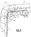
- Figure 11 is an enlarged schematic view of the portion of the bucket chain of Figure 6 located at the transition between the ascending part and the upper part.
- FIG. 1 a self-loading and self-unloading dump wagon, coupled to another identical dump wagon but visible only in part.
- These dump wagons comprise a plate 13 on which is fixed a box 1 having high walls, namely two front walls 2 and two side walls 3.
- This type of dump wagon is used for the transport of bulk materials, in particular during operations. stripping of railways.
- the dump car shown is equipped with a system for loading and unloading bulk materials according to the invention.
- This system comprises a general conveyor 4 which makes it possible to convey bulk materials, supplied by a stripping machine or by the general conveyor of another dump wagon harnessed to the right of the wagon in question, from the front wall 2 of the body located on the right in the figure towards the other front wall 2 of the body located on the left in the figure.
- the general conveyor 4 comprises a first conveyor 6 equipped with a band circulating horizontally between end rollers 16 and a second conveyor 7 with a band carried by an arrow 8.
- the arrow 8 can pivot at its end 10 on the platform 13 of the wagon, which allows it to be oriented at will to direct its other end on one side or the other of the railroad tracks or above the conveyor 6 of another wagon, as shown.
- a jack 11 articulated to the arrow 8 and to the plate 13 of the wagon also makes it possible to adjust the inclination of the latter.
- the end 10 of the boom further carries a hopper 12 into which the materials conveyed by the conveyor 6 belonging to the same wagon are discharged.
- a stand 14 fixed to the arrow 8 allows it to bear on the next wagon, for example on the energy group 15 carried by this wagon.
- the first conveyor 6 which is used for loading the box 1 is arranged substantially horizontally above the front walls 2 of the box and rests on the upper edges thereof by means of elements support not shown.
- the conveyor 6 is therefore located above the box and can be dismantled even when the box 1 is loaded with bulk materials.
- the materials conveyed by the conveyor 6 are guided on the strip 18 of the latter between two edges constituted by successive pivoting gates 9 whose approximation in V makes it possible to direct the flow of materials in the box at the desired locations.
- the loading and unloading system also includes an elevating handling device 5 capable of recharging the bulk materials deposited in the box on the belt 18 of the conveyor 6 which then routes them to the oblique conveyor 7.
- the handling device 5 can be moved in the longitudinal direction of the body from one front wall to the other thereof, so that it allows, in cooperation with the general conveyor 4, to completely unload the body 1 of the gondola wagon.
- the handling device 5 comprises a frame 51 extending transversely with respect to the longitudinal axis of the body 1 and having two ends 52 which rest on the upper edges of the walls lateral 3 of the body 1 by means of sets of rollers 80 which allow the movements in translation of the frame between the two front walls 2 of the body.
- This frame comprises a pair of upper arches 51a which pass over the first conveyor 6, and a pair of lower arches 51b which pass under the first conveyor 6.
- These pairs of arches support a pair of front members and rear 64 which extend transversely and descend vertically in the body 1.
- endless 54 with buckets 55 guided along a closed path extending in a transverse plane with respect to the longitudinal direction of the box 1 and surrounding the conveyor 6. It is a double chain, the buckets 55 being mounted in succession between its two parts, the guidance of which is provided by a pair of rails 53 carried by the frame 51 of the handling device 5, each having the shape of a frame.
- the two guide rails 53 surround the conveyor 6 and plunge inside the box 1 along the walls side 3 and the bottom 13 of the body.
- the guide rails have a U-shaped section and are arranged face to face, their longitudinal openings being opposite ( Figures 4 and 5).
- Each of the two parts of the double chain 54 circulates in a respective one of these guide rails, between their wings 53a, 53b, under the action of a geared motor 58 mounted on the frame 51 and attacking one at less than two pairs of sprockets 59a, 59b on which the endless double chain 54 meshes.
- the direction of movement of the bucket chain is identified by the arrows C.
- These sprockets are arranged in the upper part of the frames formed by the rails 53 so as not to be in contact with the materials deposited in the body 1.
- the circuit of the chain 54 is such that the buckets 55 fill in the bottom of the box and empty once they have arrived above the belt 18 of the conveyor 6.
- each bucket 55 is provided, on its face turned downwards when it is in the upper part of its path, with an opening wall 60 which can pivot around a hinge pin 61.
- This wall is kept closed on the major part of the chain circuit 54 by the inner wings 53b of the rails 53, to which a larger width has been given for this purpose than with the outer wings 53a.
- the inner wings 53b are narrowed to provide notches 90 allowing the opening of the wall 60 of each bucket at this location, as can be seen in FIGS. 3 and 5.
- Each cup 55 has for its filling a mouth 62 in the shape of a trapezoid.
- the side walls of the bucket form with the fixed wall which connects them facing the opening wall 60 an angle of attack 63 playing the role of a knife which allows, whatever the direction of movement of the frame 51, to disaggregate the materials in bulk by swallowing them at the base of the embankment formed by the natural accumulation of materials spilled into the body when loading the wagon ( Figure 2).
- the endless chain 54 fitted with its buckets 55 can raise bulk materials from the bottom of the box onto the belt 18 of the conveyor 6 independently of the direction of progression of the frame 51 along the box.
- the conveyor 6 carries along its longitudinal edges a pair of flanges 41 dipping inside the body and arranged on either side of the chain 57, of so as to protect it from the materials falling into the box 1 during loading operations.
- the conveyor 6 is provided, along its longitudinal edges, deflectors 42 which direct the materials conveyed by the conveyor 6 towards the lateral edges 3 of the box.
- Another set of deflectors 43 can be provided on the handling device 5 to channel the materials discharged by each bucket 55 onto the belt 18 of the conveyor 6, one of these deflectors having the role of helping to close the articulated wall 60 of the bucket.
- handling device 5 must be replaced, in the event of a breakdown for example, it suffices for this to slide the conveyor 6 in one direction or the other according to the arrow R or A, using a crane, to release the frame 51. This can be done even when the wagon is loaded with loose materials.
- FIG. 6 Another embodiment of the handling device 5 is shown in Figure 6. Its general structure is similar to that of the device described above.
- the collection and lifting of the materials in the box 1 of the wagon is always done using a double chain 54 with buckets circulating around the conveyor 6 and plunging to the bottom 13 of the box.
- the buckets now designated by the reference 155, are, for emptying, devoid of the opening wall 60 that comprise the buckets 55 of the previous example. They are in fact open on the corresponding face, as can be seen by comparing FIGS. 4 and 7.
- a sealing strip 70 is provided there, which moves parallel to the chain 54, in the same direction and with the same speed (FIG.
- this strip being disposed at a distance from the chain 54 such that the buckets are applied to it by the whole of their open face, which thus closed, the strip being slightly wider than the open face of the cups ( Figure 10).
- a sole 71 is provided, which stands parallel to the path of the chain and along which the strip 70 moves by sliding. This silk 71 also constitutes a sealing element having the role of preventing the materials from entering behind the strip 70.
- the buckets 155 on the obturating strip 70 are connected to the chain 54 by articulation along a single axis 72 located near their mouth 62, around which they can pivot relative to the chain, on an angle limited by a pair of rods 73 articulated to the double chain 54, each being engaged by a buttonhole 74 on a lug 75 secured to the corresponding side wall of each bucket.
- the arrangement is such that the weight P of the cup 155 and its contents, applied at its center of gravity G, creates a torque which tends to keep the cup applied on the sealing strip, so that it moves in a can with it, its open face remaining perfectly closed over the entire ascending part of the endless chain 54.
- the strip 70 extends a little beyond the top of this part, still supported by the sole 71 oriented here substantially horizontally, so as to maintain the closure of the open face of the buckets 155 until they arrive in good position above the conveyor 6 to pour their contents there. If, in this portion of the upper part of the path of the bucket chain, these were not perfectly closed by the strip 70, the materials which could escape therefrom would be collected by the latter and would likewise be found dumped into the conveyor at the point where the strip 70 ends its race by passing over a deflection roller 76.
- This roller 76 is also the drive roller which circulates the strip 70.
- On its shaft 77 (FIG. 11) is in fact wedged a pinion 78 coupled in rotation by a chain 79 to a pinion 81 wedged on the shaft 82 of the pair of sprockets 59a for driving the double chain 54, these sprockets being situated at the transition between the ascending and upper parts of the path of the latter.
- On this same shaft actuated in rotation by the geared motor 58, turns a drum 83 on which the strip 70 is supported (FIG. 8).
- the ratio of the diameters of the pinions 78 and 81 is calculated, as a function of the diameters of the pinions 59a and of the drum 76, so that the sealing strip moves at exactly the same linear speed as the bucket chain.
- the strip 70 passes over a deflection roller 84 which turns idly around an axis distinct from that of the pair of neighboring sprockets 59c which ensures the deflection at this point of the chain. with buckets.
- a fourth pair of idler sprockets 59d is likewise provided at the start of the lower part of the path of the bucket chain. It will be noted that, in this embodiment, the rails 54 for guiding the latter do not cover its entire path, but are limited to the lower and ascending parts thereof, as shown in FIG. 6.
Landscapes
- Engineering & Computer Science (AREA)
- Transportation (AREA)
- Mechanical Engineering (AREA)
- Architecture (AREA)
- Civil Engineering (AREA)
- Structural Engineering (AREA)
- Loading Or Unloading Of Vehicles (AREA)
- Chain Conveyers (AREA)
- Handcart (AREA)
- Vertical, Hearth, Or Arc Furnaces (AREA)
- Control Of Position, Course, Altitude, Or Attitude Of Moving Bodies (AREA)
- Vehicle Body Suspensions (AREA)
Claims (16)
- Selbstladender und selbstentladender offener, hochbordiger Güterwagen, der mit einem Kasten (1) mit hohen Wänden (2, 3) und einem Belade- und Entladesystem für loses Material ausgerüstet ist, das aus einem Hauptförderer (4) zum Befördern des losen Materials mindestens von einer Stirnwand (2) des Kastens zur anderen besteht,
dadurch gekennzeichnet, daß der Hauptförderer in einer mittleren Höhe im Bereich der Höhe der Oberkanten des Kastens (1) angeordnet ist, und daß das Belade- und Entladesystem ferner eine Transportvorrichtung (5) umfaßt, die geeignet ist, das in dem Kasten befindliche lose Material auf den Hauptförderer nachzuladen. - Güterwagen nach Anspruch 1,
dadurch gekennzeichnet, daß die Transportvorrichtung (5) Organe (55, 155) zum Einsammeln von losem Material umfaßt, die in einer Ebene quer zur Längsrichtung des Kastens (1) und des Hauptförderers (4) kreisen, wobei die Transportvorrichtung sich ferner zwischen den Stirnwänden (2) des Kastens in einer Vorschubbewegung verschieben kann. - Güterwagen nach Anspruch 2,
dadurch gekennzeichnet, daß die Transportvorrichtung (5) umfaßt:- ein verfahrbares Gestell (51), das mit seinen Enden (52) auf den Oberkanten der Seitenwände (3) des Kastens (1) aufliegt,- eine umlaufende Kette (54) mit Baggerkübeln (55, 155), die mittels Antriebsmitteln auf einer schleifenförmigen Strecke läuft, die durch mit dem verfahrbaren Gestell (51) verbundene Führungsmittel definiert ist, um den Hauptförderer (4) herumführt und in das Innere des Kastens (1) eintaucht, wobei sie an dessen Seitenwänden (3) und Boden (13) entlangführt, und- Mittel zum Verschieben des verfahrbaren Gestells (51) zwischen den Stirnwänden (2) des Kastens. - Güterwagen nach Anspruch 3,
dadurch gekennzeichnet, daß die umlaufende Kette (54) eine Doppelkette ist, die die Baggerkübel (55, 155) einfaßt, und daß ihre Führungsmittel aus einem Paar parallel laufender, an dem Gestell (51) angebrachter Schienen (53) bestehen, die die umlaufende Kette mindestens an ihren unteren und ansteigenden Abschnitten entlang führen. - Güterwagen nach einem der Ansprüche 1 bis 4,
dadurch gekennzeichnet, daß die Baggerkübel (55) an der Innenseite der schleifenförmigen Strecke der umlaufenden Kette (54) eine bewegliche Wand (60) aufweisen, die aus einem angelenkten Deckel besteht, und daß Steuermittel für die Stellung dieses Deckels vorgesehen sind, die ihn während des unteren und ansteigenden Abschnitts der genannten schleifenförmigen Strecke in Schließstellung halten und in ihrem oberen Abschnitt sein Öffnen zulassen, wodurch sie es ermöglichen, daß die Baggerkübel ihren Inhalt ausschütten, wenn sie sich über dem Hauptförderer befinden. - Güterwagen nach den Ansprüchen 4 und 5,
dadurch gekennzeichnet, daß die Steuermittel für die Stellung des Deckels (60) der Baggerkübel (55) von den Führungsschienen (53) der umlaufenden Kette (54) gebildet werden, die einen U-förmigen Querschnitt haben und mit ihren Längsöffnungen einander zugewandt sind, wobei der eine Flügel dieser Schienen ausreichend breit ist, um den Deckel am Rand abzudecken, während er im oberen Abschnitt der schleifenförmigen Strecke schmaler wird, so daß er den Deckel freigibt und ihm damit die Kippbewegung in die geöffnete Stellung gestattet. - Güterwagen nach einem der Ansprüche 1 bis 4,
dadurch gekennzeichnet, daß die Baggerkübel (155) an der Innenseite der schleifenförmigen Strecke der umlaufenden Kette (54) eine offene Seite ohne Wand aufweisen, die während des ansteigenden Abschnitts und eines Teils des oberen Abschnitts ihrer Strecke durch ein Band (70) verschlossen wird, das parallel zu der Baggerkübel-Kette mit der gleichen Geschwindigkeit und in der gleichen Richtung umläuft, wobei die Baggerkübel sich mit ihrer offenen Seite an das genannte Band pressen, bis sie es in dem oberen Abschnitt ihrer Strecke verlassen und dabei ihren Inhalt auf den Hauptförderer auskippen. - Güterwagen nach Anspruch 7,
dadurch gekennzeichnet, daß die Baggerkübel (155) an der umlaufenden Kette über eine einzige Gelenkachse (72) angekuppelt ist, die sich nahe bei ihrer Öffnung (62) befindet und um die sie gegenüber der umlaufenden Kette und in der Ebene ihrer Strecke um einen kleinen Winkel kippen können, dessen Ausschlag durch Kippbegrenzungsmittel in Verbindung mit jedem Baggerkübel bestimmt ist. - Güterwagen nach Anspruch 7 oder 8,
dadurch gekennzeichnet, daß die Strecke des Bandes (72) zum Verschließen der Baggerkübel auf einem Teil des oberen Abschnitts der Strecke der Baggerkübel-Kette fortgesetzt wird, wobei dieser Abschnitt eine Länge solcherart hat, daß die Baggerkübel ihren Inhalt in den zentralen Bereich des Hauptförderers kippen. - Güterwagen nach einem der Ansprüche 7 bis 9,
dadurch gekennzeichnet, daß das Verschließband (70) in dem Abschnitt seiner Strecke, in dem sich die Baggerkübel dagegen pressen, an einer feststehenden Stützplatte (71) Halt findet. - Güterwagen nach einem der Ansprüche 3 bis 10,
dadurch gekennzeichnet, daß die Antriebsmittel der umlaufenden Kette (54) aus einem Getriebemotor (58) bestehen, der mindestens ein an dem Gestell (51) angebrachtes Ritzel (59a) antreibt, mit dem die umlaufenden Kette in Eingriff ist. - Güterwagen nach einem der Ansprüche 3 bis 11,
dadurch gekennzeichnet, daß die Verfahrmittel des Gestells (51) aus einer an dem Gestell (51) angebrachten Winde (56) bestehen, die eine zwischen den Stirnwänden (2) des Kastens gespannte Kette (57) in der einen oder der anderen Richtung ziehen kann. - Güterwagen nach Anspruch 12,
dadurch gekennzeichnet, daß der Hauptförderer (4) ein Paar Scheiben (41) aufweist, die ins Innere des Kastens eintauchen und zu beiden Seiten der zwischen den Stirnwänden (2) des Kastens gespannte Kette (57) angeordnet sind. - Güterwagen nach einem der Ansprüche 3 bis 13,
dadurch gekennzeichnet, daß die Enden (52) des Gestells (51) mit Laufrollen (80) versehen sind, die auf den Oberkanten der Seitenwände (3) des Kastens ruhen. - Güterwagen nach einem der Ansprüche 3 bis 14,
dadurch gekennzeichnet, daß jeder Baggerkübel (55, 155) eine trapezförmige Einfüllöffnung (62) aufweist, mit der aufgrund ihres Ansatzwinkels (63) das lose Material bei jeder Verfahrrichtung des Gestells (51) getrennt werden kann. - Güterwagen nach einem der vorherigen Ansprüche,
dadurch gekennzeichnet, daß der Hauptförderer (4) einen ersten Bandförderer (6), der sich zwischen den Stirnwänden (2) des Kastens im wesentlichen waagerecht erstreckt, und einen Zweiten Bandförderer (7), der auf einem Ausleger angebracht ist, der gedreht und geneigt werden kann, umfaßt, wobei der zweite Bandförderer in Längsrichtung ausgerichtet werden kann, um den ersten zu einem angrenzenden Güterwagen des Zuges hin oder in Querrichtung zu einer Seite des Gleises hin zu verlängern.
Applications Claiming Priority (3)
| Application Number | Priority Date | Filing Date | Title |
|---|---|---|---|
| FR9206065A FR2691420B1 (fr) | 1992-05-19 | 1992-05-19 | Wagon tombereau autochargeable et dechargeable. |
| FR9206065 | 1992-05-19 | ||
| PCT/FR1993/000479 WO1993023276A1 (fr) | 1992-05-19 | 1993-05-18 | Wagon tombereau auto-chargeable et auto-dechargeable |
Publications (2)
| Publication Number | Publication Date |
|---|---|
| EP0593730A1 EP0593730A1 (de) | 1994-04-27 |
| EP0593730B1 true EP0593730B1 (de) | 1995-09-27 |
Family
ID=9429930
Family Applications (1)
| Application Number | Title | Priority Date | Filing Date |
|---|---|---|---|
| EP93910131A Expired - Lifetime EP0593730B1 (de) | 1992-05-19 | 1993-05-18 | Selbstbe- und entladener hochbordiger güterwagen |
Country Status (6)
| Country | Link |
|---|---|
| EP (1) | EP0593730B1 (de) |
| AT (1) | ATE128421T1 (de) |
| AU (1) | AU5173393A (de) |
| DE (1) | DE69300556T2 (de) |
| FR (1) | FR2691420B1 (de) |
| WO (1) | WO1993023276A1 (de) |
Families Citing this family (3)
| Publication number | Priority date | Publication date | Assignee | Title |
|---|---|---|---|---|
| CZ279535B6 (cs) * | 1993-05-07 | 1995-05-17 | Franz Plasser Bahnbaumaschinen-Industriegesellschaft M.B.H. | Nákladní vůz pro přepravu a ukládání sypkého materiálu |
| FR2762821B1 (fr) * | 1997-05-02 | 2001-02-09 | Ddl Sa | Dispositif de manutention de charges en vrac contenues dans un wagon |
| ITMI20111485A1 (it) * | 2011-08-03 | 2013-02-04 | Sistemi Ferroviari S R L | Container, carro da trasporto ferroviario utilizzante tale container e procedimento per il carico/scarico di inerti da un carro da trasporto ferroviario |
Family Cites Families (2)
| Publication number | Priority date | Publication date | Assignee | Title |
|---|---|---|---|---|
| US3167193A (en) * | 1962-05-14 | 1965-01-26 | Klosk Lawrence | Loading car with conveyor |
| DE2403010A1 (de) * | 1974-01-23 | 1975-07-31 | Wieger Maschbau | Vorrichtung zum be- und entladen von aufnahmewagen |
-
1992
- 1992-05-19 FR FR9206065A patent/FR2691420B1/fr not_active Expired - Fee Related
-
1993
- 1993-05-18 EP EP93910131A patent/EP0593730B1/de not_active Expired - Lifetime
- 1993-05-18 WO PCT/FR1993/000479 patent/WO1993023276A1/fr not_active Ceased
- 1993-05-18 AU AU51733/93A patent/AU5173393A/en not_active Abandoned
- 1993-05-18 AT AT93910131T patent/ATE128421T1/de not_active IP Right Cessation
- 1993-05-18 DE DE69300556T patent/DE69300556T2/de not_active Expired - Fee Related
Also Published As
| Publication number | Publication date |
|---|---|
| DE69300556T2 (de) | 1996-05-15 |
| AU5173393A (en) | 1993-12-13 |
| FR2691420A1 (fr) | 1993-11-26 |
| WO1993023276A1 (fr) | 1993-11-25 |
| ATE128421T1 (de) | 1995-10-15 |
| EP0593730A1 (de) | 1994-04-27 |
| DE69300556D1 (de) | 1995-11-02 |
| FR2691420B1 (fr) | 1995-06-16 |
Similar Documents
| Publication | Publication Date | Title |
|---|---|---|
| FR2533520A1 (fr) | Wagon de chargement de matiere deversable, en particulier pour le chargement de deblais provenant d'une machine d'epuration de lit de ballast | |
| FR2487394A1 (fr) | Installation mobile pour l'assainissement du soutenement des voies ferrees et procede d'assainissement obtenu avec une telle installation | |
| FR2510531A1 (fr) | Appareil de manutention et de recuperation de matiere en vrac | |
| FR2519924A1 (fr) | Installation deplacable sur rails pour le transport de deblais | |
| EP2497684A1 (de) | Transportanhänger zum Abladen über ein Förderband | |
| EP0593730B1 (de) | Selbstbe- und entladener hochbordiger güterwagen | |
| FR2461664A1 (fr) | Conteneur a dechets avec moyens de supportage et de manutention | |
| WO2013144489A1 (fr) | Wagon de transport de granulats double flux | |
| FR2668785A1 (fr) | Machine pour la collecte et l'emmagasinage continus de moyens de fixation de rail detaches. | |
| FR2924701A1 (fr) | Installation de chargement de produits divises dans des bennes | |
| EP0608190B1 (de) | Trichter zum Laden von Schüttgütern | |
| CZ31592A3 (en) | set for catching and transportation of ballast, waste or another loose material | |
| FR2685307A1 (fr) | Dispositif de transport continu de matieres en vrac. | |
| FR2557864A1 (fr) | Systeme de transport pour le chargement et le dechargement de navires | |
| FR2666003A1 (fr) | Procede, dispositif et machine pour recolter mecaniquement des baies. | |
| FR2864053A1 (fr) | Vehicule de transport d'objets en vrac et installation de transport | |
| FR2460603A1 (fr) | Chariot pour le chargement automatique de balles de fourrage | |
| EP0654424A1 (de) | Zusammengesetzter Bausatz zum getrennten Sammeln und Transportieren von Müll | |
| FR2931173A1 (fr) | Benne montee sur un chassis mobile et destinee a contenir des materiaux en vrac | |
| CH84371A (fr) | Appareil élévateur transporteur | |
| FR2587981A1 (fr) | Dispositif modulaire de manutention et de stockage de materiaux en vrac | |
| FR2780709A1 (fr) | Perfectionnement d'un dispositif de transfert automatique du chargement d'une tremie dans la benne d'un camion automobile | |
| FR2595671A1 (fr) | Dispositif de transfert des deblais d'un chariot excavateur a une bande transporteuse | |
| BE891731A (fr) | Train de chargement et transport, notamment pour le deblaiement de tunnel, et son procede de mise en oeuvre | |
| FR2577861A1 (fr) | Machine a distribuer les caisses-palettes |
Legal Events
| Date | Code | Title | Description |
|---|---|---|---|
| PUAI | Public reference made under article 153(3) epc to a published international application that has entered the european phase |
Free format text: ORIGINAL CODE: 0009012 |
|
| 17P | Request for examination filed |
Effective date: 19940117 |
|
| AK | Designated contracting states |
Kind code of ref document: A1 Designated state(s): AT CH DE ES FR GB IT LI NL SE |
|
| 17Q | First examination report despatched |
Effective date: 19941125 |
|
| GRAA | (expected) grant |
Free format text: ORIGINAL CODE: 0009210 |
|
| AK | Designated contracting states |
Kind code of ref document: B1 Designated state(s): AT CH DE ES FR GB IT LI NL SE |
|
| PG25 | Lapsed in a contracting state [announced via postgrant information from national office to epo] |
Ref country code: NL Free format text: LAPSE BECAUSE OF FAILURE TO SUBMIT A TRANSLATION OF THE DESCRIPTION OR TO PAY THE FEE WITHIN THE PRESCRIBED TIME-LIMIT Effective date: 19950927 Ref country code: IT Free format text: LAPSE BECAUSE OF FAILURE TO SUBMIT A TRANSLATION OF THE DESCRIPTION OR TO PAY THE FEE WITHIN THE PRE;WARNING: LAPSES OF ITALIAN PATENTS WITH EFFECTIVE DATE BEFORE 2007 MAY HAVE OCCURRED AT ANY TIME BEFORE 2007. THE CORRECT EFFECTIVE DATE MAY BE DIFFERENT FROM THE ONE RECORDED.SCRIBED TIME-LIMIT Effective date: 19950927 Ref country code: GB Effective date: 19950927 Ref country code: ES Free format text: THE PATENT HAS BEEN ANNULLED BY A DECISION OF A NATIONAL AUTHORITY Effective date: 19950927 |
|
| REF | Corresponds to: |
Ref document number: 128421 Country of ref document: AT Date of ref document: 19951015 Kind code of ref document: T |
|
| REF | Corresponds to: |
Ref document number: 69300556 Country of ref document: DE Date of ref document: 19951102 |
|
| PG25 | Lapsed in a contracting state [announced via postgrant information from national office to epo] |
Ref country code: SE Effective date: 19951227 |
|
| REG | Reference to a national code |
Ref country code: CH Ref legal event code: NV Representative=s name: BOVARD AG PATENTANWAELTE |
|
| NLV1 | Nl: lapsed or annulled due to failure to fulfill the requirements of art. 29p and 29m of the patents act | ||
| GBV | Gb: ep patent (uk) treated as always having been void in accordance with gb section 77(7)/1977 [no translation filed] |
Effective date: 19950927 |
|
| PLBE | No opposition filed within time limit |
Free format text: ORIGINAL CODE: 0009261 |
|
| STAA | Information on the status of an ep patent application or granted ep patent |
Free format text: STATUS: NO OPPOSITION FILED WITHIN TIME LIMIT |
|
| 26N | No opposition filed | ||
| PGFP | Annual fee paid to national office [announced via postgrant information from national office to epo] |
Ref country code: AT Payment date: 19980424 Year of fee payment: 6 |
|
| PGFP | Annual fee paid to national office [announced via postgrant information from national office to epo] |
Ref country code: DE Payment date: 19980519 Year of fee payment: 6 |
|
| PGFP | Annual fee paid to national office [announced via postgrant information from national office to epo] |
Ref country code: CH Payment date: 19980520 Year of fee payment: 6 |
|
| PG25 | Lapsed in a contracting state [announced via postgrant information from national office to epo] |
Ref country code: AT Free format text: LAPSE BECAUSE OF NON-PAYMENT OF DUE FEES Effective date: 19990518 |
|
| PG25 | Lapsed in a contracting state [announced via postgrant information from national office to epo] |
Ref country code: LI Free format text: LAPSE BECAUSE OF NON-PAYMENT OF DUE FEES Effective date: 19990531 Ref country code: CH Free format text: LAPSE BECAUSE OF NON-PAYMENT OF DUE FEES Effective date: 19990531 |
|
| REG | Reference to a national code |
Ref country code: CH Ref legal event code: PL |
|
| PG25 | Lapsed in a contracting state [announced via postgrant information from national office to epo] |
Ref country code: DE Free format text: LAPSE BECAUSE OF NON-PAYMENT OF DUE FEES Effective date: 20000301 |
|
| PGFP | Annual fee paid to national office [announced via postgrant information from national office to epo] |
Ref country code: FR Payment date: 20040525 Year of fee payment: 12 |
|
| PG25 | Lapsed in a contracting state [announced via postgrant information from national office to epo] |
Ref country code: FR Free format text: LAPSE BECAUSE OF NON-PAYMENT OF DUE FEES Effective date: 20060131 |
|
| REG | Reference to a national code |
Ref country code: FR Ref legal event code: ST Effective date: 20060131 |