EP0593799A1 - Procédé et dispositif pour façonner un flan en tôle - Google Patents
Procédé et dispositif pour façonner un flan en tôle Download PDFInfo
- Publication number
- EP0593799A1 EP0593799A1 EP92117831A EP92117831A EP0593799A1 EP 0593799 A1 EP0593799 A1 EP 0593799A1 EP 92117831 A EP92117831 A EP 92117831A EP 92117831 A EP92117831 A EP 92117831A EP 0593799 A1 EP0593799 A1 EP 0593799A1
- Authority
- EP
- European Patent Office
- Prior art keywords
- pressure rollers
- metal blank
- workpiece
- sheet metal
- control
- Prior art date
- Legal status (The legal status is an assumption and is not a legal conclusion. Google has not performed a legal analysis and makes no representation as to the accuracy of the status listed.)
- Granted
Links
- 238000000034 method Methods 0.000 title claims abstract description 25
- 238000007493 shaping process Methods 0.000 title description 2
- 239000000463 material Substances 0.000 claims abstract description 26
- 239000002184 metal Substances 0.000 claims abstract description 23
- 229910052751 metal Inorganic materials 0.000 claims abstract description 23
- 230000033001 locomotion Effects 0.000 claims description 12
- 229910045601 alloy Inorganic materials 0.000 claims description 9
- 239000000956 alloy Substances 0.000 claims description 9
- 230000002093 peripheral effect Effects 0.000 claims 1
- 238000009987 spinning Methods 0.000 abstract description 6
- 238000010438 heat treatment Methods 0.000 description 5
- 238000000137 annealing Methods 0.000 description 3
- 238000010586 diagram Methods 0.000 description 3
- 239000010936 titanium Substances 0.000 description 3
- 229910001069 Ti alloy Inorganic materials 0.000 description 2
- RTAQQCXQSZGOHL-UHFFFAOYSA-N Titanium Chemical compound [Ti] RTAQQCXQSZGOHL-UHFFFAOYSA-N 0.000 description 2
- 239000000969 carrier Substances 0.000 description 2
- 230000007797 corrosion Effects 0.000 description 2
- 238000005260 corrosion Methods 0.000 description 2
- 238000011161 development Methods 0.000 description 2
- 230000018109 developmental process Effects 0.000 description 2
- 239000007789 gas Substances 0.000 description 2
- 230000001681 protective effect Effects 0.000 description 2
- 238000005482 strain hardening Methods 0.000 description 2
- 229910052719 titanium Inorganic materials 0.000 description 2
- UFHFLCQGNIYNRP-UHFFFAOYSA-N Hydrogen Chemical compound [H][H] UFHFLCQGNIYNRP-UHFFFAOYSA-N 0.000 description 1
- 238000010521 absorption reaction Methods 0.000 description 1
- 238000005097 cold rolling Methods 0.000 description 1
- 238000005520 cutting process Methods 0.000 description 1
- 230000007547 defect Effects 0.000 description 1
- 238000006073 displacement reaction Methods 0.000 description 1
- 230000000694 effects Effects 0.000 description 1
- 239000002828 fuel tank Substances 0.000 description 1
- 239000001257 hydrogen Substances 0.000 description 1
- 229910052739 hydrogen Inorganic materials 0.000 description 1
- 230000001939 inductive effect Effects 0.000 description 1
- 238000003754 machining Methods 0.000 description 1
- 238000004519 manufacturing process Methods 0.000 description 1
- 230000004048 modification Effects 0.000 description 1
- 238000012986 modification Methods 0.000 description 1
- 238000005096 rolling process Methods 0.000 description 1
- 239000007787 solid Substances 0.000 description 1
- 239000007858 starting material Substances 0.000 description 1
- 238000009864 tensile test Methods 0.000 description 1
- 230000007704 transition Effects 0.000 description 1
Images

Classifications
-
- B—PERFORMING OPERATIONS; TRANSPORTING
- B21—MECHANICAL METAL-WORKING WITHOUT ESSENTIALLY REMOVING MATERIAL; PUNCHING METAL
- B21D—WORKING OR PROCESSING OF SHEET METAL OR METAL TUBES, RODS OR PROFILES WITHOUT ESSENTIALLY REMOVING MATERIAL; PUNCHING METAL
- B21D22/00—Shaping without cutting, by stamping, spinning, or deep-drawing
- B21D22/14—Spinning
- B21D22/18—Spinning using tools guided to produce the required profile
Definitions
- the invention relates to a method for deforming a sheet metal blank from a material with an exponential tensile stress-strain behavior and a device suitable for carrying out this method.
- titanium and its alloys are increasingly used for fuel tanks or the like because of their low weight and good corrosion resistance.
- the titanium- ⁇ alloys that are particularly suitable for this purpose are insufficiently cold-formable.
- These alloys have an exponential stress-strain behavior, as is illustrated by a schematic stress-strain diagram in FIG. 1.
- the diagram shows that the titanium- ⁇ alloys do not have the usual work hardening, so that when the tensile test is carried out below room temperature above the yield point, in the plastic range, the necking and then breaking takes place without any further increase in tensile stress. This has a major impact on the cold formability of these materials.
- shells with a larger diameter (over 600 mm), a small wall thickness (under 3 mm) and / or a high curvature (hemisphere) have so far only been produced by hot-forming processes, after which the desired small wall thickness had to be removed by machining.
- titanium and its alloys have a high affinity for air components, which on the one hand form a corrosion layer on the surface of the material and on the other hand make the material brittle due to hydrogen absorption. Both are highly undesirable and can only be prevented or eliminated if either the heating (for hot forming or heat treatment) takes place in a protective gas atmosphere or the corroded layer is removed mechanically or the embrittlement is reversed by heat treatment.
- the invention has for its object to provide a simple and inexpensive method and a device for cold forming a material with exponential tensile stress-strain behavior to hollow shells of low wall thickness.
- the high degree of cold forming that can be achieved with the method according to the invention brings about a grain refinement in the structure of the titanium- ⁇ alloy, which in turn results in higher strength and toughness, so that the load-bearing cross section and thus the weight can be further reduced.
- the high degree of cold deformation in the circumferential direction leads to a change in the texture of the original rolling direction of the cold-rolled sheet metal blank, so that the risk of inherent stress distortion associated with this texture is reduced.
- the pressure forces to be applied via the pressure rollers can be metered very precisely, so that not only shells with a constant wall thickness but also wall thickness changing over the circumference of the shell can be easily produced.
- the springback that occurs when sheet metal is arched can be controlled so precisely that the shells can be manufactured with a very high degree of dimensional accuracy. Since neither a protective gas atmosphere nor repeated intermediate annealing are necessary, the process according to the invention can be carried out simply and quickly.
- the object is further achieved by a device according to claim 5.
- the workpiece is rotated and the spinning rollers are driven in a path-controlled manner.
- This division of the relative movements helps to prevent tensile stresses in the plastic area during the deformation.
- US-PS 3 815 395 it is already known to form tank bottoms with the aid of two pressure rollers acting on opposite sides of the workpiece, but in the device described there the workpiece is clamped in the center and freely rotatable, while the pressure rollers are both driven in rotation as well as over a predetermined radial path (which causes the workpiece to rotate).
- This superimposition of the motion control means that local tensile stresses cannot be avoided.
- the device is therefore only usable either for hot forming or for materials with normal work hardening.
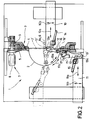
- the sheet metal blank 2 shows a device 1 for cold forming sheet metal blanks 2 '(shown in dashed lines) into hollow shells 2 which, in addition to the hemispherical shape shown, can also be shaped as a spherical cap, conical, elliptical or with other cross-sectional shapes.
- the sheet metal blank 2 ' is in the form of a sheet metal blank made of a material with the exponential tensile stress-strain characteristic shown in FIG. 1. These materials include the titanium-beta alloys Ti-15V-3Cr-3Al-3Sn (Ti15-3) and Ti-3Al-15Mo-2.7Nb-0.2Si (Beta-21S).
- the sheet thickness of the blank 2 ' is normally above the desired sheet thickness of the finished shell, but can already have final dimensions in certain areas (near the opening, pole). If the finished shell 2 is to have larger wall thickness differences, it may be advisable to contour the sheet metal blank beforehand with different raw wall thicknesses, e.g. by turning or grinding.
- the diameter of the sheet metal blank 2 ' is selected in accordance with the desired opening width of the finished shell plus the clamping dimension. With the present method, shells with an opening width of over 600 mm can be produced, which previously could not be produced by cold forming. Even opening widths of 1500 or 2500mm and above are possible.
- the method according to the invention is preferably used for thin-walled shells with wall thicknesses between 0.3 and 3 mm.
- the sheet metal blank 2 ' is held in the device 1 by a clamping device 3, which has a clamping ring 4 for uniformly clamping the circumference of the sheet metal blank 2 '.
- the clamping device 3 is optionally adjustable in order to allow the clamping of blanks 2 'with different diameters.
- the clamping ring 4 is rotatably mounted about a center line 6 in the direction of arrow 6a via a rotary bearing 5 designed as a roller bearing. The rotation is carried out by a drive 7, which has a motor 8 and a drive pinion 9, which meshes with a correspondingly formed toothing on the clamping ring 4.
- Each of the tool carriers 10, 11 is parallel to the center line 6 in a first direction in the direction of the double arrows 10a and 11a, and in a direction in the direction of the double arrows 10b and 11b in a second direction linearly displaceable perpendicular to the center line 6.
- the direction of movement 10a and 10b or 11a and 11b lie in one plane.
- an arm 12 or 13 can be rotated about an axis 12 'or 13' in the direction of the double arrows 12a or 13a.
- the axes 12 'and 13' are perpendicular to the plane of movement of the linear displacements 10a, 10b and 11a, 11b, so that the twisting movement 12a, 13a takes place in the plane of the linear movements 10a, 10b and 11a, 11b.
- a suitable actuator 14 or 15 is provided for pivoting the arms 12 and 13 in the direction of the double arrows 12a, 13a, which simultaneously applies the deformation force.
- each arm 12, 13 there is one Press roller 16, 17 freely rotatable about an axis 16 'or 17'.
- the axes 16 'and 17' extend perpendicular to the pivot axis 12 'and 13' of the respective arm 12, 13 and are arranged such that each of the pressure rollers 16, 17 projects with its circumference over the respective arm 12, 13 and with the above part of its circumference can be brought into contact with the workpiece 2 ', 2.
- the pressure rollers 16, 17 are also arranged in the direction of rotation of the workpiece 2 ', 2, so that they can be rotated about their axes 16', 17 'by the rotating workpiece.
- the first, on the inside of the curvature to be produced pressure roller 16 is relatively narrow and provided with a rounded circumference, so that even with narrow curvatures, only the circumference of the first pressure roller 16 comes into contact with the workpiece 2 ', 2.
- the second pressure roller 17 arranged on the outside of the curvature to be produced is designed as a counter roller against which the first pressure roller 16 works.
- the drive of the clamping device 3, the actuators 14 and 15 and the drives, not shown, for moving the tool carriers 10, 11 in the directions 10a, 10b or 11a, 11b are connected to a common control, also not shown.
- the controller can be a CNC controller, a template copy controller, or any other known controller.
- the pressure rollers 16 and 17 are guided synchronously during the forming process, so that both pressure rollers 16, 17 always work against each other at the location of the deformation.
- Both pressure rollers 16, 17 are thereby moved by a combined linear movement along the double arrows 10a, 10b or 11a, 11b and a pivoting movement along the double arrows 12a, 13a each controlled in the direction of their axes 16 ', 17' via a path along the double arrows 16a and 17a, which follows the contour of the curvature to be formed in this deformation step.
- the tracks 16a and 17a of the pressure rollers 16 and 17 extend radially to the sheet metal blank 2 'or over a meridian of the curvature, the common plane in which the tracks 16a and 17a lie intersecting the center line 6.
- the direction of the deformation takes place from the area near the clamping ring 4 to the point of intersection of the center line 6 through the workpiece 2 ', 2 at the pole and back, the rollers 16, 17 in the solid position in Fig. 2 near a turning point of the Path control and in the position shown in dashed lines near the other reversal point of the path control.
- the path control is carried out in such a way that the two pressure rollers 16, 17 can pivot relative to one another only about the center of the curvature of their circumferential surfaces (radius R) in order not to generate any frictional forces.
- the control further effects a feed movement of the pressure roller 16 in the direction of the counter roller 17 and away from it, in order to adjust the distance between the two pressure rollers 16 and 17 to the wall thicknesses of the workpiece 2 ', 2 which decrease in the course of the deformation process.
- This feed movement can take place during the shaping process and can be controlled, for example, by pressure sensors on the pressure rollers.
- a predetermined control of the roller spacing is also possible if areas of the workpiece 2 ', 2 are to be deformed to different degrees, for example to provide the shells 2 with different wall thicknesses.
- the device 1 operates as follows: after the sheet metal blank 2 'has been clamped in, the clamping ring 4 is rotated by the drive 7 about the center line 6 in the direction of the arrow 6a. Then the pressure rollers 16 and 17 are brought to the blank 2 'at a predetermined distance from one another from opposite sides and are guided radially to the blank 2' in a path 16a and 17a, respectively, which is predetermined for the first deformation step, so that in connection with the rotation of the blank 2 'results in a spiral line around the center line 6.
- the speed of the clamping ring 4, the distance between the pressure rollers 16, 17 and the shape and speed of the path control in the direction of arrows 16a and 17a are so matched to one another and to the material used that the pressure rollers 16 and 17 alone compressive forces to deform the material are exerted, while any tensile forces that remain may remain below the yield strength of the material and thus make no contribution to plastic deformation.
- the material is thus merely squeezed between the pressure rollers 16 and 17, the material being allowed to elongate essentially perpendicular to the direction of the pressure forces.
- the path control of the pressure rollers 16, 17 ensures that this material elongation does not lead to bulging, but rather forms the desired curvature without the material having to be stretched by tensile stresses, as in conventional pressure methods.
- a tank half-shell was formed from the titanium alloy Ti 15-3 using the method according to the invention.
- a sheet blank with a diameter of 510mm was cut from a cold-rolled sheet in solution-annealed and with a cutting roller machine quenched condition, sheet thickness 2.08mm, cut out.
- the sheet metal blank was formed with the help of two pressure rollers using pressure forces in 28 forming steps without intermediate annealing to a hemispherical shell with an opening diameter of 444.8mm, an unchanged wall thickness of 2.08mm directly at the pole, a wall thickness of 2mm at an angular distance of about 5 ° to the pole, a wall thickness of 1.32 mm directly adjacent to the clamping point at the shell opening and a wall thickness curve that continuously drops between the shell opening and the pole to about 0.76 mm and then rises again continuously. No fatigue cracks or shape discontinuities such as folds or bumps were found in the finished tank half-shell.
- a tank half-shell with an opening diameter of 950mm was also manufactured.
- a pre-contoured sheet blank was used as the starting material, the sheet thickness of which was 3.2 mm near its center and 2.1 mm in the remaining outer edge area. The transition between the two wall thickness areas was rounded out. The contouring was carried out using grinding or turning processes specially developed for titanium alloys.
- This pre-contoured sheet metal blank was cold-formed into a tank half-shell with an opening diameter of 950 mm using the method according to the invention and without intermediate annealing.
- the material in the pole area of the shell was also deformed and thus stretched, so that the wall thickness in the pole was reduced to 3.0 mm.
- the wall thickness in the opening area of the bowl was 1.2 mm.
- the wall thickness initially narrowed to 0.8 mm and then rose again continuously.
- the change in thickness of the pre-contoured sheet blank was compensated somewhat, but was still visible.
- This tank half-shell also showed neither fatigue cracks nor shape discontinuities such as folds or bumps after the deformation.
- the pressure rollers can also be moved linearly only in two axes if larger manufacturing tolerances are permitted.
- the shape and size of the spinning rollers can be changed according to the work to be done. Both pressure rollers can have the same shape. Under certain circumstances, a preformed blank can also be used instead of the sheet metal blank.
Landscapes
- Engineering & Computer Science (AREA)
- Mechanical Engineering (AREA)
- Shaping Metal By Deep-Drawing, Or The Like (AREA)
Priority Applications (4)
| Application Number | Priority Date | Filing Date | Title |
|---|---|---|---|
| DE59204955T DE59204955D1 (de) | 1992-10-19 | 1992-10-19 | Verfahren und Vorrichtung zum Verformen eines Blechrohlings |
| EP92117831A EP0593799B1 (fr) | 1992-10-19 | 1992-10-19 | Procédé et dispositif pour façonner un flan en tÔle |
| US08/136,335 US5426964A (en) | 1992-10-19 | 1993-10-13 | Method & apparatus for shaping a sheet blank |
| JP5261183A JP2942121B2 (ja) | 1992-10-19 | 1993-10-19 | シートブランクを成形加工するための方法および装置 |
Applications Claiming Priority (1)
| Application Number | Priority Date | Filing Date | Title |
|---|---|---|---|
| EP92117831A EP0593799B1 (fr) | 1992-10-19 | 1992-10-19 | Procédé et dispositif pour façonner un flan en tÔle |
Publications (2)
| Publication Number | Publication Date |
|---|---|
| EP0593799A1 true EP0593799A1 (fr) | 1994-04-27 |
| EP0593799B1 EP0593799B1 (fr) | 1996-01-03 |
Family
ID=8210148
Family Applications (1)
| Application Number | Title | Priority Date | Filing Date |
|---|---|---|---|
| EP92117831A Expired - Lifetime EP0593799B1 (fr) | 1992-10-19 | 1992-10-19 | Procédé et dispositif pour façonner un flan en tÔle |
Country Status (4)
| Country | Link |
|---|---|
| US (1) | US5426964A (fr) |
| EP (1) | EP0593799B1 (fr) |
| JP (1) | JP2942121B2 (fr) |
| DE (1) | DE59204955D1 (fr) |
Cited By (3)
| Publication number | Priority date | Publication date | Assignee | Title |
|---|---|---|---|---|
| CN105382073A (zh) * | 2010-10-01 | 2016-03-09 | 剑桥企业有限公司 | 旋压成形工艺及用于通过旋压成形来制造物品的装置 |
| CN112108552A (zh) * | 2020-08-27 | 2020-12-22 | 吴守尧 | 一种用于机械加工的旋压装置 |
| CN112496135A (zh) * | 2020-12-18 | 2021-03-16 | 航天特种材料及工艺技术研究所 | 三旋轮数控旋压机的力平衡控制方法 |
Families Citing this family (14)
| Publication number | Priority date | Publication date | Assignee | Title |
|---|---|---|---|---|
| EP1189711B1 (fr) * | 1999-05-05 | 2004-07-14 | Standex International Corporation | Procede de fabrication d'un dome a partir d'un flan sous-dimensionne |
| PT1469957E (pt) * | 2002-01-17 | 2008-11-28 | Quide B V | Método e máquina de conformação para fabrico de um produto com vários diâmetros |
| DE10316854A1 (de) * | 2003-04-11 | 2004-10-21 | Erich Sieger | Verfahren und Vorrichtung zum Verformen eines Werkstücks aus einem Werkstoff mit exponentiellem Zuspannungs-Dehnungsverhalten zu einer dünnwandigen, hohlen Schale |
| DE102005024627A1 (de) | 2005-05-30 | 2006-12-07 | Mt Aerospace Ag | Vakuumgestütztes Verfahren und Vorrichtung zum Umformen eines im Wesentlichen flächigen Rohlings aus Metall zu einem dünnwandigen Schalenkörper sowie deren Verwendung |
| US8561283B1 (en) * | 2007-10-29 | 2013-10-22 | Prestolite Performance, Llc | Method to provide a universal bellhousing between an engine and transmission of a vehicle |
| US20120186936A1 (en) | 2011-01-26 | 2012-07-26 | Prestolite Performance Llc. | Clutch assembly cover, method of making same, and optional heat management |
| US9482308B2 (en) | 2011-01-26 | 2016-11-01 | Accel Performance Group Llc | Automotive flywheel with fins to increase airflow through clutch, method of making same, and heat management method |
| FR2983424B1 (fr) * | 2011-12-02 | 2014-09-19 | Nantes Ecole Centrale | Procede et dispositif d'usinage par addition de matiere et mise en forme combinees |
| US9545932B1 (en) * | 2014-02-11 | 2017-01-17 | Samuel, Son & Co., Limited | Cold-formed tank head for railroad tank car |
| CN104275378B (zh) * | 2014-10-24 | 2016-09-28 | 中南大学 | 大径厚比大弓高比封头冲旋成型装置及冲旋方法 |
| US10502306B1 (en) | 2016-04-25 | 2019-12-10 | Accel Performance Group Llc | Bellhousing alignment device and method |
| US10318904B2 (en) | 2016-05-06 | 2019-06-11 | General Electric Company | Computing system to control the use of physical state attainment of assets to meet temporal performance criteria |
| GB2591275B (en) * | 2020-01-23 | 2022-06-08 | Nissan Motor Mfg Uk Ltd | Method of controlling a mandrel-free spinning apparatus |
| CN119281917B (zh) * | 2024-12-13 | 2025-04-22 | 新乡县四达封头有限公司 | 一种封头旋压成型设备 |
Citations (4)
| Publication number | Priority date | Publication date | Assignee | Title |
|---|---|---|---|---|
| US3342051A (en) * | 1964-08-10 | 1967-09-19 | Leszak Edward | Apparatus and process for incremental dieless forming |
| DE1527973A1 (de) * | 1965-02-08 | 1969-09-04 | Gen Electric | Verfahren zur Herstellung von Rotationsflaechen |
| US3815395A (en) | 1971-09-29 | 1974-06-11 | Ottensener Eisenwerk Gmbh | Method and device for heating and flanging circular discs |
| EP0457358A2 (fr) * | 1990-05-18 | 1991-11-21 | ZEPPELIN-Metallwerke GmbH | Procédé et dispositif de fluotournage |
Family Cites Families (3)
| Publication number | Priority date | Publication date | Assignee | Title |
|---|---|---|---|---|
| US3248918A (en) * | 1963-09-20 | 1966-05-03 | Decibel Prod | Method for forming reflectors |
| JPS5134381B2 (fr) * | 1971-08-11 | 1976-09-25 | ||
| US4134284A (en) * | 1977-06-01 | 1979-01-16 | Achim Nitschke | Method and apparatus for the manufacture of hollow bodies |
-
1992
- 1992-10-19 EP EP92117831A patent/EP0593799B1/fr not_active Expired - Lifetime
- 1992-10-19 DE DE59204955T patent/DE59204955D1/de not_active Expired - Lifetime
-
1993
- 1993-10-13 US US08/136,335 patent/US5426964A/en not_active Expired - Lifetime
- 1993-10-19 JP JP5261183A patent/JP2942121B2/ja not_active Expired - Lifetime
Patent Citations (4)
| Publication number | Priority date | Publication date | Assignee | Title |
|---|---|---|---|---|
| US3342051A (en) * | 1964-08-10 | 1967-09-19 | Leszak Edward | Apparatus and process for incremental dieless forming |
| DE1527973A1 (de) * | 1965-02-08 | 1969-09-04 | Gen Electric | Verfahren zur Herstellung von Rotationsflaechen |
| US3815395A (en) | 1971-09-29 | 1974-06-11 | Ottensener Eisenwerk Gmbh | Method and device for heating and flanging circular discs |
| EP0457358A2 (fr) * | 1990-05-18 | 1991-11-21 | ZEPPELIN-Metallwerke GmbH | Procédé et dispositif de fluotournage |
Cited By (3)
| Publication number | Priority date | Publication date | Assignee | Title |
|---|---|---|---|---|
| CN105382073A (zh) * | 2010-10-01 | 2016-03-09 | 剑桥企业有限公司 | 旋压成形工艺及用于通过旋压成形来制造物品的装置 |
| CN112108552A (zh) * | 2020-08-27 | 2020-12-22 | 吴守尧 | 一种用于机械加工的旋压装置 |
| CN112496135A (zh) * | 2020-12-18 | 2021-03-16 | 航天特种材料及工艺技术研究所 | 三旋轮数控旋压机的力平衡控制方法 |
Also Published As
| Publication number | Publication date |
|---|---|
| EP0593799B1 (fr) | 1996-01-03 |
| DE59204955D1 (de) | 1996-02-15 |
| JP2942121B2 (ja) | 1999-08-30 |
| JPH06210362A (ja) | 1994-08-02 |
| US5426964A (en) | 1995-06-27 |
Similar Documents
| Publication | Publication Date | Title |
|---|---|---|
| EP0593799B1 (fr) | Procédé et dispositif pour façonner un flan en tÔle | |
| EP1651366A1 (fr) | PROCEDE ET DISPOSITIF PERMETTANT DE FAçONNER UNE PIECE CONSTITUEE D'UN MATERIAU PRESENTANT UN COMPORTEMENT A LA CONTRAINTE DE TRACTION-ALLONGEMENT DE TYPE EXPONENTIEL POUR OBTENIR UNE ENVELOPPE CREUSE A PAROI MINCE | |
| EP1481744B1 (fr) | Procédé et dispositif pour fabriquer une pièce profilée | |
| DE102021117777B3 (de) | Verfahren und Vorrichtung zur Herstellung eines Wälzlagerkäfigs aus einem hülsenförmigen Rohling sowie Wälzlagerkäfig | |
| DE3423146C2 (de) | Verfahren zum Herstellen eines einstückigen Metallbehälters | |
| DD245827B1 (de) | Verfahren zur umformenden herstellung von hohlkoerpern aus massivem halbzeug | |
| EP3763454B1 (fr) | Tête de pliage au rouleau et procédé de pliage au rouleau d'un bord de pliage à l'aide d'un robot sans technique d'outillage de précision extérieure | |
| DE102010013206B4 (de) | Verfahren zum Umformen eines im Wesentlichen ebenflächigen Rohlings zu einem Schalenkörper und dessen Verwendung | |
| DE102010013207B4 (de) | Verfahren zum Umformen von wenigstens einem im Wesentlichen ebenflächigen Rohling zu einem Schalenkörper und dessen Verwendung | |
| EP2203264B1 (fr) | Procédé et dispositif de formage d'un matériau en forme de barre, et matériau en forme de barre | |
| EP4146949B1 (fr) | Procédé pour produire des segments de bague, et segment de bague pour une bague de roulement segmentée ayant un chemin de roulement durci | |
| DE4437398C2 (de) | Antriebswelle und Verfahren zu ihrer Herstellung | |
| DE19801491A1 (de) | Verfahren und Vorrichtung zur Herstellung von Hohlkörpern durch Querwalzen | |
| DE102021127200B3 (de) | Verfahren und Drückwalzmaschine zur Herstellung einer drückgewalzten Hohlwelle | |
| DE4038986C2 (de) | Verfahren zur Herstellung rohrförmiger Kokillen für den Stahl-Strangguß | |
| DE10222736B4 (de) | Verfahren und Vorrichtung zur Herstellung eines dünnwandigen Rohrleitungselements | |
| DE19807017A1 (de) | Verfahren und Vorrichtung zum Herstellen eines rotationssymmetrischen Werkstückes mit Innenverzahnung | |
| EP3158216A1 (fr) | Piston de déroulage pour ressort pneumatique | |
| DE2306724C3 (de) | Verfahren zum Wellen von Metallblechen | |
| EP4717373A1 (fr) | Procédé et dispositif de formage incrémental d'une tôle | |
| WO2021116027A1 (fr) | Outil de formage, dispositif de formage et procédé de formage d'une pièce à usiner | |
| WO2024175151A1 (fr) | Vis-mère et procédé de fabrication d'une vis-mère | |
| EP2488315A1 (fr) | Procédé et dispositif pour la déformation complexe d'une tôle à l'aide de corps de rotation | |
| DE102012009545A1 (de) | Verfahren zur Herstellung eines Rades | |
| WO2018234165A1 (fr) | Dispositif et procédé pour le façonnage d'une plaque plane en tôle ou d'une structure tridimensionnelle préformée |
Legal Events
| Date | Code | Title | Description |
|---|---|---|---|
| PUAI | Public reference made under article 153(3) epc to a published international application that has entered the european phase |
Free format text: ORIGINAL CODE: 0009012 |
|
| AK | Designated contracting states |
Kind code of ref document: A1 Designated state(s): DE FR IT |
|
| 17P | Request for examination filed |
Effective date: 19941026 |
|
| 17Q | First examination report despatched |
Effective date: 19950117 |
|
| GRAA | (expected) grant |
Free format text: ORIGINAL CODE: 0009210 |
|
| AK | Designated contracting states |
Kind code of ref document: B1 Designated state(s): DE FR IT |
|
| REF | Corresponds to: |
Ref document number: 59204955 Country of ref document: DE Date of ref document: 19960215 |
|
| ITF | It: translation for a ep patent filed | ||
| ET | Fr: translation filed | ||
| PLBE | No opposition filed within time limit |
Free format text: ORIGINAL CODE: 0009261 |
|
| STAA | Information on the status of an ep patent application or granted ep patent |
Free format text: STATUS: NO OPPOSITION FILED WITHIN TIME LIMIT |
|
| 26N | No opposition filed | ||
| REG | Reference to a national code |
Ref country code: FR Ref legal event code: TP |
|
| PGFP | Annual fee paid to national office [announced via postgrant information from national office to epo] |
Ref country code: DE Payment date: 20101022 Year of fee payment: 19 |
|
| PGFP | Annual fee paid to national office [announced via postgrant information from national office to epo] |
Ref country code: IT Payment date: 20101026 Year of fee payment: 19 |
|
| PGFP | Annual fee paid to national office [announced via postgrant information from national office to epo] |
Ref country code: FR Payment date: 20111103 Year of fee payment: 20 |
|
| REG | Reference to a national code |
Ref country code: DE Ref legal event code: R071 Ref document number: 59204955 Country of ref document: DE |
|
| REG | Reference to a national code |
Ref country code: DE Ref legal event code: R071 Ref document number: 59204955 Country of ref document: DE |