EP0593867B1 - Soupape à fermeture rapide - Google Patents
Soupape à fermeture rapide Download PDFInfo
- Publication number
- EP0593867B1 EP0593867B1 EP93112849A EP93112849A EP0593867B1 EP 0593867 B1 EP0593867 B1 EP 0593867B1 EP 93112849 A EP93112849 A EP 93112849A EP 93112849 A EP93112849 A EP 93112849A EP 0593867 B1 EP0593867 B1 EP 0593867B1
- Authority
- EP
- European Patent Office
- Prior art keywords
- valve plate
- valve
- housing
- fast
- fact
- Prior art date
- Legal status (The legal status is an assumption and is not a legal conclusion. Google has not performed a legal analysis and makes no representation as to the accuracy of the status listed.)
- Expired - Lifetime
Links
Images

Classifications
-
- F—MECHANICAL ENGINEERING; LIGHTING; HEATING; WEAPONS; BLASTING
- F16—ENGINEERING ELEMENTS AND UNITS; GENERAL MEASURES FOR PRODUCING AND MAINTAINING EFFECTIVE FUNCTIONING OF MACHINES OR INSTALLATIONS; THERMAL INSULATION IN GENERAL
- F16K—VALVES; TAPS; COCKS; ACTUATING-FLOATS; DEVICES FOR VENTING OR AERATING
- F16K31/00—Actuating devices; Operating means; Releasing devices
- F16K31/12—Actuating devices; Operating means; Releasing devices actuated by fluid
- F16K31/122—Actuating devices; Operating means; Releasing devices actuated by fluid the fluid acting on a piston
- F16K31/1225—Actuating devices; Operating means; Releasing devices actuated by fluid the fluid acting on a piston with a plurality of pistons
-
- F—MECHANICAL ENGINEERING; LIGHTING; HEATING; WEAPONS; BLASTING
- F16—ENGINEERING ELEMENTS AND UNITS; GENERAL MEASURES FOR PRODUCING AND MAINTAINING EFFECTIVE FUNCTIONING OF MACHINES OR INSTALLATIONS; THERMAL INSULATION IN GENERAL
- F16K—VALVES; TAPS; COCKS; ACTUATING-FLOATS; DEVICES FOR VENTING OR AERATING
- F16K3/00—Gate valves or sliding valves, i.e. cut-off apparatus with closing members having a sliding movement along the seat for opening and closing
- F16K3/02—Gate valves or sliding valves, i.e. cut-off apparatus with closing members having a sliding movement along the seat for opening and closing with flat sealing faces; Packings therefor
- F16K3/0254—Gate valves or sliding valves, i.e. cut-off apparatus with closing members having a sliding movement along the seat for opening and closing with flat sealing faces; Packings therefor being operated by particular means
Definitions
- the present invention relates to a fast-closing valve, in particular for lines at risk of explosion, with a valve plate which can be moved transversely to the line and which shuts off the line cross section, which is guided in a housing and is pneumatically actuated, the housing acting as a pressure cylinder in which the valve plate is directly connected its end face is acted upon in front of the pressure medium.
- a quick-closing valve is known from German Offenlegungsschrift 28 51 310, but it is not a matter of installation in potentially explosive systems.
- the valve plate is connected via a piston rod to a pressure piston, which in turn is guided in a cylinder and can be pressurized on both sides. This allows it to be pneumatically moved back to the closed position and back to the open position.
- a fast closing valve corresponding to the type mentioned at the outset is also known which is used in nuclear test facilities to protect radiation measuring instruments from the shock wave immediately following the radiation shock. Accordingly, this valve is for the Movement of relatively heavy valve body designed and has a damping and collecting device, with the help of which the valve body is braked after actuation of the valve and firmly wedged in the closed position in order to seal the associated line pressure-tight and radiation-tight even for a long time. To reset the valve, it must be disassembled and wear parts such as the damping and collecting device replaced. In contrast to the valve known from DE-OS 28 51 310, this does not need a separate pressure cylinder, since the interior of the housing itself is pressurized in order to move the valve body into the closed position.
- the object on which the invention is based is now to develop a slide valve which is suitable for systems at risk of explosion and which is distinguished by fast and safe closing. Furthermore, a simple, maintenance-free construction is to be specified, which also allows the slide to be returned to the starting position after the closure and the system can be put back into operation immediately without installation work on the valve.
- the air outlet openings which bring about a braking of the valve plate in the vicinity of the closed position and reduce the impact by building up a counterpressure cushion, can advantageously have graded cross-sections, which can be used to effect dynamic control. This not only reduces the number of air outlet openings remaining during the closing process, which are not yet covered by the valve plate, but also allows the overall outlet cross section to be coordinated in such a way that effective closing of the closing movement is obtained.
- the housing expediently also comprises the valve plate on its side facing away from the end face which is pressurized with pressure medium and there has air outlet openings.
- a safety distance is provided between the valve plate in its closed position and the inside of the housing lying in the closing direction to form a dead space. This can be achieved in particular in that the air outlet openings lying along the displacement path are at a sufficient distance from the inside of the housing lying in the closing direction. Because of the high closing speed, the closed position of the valve plate is reached quickly, but the valve plate is only braked in the dead space, which acts as a pneumatic spring cushion. The valve plate now resiliently springs back into the closed position after the counterpressure cushion created has prevented an impact on the opposite inside of the housing.
- valve plate does not extend beyond the closed position after braking and springing back, it is held there with the aid of a locking element which engages automatically, for example by spring force.
- a further, preferably elastically flexible locking element ensures that the valve plate maintains a defined open position during normal operation.
- This locking element for example a spring-loaded ball, is simply pushed aside when the valve plate is pressurized in the sense of the closing movement.
- the valve plate is designed as a perforated plate.
- a stronger back pressure cushion can be built up because the front side facing away from the pressure medium-loaded front side forms a closed volume, which is only broken through by the air outlet openings, and the back pressure cushion is built up immediately, i.e. not only after crossing the line cross-section .
- the valve plate can act as a double-acting piston, since it can be pneumatically pushed back into the open position after the locking pin has been withdrawn.
- the design as a perforated plate ensures that the displacement path of the valve plate is sealed against the medium in the open position. Since, as already mentioned, there is no connecting part between the pressure piston and the valve plate in the present case, which would require a corresponding thickness of the valve plate for reasons of stability, this can be made extremely thin-walled.
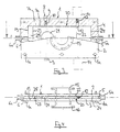
- the quick-closing valve according to Figures 1 to 4 consists of a housing 1, which is composed of a front cover plate 2 with connection piece 15 partially shown in Figures 1 and 3, a mirror-image rear cover plate 3 with connection piece 16 and a frame 4, which with Are screwed together using screws 1a.
- the frame 4 has on its opposite end faces a bore 5 and 6, which are connected via pressure medium connections 5a and 6a to pressure medium systems, not shown.
- connection 5a this is expediently a charged pressure vessel with a valve.
- a rectangular valve plate 20 is slidably arranged in such a way that its opening 21 is aligned with the two connecting pieces 15 and 16 in the open position, whereas the valve plate in the closed position (FIGS. 3 and 4) blocks the connection between the pieces .
- the width and thickness of the valve plate corresponds to the clear cross section of the housing 1, so that it is guided in it like a piston.
- the open position of the valve plate is defined by the position of two locking elements 8, which are each composed of a locking screw 9, a spring 10 and a ball 11, and which protrude elastically into the displacement path.
- valve plate 20 on its end face 22 which is at a sufficient distance from the opposite inside of the housing 24 for uniform pressure distribution, is acted upon by the pressure medium entering the housing through the bore 5, then the locking element 8 (see FIGS. 1 and 3) of the Valve plate pushed away.
- the passage opening 21 of the valve plate 20 is moved to the left so that the piece of the valve plate which lies between the opening 21 and the end face 22 blocks the line.
- a back pressure cushion builds up between the inside of the housing and the other end face 23 of the valve plate 20 because the air can only escape gradually from specially arranged air outlet openings 7a and 7b.
- the valve plate is braked before its end face 23 abuts the inside of the housing 19.
- a further locking element 12 which is pressed into the interior of the housing by a spring 13 behind the valve plate, ensures that the valve plate is held firmly, so that springing back and vibration of the valve plate 22 is excluded.
- the locking element 12 is released by a retraction unit 14 (not shown in more detail), the end face 23 of the valve plate 20 is acted upon by a pressure medium which passes through the bore 6 into the interior of the housing, and thereby the valve plate 20 moved to the right until the locking element 8 comes into engagement again and the passage opening 21 is aligned with the connecting pieces 15 and 16.
Landscapes
- Engineering & Computer Science (AREA)
- General Engineering & Computer Science (AREA)
- Mechanical Engineering (AREA)
- Fluid-Driven Valves (AREA)
- Sliding Valves (AREA)
- Valve Housings (AREA)
- Preventing Unauthorised Actuation Of Valves (AREA)
Claims (8)
- Soupape à fermeture rapide, en particulier pour des conduites à risque d'explosion, comprenant une plaque de soupape (20) qui peut coulisser transversalement par rapport à la conduite, qui ferme la section transversale de la conduite, qui est guidée dans un carter (1) et qui est actionnée par voie pneumatique, le carter (1) fonctionnant comme un cylindre dans lequel la plaque de soupape (20) est soumise directement à l'action du fluide sous pression sur son côté frontal (22), caractérisée par le fait que plusieurs orifices de sortie de l'air (7a, 7b) sont disposés dans le carter le long du trajet de coulissement de la plaque de soupape (20) d'une manière telle qu'un coussin de fluide s'opposant à la pression se forme vers la fin du déplacement de fermeture sur le côté frontal (23) de la plaque de soupape (20) qui est opposé au côté frontal (22) soumis à l'action du fluide sous pression.
- Soupape à fermeture rapide selon la revendication 1, caractérisée par le fait que le carter (1) entoure également la plaque de soupape (20) sur son côté (23) qui est opposé au côté frontal soumis à l'action du fluide sous pression, et qu'il présente à cet endroit des orifices de sortie de l'air (7a, 7b).
- Soupape à fermeture rapide selon la revendication 1 ou 2, caractérisée par le fait que les orifices de sortie de l'air (7a, 7b) sont disposés sur les parois (4) du carter qui s'étendent perpendiculairement audit côté frontal (22) de la plaque de soupape.
- Soupape à fermeture rapide selon la revendication 1, caractérisée par le fait qu'une distance de sécurité destinée à la formation d'un volume mort (25) est prévue entre la plaque de soupape (20) dans sa position de fermeture et le côté intérieur (19) du carter qui est situé dans la direction de la fermeture.
- Soupape à fermeture rapide selon la revendication 1, caractérisée par le fait que les orifices de sortie de l'air (7a, 7b) situés le long du trajet de coulissement présentent une distance suffisante par rapport au côté intérieur (19) du carter qui est situé dans la direction de la fermeture.
- Soupape à fermeture rapide selon la revendication 1, caractérisée par le fait que la plaque de soupape (20) est maintenue dans la région de la position de fermeture par un élément d'arrêt (12).
- Soupape à fermeture rapide selon la revendication 1, caractérisée par le fait que la plaque de soupape (20) est maintenue dans la position d'ouverture par un autre élément d'arrêt (8) qui peut de préférence s'effacer d'une manière élastique.
- Soupape à fermeture rapide selon la revendication 1, caractérisée par le fait que la plaque de soupape (20) est réalisée sous la forme d'une plaque perforée.
Applications Claiming Priority (2)
| Application Number | Priority Date | Filing Date | Title |
|---|---|---|---|
| DE4235068 | 1992-10-17 | ||
| DE4235068A DE4235068A1 (de) | 1992-10-17 | 1992-10-17 | Schnell schließendes Ventil |
Publications (2)
| Publication Number | Publication Date |
|---|---|
| EP0593867A1 EP0593867A1 (fr) | 1994-04-27 |
| EP0593867B1 true EP0593867B1 (fr) | 1997-05-07 |
Family
ID=6470717
Family Applications (1)
| Application Number | Title | Priority Date | Filing Date |
|---|---|---|---|
| EP93112849A Expired - Lifetime EP0593867B1 (fr) | 1992-10-17 | 1993-08-11 | Soupape à fermeture rapide |
Country Status (6)
| Country | Link |
|---|---|
| EP (1) | EP0593867B1 (fr) |
| JP (1) | JPH06129565A (fr) |
| AT (1) | ATE152814T1 (fr) |
| CA (1) | CA2106551A1 (fr) |
| DE (2) | DE4235068A1 (fr) |
| ES (1) | ES2101909T3 (fr) |
Families Citing this family (6)
| Publication number | Priority date | Publication date | Assignee | Title |
|---|---|---|---|---|
| GB2325971B (en) * | 1997-05-29 | 2001-04-04 | Sistag Absperrtechnik | A driving device for a shut-off device in a pipe-line |
| EP0886092B1 (fr) * | 1997-06-16 | 2004-01-02 | Sicpa Holding S.A. | Robinet de dosage et méthode pour la distribution dosée de matériau pâteux |
| JP5177937B2 (ja) * | 2003-09-09 | 2013-04-10 | 財団法人神奈川科学技術アカデミー | スライド式バルブ装置 |
| JP5789388B2 (ja) * | 2011-03-22 | 2015-10-07 | 株式会社松井製作所 | スライド式弁装置、及びこれを備えた輸送切替装置 |
| JP6637224B1 (ja) * | 2018-06-12 | 2020-01-29 | 株式会社アルバック | 仕切弁装置 |
| CN110762239B (zh) * | 2019-11-21 | 2021-07-20 | 西安航天动力研究所 | 一种高压卸荷式火药燃气作动阀 |
Family Cites Families (6)
| Publication number | Priority date | Publication date | Assignee | Title |
|---|---|---|---|---|
| US2877780A (en) * | 1956-10-19 | 1959-03-17 | Beckman & Whitley Inc | Quick release valve |
| US3202162A (en) * | 1963-01-07 | 1965-08-24 | Hans F Eckardt | Normally-closed explosive-actuated valve |
| US3702620A (en) * | 1971-08-10 | 1972-11-14 | Atomic Energy Commission | Actuator system |
| DE2152748A1 (de) * | 1971-10-22 | 1973-04-26 | Marotta Scientific Controls | Schieberventil mit vollem geraden durchfluss |
| DE2851310A1 (de) * | 1977-12-28 | 1979-07-12 | Schaffner Pumpenanlagen Ag | Schieberventil |
| CH649359A5 (de) * | 1980-11-26 | 1985-05-15 | Sulzer Ag | Plattenschieber. |
-
1992
- 1992-10-17 DE DE4235068A patent/DE4235068A1/de not_active Withdrawn
-
1993
- 1993-06-29 JP JP5157754A patent/JPH06129565A/ja active Pending
- 1993-08-11 AT AT93112849T patent/ATE152814T1/de not_active IP Right Cessation
- 1993-08-11 EP EP93112849A patent/EP0593867B1/fr not_active Expired - Lifetime
- 1993-08-11 ES ES93112849T patent/ES2101909T3/es not_active Expired - Lifetime
- 1993-08-11 DE DE59306384T patent/DE59306384D1/de not_active Expired - Fee Related
- 1993-09-20 CA CA002106551A patent/CA2106551A1/fr not_active Abandoned
Also Published As
| Publication number | Publication date |
|---|---|
| CA2106551A1 (fr) | 1994-04-18 |
| DE4235068A1 (de) | 1994-04-21 |
| DE59306384D1 (de) | 1997-06-12 |
| ATE152814T1 (de) | 1997-05-15 |
| JPH06129565A (ja) | 1994-05-10 |
| ES2101909T3 (es) | 1997-07-16 |
| EP0593867A1 (fr) | 1994-04-27 |
Similar Documents
| Publication | Publication Date | Title |
|---|---|---|
| DE3132523C2 (de) | In einem Strömungskreis angeordnetes Absperrventil | |
| DE3117551C2 (fr) | ||
| EP0756663A1 (fr) | Ferme-porte | |
| EP0126291A2 (fr) | Soupape commandée par un fluide sous pression | |
| EP0334924B1 (fr) | Cylindre hydraulique verrouillable | |
| EP0130355B1 (fr) | Amortisseur de culasse pour arme à feu automatique | |
| EP0177620B1 (fr) | Soupape actionnée par un fluide sous pression | |
| EP0593867B1 (fr) | Soupape à fermeture rapide | |
| EP1403576B1 (fr) | Dispositif de fermeture d'une conduite pour la prevention contre l'explosion | |
| DE865245C (de) | Absperrschieber | |
| DE4404467C2 (de) | Hydraulischer Türfeststeller für Kraftwagentüren | |
| EP0842102B1 (fr) | Dispositif de soufflage avec unite soupape externe | |
| DE3018920A1 (de) | Verriegelung fuer druckzylinderkolben | |
| EP0066734B1 (fr) | Dispositif de chasse à air comprimé pour tubes d'éjection et de décharge de bateau sous-marin | |
| DE4129799A1 (de) | Einzelstempelventil mit mechanischer raubvorrichtung und erhoehter abstroemleistung | |
| DE3336778A1 (de) | Greifvorrichtung | |
| DE2249601C3 (de) | Parallel-Platten-Absperrschieber | |
| EP0645567B1 (fr) | Robinet à fermeture automatique | |
| DD268742A5 (de) | Oelmengenkontrollgeraet | |
| DE3342945A1 (de) | Absperrvorrichtung fuer einen stroemungskanal | |
| DE3500907C2 (fr) | ||
| DE1750438A1 (de) | Ventil | |
| DE3026550C2 (de) | Vorrichtung zum Öffnen und Schließen einer Tür, insbesondere einer Feuertür | |
| DE3345631C2 (fr) | ||
| DE4128363C2 (de) | Federspeicherbremszylinder, insbesondere für Bremsanlagen von Nutzfahrzeugen |
Legal Events
| Date | Code | Title | Description |
|---|---|---|---|
| PUAI | Public reference made under article 153(3) epc to a published international application that has entered the european phase |
Free format text: ORIGINAL CODE: 0009012 |
|
| AK | Designated contracting states |
Kind code of ref document: A1 Designated state(s): AT BE CH DE ES FR GB IT LI NL |
|
| 17P | Request for examination filed |
Effective date: 19940421 |
|
| 17Q | First examination report despatched |
Effective date: 19951006 |
|
| GRAG | Despatch of communication of intention to grant |
Free format text: ORIGINAL CODE: EPIDOS AGRA |
|
| GRAH | Despatch of communication of intention to grant a patent |
Free format text: ORIGINAL CODE: EPIDOS IGRA |
|
| GRAH | Despatch of communication of intention to grant a patent |
Free format text: ORIGINAL CODE: EPIDOS IGRA |
|
| GRAA | (expected) grant |
Free format text: ORIGINAL CODE: 0009210 |
|
| AK | Designated contracting states |
Kind code of ref document: B1 Designated state(s): AT BE CH DE ES FR GB IT LI NL |
|
| REF | Corresponds to: |
Ref document number: 152814 Country of ref document: AT Date of ref document: 19970515 Kind code of ref document: T |
|
| REG | Reference to a national code |
Ref country code: CH Ref legal event code: NV Representative=s name: COM PAT AG Ref country code: CH Ref legal event code: EP |
|
| GBT | Gb: translation of ep patent filed (gb section 77(6)(a)/1977) |
Effective date: 19970509 |
|
| REF | Corresponds to: |
Ref document number: 59306384 Country of ref document: DE Date of ref document: 19970612 |
|
| PGFP | Annual fee paid to national office [announced via postgrant information from national office to epo] |
Ref country code: BE Payment date: 19970624 Year of fee payment: 5 |
|
| ET | Fr: translation filed | ||
| REG | Reference to a national code |
Ref country code: ES Ref legal event code: FG2A Ref document number: 2101909 Country of ref document: ES Kind code of ref document: T3 |
|
| PGFP | Annual fee paid to national office [announced via postgrant information from national office to epo] |
Ref country code: ES Payment date: 19970805 Year of fee payment: 5 |
|
| PGFP | Annual fee paid to national office [announced via postgrant information from national office to epo] |
Ref country code: AT Payment date: 19970829 Year of fee payment: 5 |
|
| PLBE | No opposition filed within time limit |
Free format text: ORIGINAL CODE: 0009261 |
|
| 26N | No opposition filed | ||
| PG25 | Lapsed in a contracting state [announced via postgrant information from national office to epo] |
Ref country code: AT Free format text: LAPSE BECAUSE OF NON-PAYMENT OF DUE FEES Effective date: 19980811 |
|
| PG25 | Lapsed in a contracting state [announced via postgrant information from national office to epo] |
Ref country code: ES Free format text: LAPSE BECAUSE OF THE APPLICANT RENOUNCES Effective date: 19980812 |
|
| PG25 | Lapsed in a contracting state [announced via postgrant information from national office to epo] |
Ref country code: BE Free format text: LAPSE BECAUSE OF NON-PAYMENT OF DUE FEES Effective date: 19980831 |
|
| BERE | Be: lapsed |
Owner name: PRODUKTIONS A.G. GISWIL PAGG Effective date: 19980831 |
|
| REG | Reference to a national code |
Ref country code: ES Ref legal event code: FD2A Effective date: 20001102 |
|
| PGFP | Annual fee paid to national office [announced via postgrant information from national office to epo] |
Ref country code: FR Payment date: 20010504 Year of fee payment: 9 |
|
| PGFP | Annual fee paid to national office [announced via postgrant information from national office to epo] |
Ref country code: GB Payment date: 20010705 Year of fee payment: 9 |
|
| PGFP | Annual fee paid to national office [announced via postgrant information from national office to epo] |
Ref country code: DE Payment date: 20010827 Year of fee payment: 9 Ref country code: CH Payment date: 20010827 Year of fee payment: 9 |
|
| PGFP | Annual fee paid to national office [announced via postgrant information from national office to epo] |
Ref country code: NL Payment date: 20010831 Year of fee payment: 9 |
|
| REG | Reference to a national code |
Ref country code: GB Ref legal event code: IF02 |
|
| PG25 | Lapsed in a contracting state [announced via postgrant information from national office to epo] |
Ref country code: GB Free format text: LAPSE BECAUSE OF NON-PAYMENT OF DUE FEES Effective date: 20020811 |
|
| PG25 | Lapsed in a contracting state [announced via postgrant information from national office to epo] |
Ref country code: LI Free format text: LAPSE BECAUSE OF NON-PAYMENT OF DUE FEES Effective date: 20020831 Ref country code: CH Free format text: LAPSE BECAUSE OF NON-PAYMENT OF DUE FEES Effective date: 20020831 |
|
| PG25 | Lapsed in a contracting state [announced via postgrant information from national office to epo] |
Ref country code: NL Free format text: LAPSE BECAUSE OF NON-PAYMENT OF DUE FEES Effective date: 20030301 Ref country code: DE Free format text: LAPSE BECAUSE OF NON-PAYMENT OF DUE FEES Effective date: 20030301 |
|
| GBPC | Gb: european patent ceased through non-payment of renewal fee |
Effective date: 20020811 |
|
| REG | Reference to a national code |
Ref country code: CH Ref legal event code: PL |
|
| PG25 | Lapsed in a contracting state [announced via postgrant information from national office to epo] |
Ref country code: FR Free format text: LAPSE BECAUSE OF NON-PAYMENT OF DUE FEES Effective date: 20030430 |
|
| NLV4 | Nl: lapsed or anulled due to non-payment of the annual fee |
Effective date: 20030301 |
|
| REG | Reference to a national code |
Ref country code: FR Ref legal event code: ST |
|
| PG25 | Lapsed in a contracting state [announced via postgrant information from national office to epo] |
Ref country code: IT Free format text: LAPSE BECAUSE OF NON-PAYMENT OF DUE FEES;WARNING: LAPSES OF ITALIAN PATENTS WITH EFFECTIVE DATE BEFORE 2007 MAY HAVE OCCURRED AT ANY TIME BEFORE 2007. THE CORRECT EFFECTIVE DATE MAY BE DIFFERENT FROM THE ONE RECORDED. Effective date: 20050811 |