EP0593899A1 - Dispositif pour mettre en rotation un fil de sciage - Google Patents
Dispositif pour mettre en rotation un fil de sciage Download PDFInfo
- Publication number
- EP0593899A1 EP0593899A1 EP93114729A EP93114729A EP0593899A1 EP 0593899 A1 EP0593899 A1 EP 0593899A1 EP 93114729 A EP93114729 A EP 93114729A EP 93114729 A EP93114729 A EP 93114729A EP 0593899 A1 EP0593899 A1 EP 0593899A1
- Authority
- EP
- European Patent Office
- Prior art keywords
- rope
- wire
- saw
- roller
- rotating roller
- Prior art date
- Legal status (The legal status is an assumption and is not a legal conclusion. Google has not performed a legal analysis and makes no representation as to the accuracy of the status listed.)
- Granted
Links
Images

Classifications
-
- B—PERFORMING OPERATIONS; TRANSPORTING
- B23—MACHINE TOOLS; METAL-WORKING NOT OTHERWISE PROVIDED FOR
- B23D—PLANING; SLOTTING; SHEARING; BROACHING; SAWING; FILING; SCRAPING; LIKE OPERATIONS FOR WORKING METAL BY REMOVING MATERIAL, NOT OTHERWISE PROVIDED FOR
- B23D57/00—Sawing machines or sawing devices not covered by one of the preceding groups B23D45/00 - B23D55/00
- B23D57/003—Sawing machines or sawing devices working with saw wires, characterised only by constructional features of particular parts
- B23D57/0053—Sawing machines or sawing devices working with saw wires, characterised only by constructional features of particular parts of drives for saw wires; of wheel mountings; of wheels
Definitions
- the invention relates to a device on wire saws for generating a constant and uniform rotational movement of the saw rope during the cut.
- the saw cable consists of a rope braided from several metal wires with attached cutting beads, which contain high-performance cutting material such as diamond and / or cubic boron nitride in a preferably metallic bond.
- high-performance cutting material such as diamond and / or cubic boron nitride in a preferably metallic bond.
- the saw rope twisting device was developed, which causes the rope to inevitably turn the rope during the sawing process, which ensures circular and concentric bead wear.
- the object of the invention is the rope rotating device described. It generates the described inevitable rotational movement of the saw cable safely and reliably in all wire saw applications.
- At least one steplessly profiled rope rotating roller with at least one rope entry area and a rope exit area which is comparatively smaller in diameter is provided.
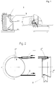
- the basic principle of the rope rotating device is based on a preferably conically shaped roller (1) with a rubber or plastic covering. If a saw cable (2) is now fed onto the larger diameter of the conical roller profile, it will try on the roller (1) in the further course, due to the tensile force in the saw cable, to the smaller diameter of the roller by the amount (s) in Fig 4 to migrate. Since the friction between the diamond pearls and the support on the reel is very large, the rope is caused to move in the form of rolling movements and not by slipping. The rotary movement is thus generated and must be passed on to the remaining part of the rope via the elastic torsional resistance of the rope. This rotary movement is effectively passed on if the rope was pre-twisted with approx. 2 revolutions per linear meter of rope before use.
- the drive wheel (1 ') according to FIG. 2 can also be designed as a rope rotating roller, which is particularly advantageous for short rope lengths.
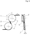
- the wrap angle ⁇ according to FIG. 3 can start from very small angles of approximately 30 ° to the special case of 360 ° corresponding to a full wrap be.
- constructive measures must be taken to ensure that the rope parts entering and leaving the rope rotating roller do not touch each other.
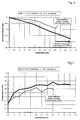
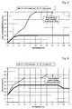
- High wear is to be expected when touching the two rope parts because the relative speed at the point of contact is about 3 (m / s) due to the frequently used cutting speed of 21 (m / s), as determined in the calculation example in Table 1 for the practical application data has been.
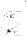
- the cone angle ⁇ in FIG. 4 only influences the force component F r with which the rope is forced to roll, but not the frequency of rotation of the rope about its axis.
- roller profiles modified according to the invention are conceivable, as exemplified in FIG. 5.
- the basic principle according to the invention of the unwinding of the rope in the course of the path covered in the wrap angle ⁇ remains largely unaffected by the embodiment of the rope running profile.
- a basic distinction must be made between one-way and two-way profiles.
- the rope running profile is preferably carried out symmetrically.
- the distance q between the rope inlet and the rope outlet on the rope rotating roller essentially determines the frequency of rotation of the rope in accordance with the calculation of the turning effect in the following calculation example. As the tests showed, a set distance q of 2-4 mm is sufficient for a reliable rope turning effect. Significantly higher q values generated harmful vibrations in the rope, so they should be avoided.
- the rope with the ⁇ d is displaced by a distance q when it rotates around the rope rotating roller (1) (1 ') and must therefore roll the distance s down the cone.
- s q / cos ⁇
- the length of the saw rope (2) located on the cone (4) is determined by the diameter D of the rope rotating roller (1) and the wrap angle ⁇ .
- the rope can be run in by connecting a guide roller (3) at any distance (e), preferably approx. 1 to 2 times the diameter of the rope rotating roller (1).
- the axis of this guide roller (3) can be at an entry angle ( ⁇ ) to the rope rotating roller (1) to enable a gentle rope run. It is advantageous to use a commercially available self-adjusting swivel castor.
- FIGS. 1 and 3 represents a possible embodiment of the invention of the rope turning device.
- additions with additional guide rollers in the rope inlet and rope outlet are conceivable, for example, for damping rope vibrations with long rope lengths, without the same effect according to the invention of the actual rope turning device influence.
- an inverted arrangement of the rope rotating roller (1) and the guide roller (3) with respect to the direction of the rope cutting has no restrictive effect on the aim of the invention, since in the opposite direction of the rope cutting only the direction of rotation the rope around its axis is also reversed, and otherwise no effect on the constant rotation according to the invention was found.
Landscapes
- Engineering & Computer Science (AREA)
- Mechanical Engineering (AREA)
- Processing Of Stones Or Stones Resemblance Materials (AREA)
- Ropes Or Cables (AREA)
- Lift-Guide Devices, And Elevator Ropes And Cables (AREA)
Priority Applications (1)
| Application Number | Priority Date | Filing Date | Title |
|---|---|---|---|
| PCT/EP1993/002896 WO1994008746A1 (fr) | 1992-10-21 | 1993-10-21 | Mecanisme rotatif de cable de scie |
Applications Claiming Priority (2)
| Application Number | Priority Date | Filing Date | Title |
|---|---|---|---|
| AT0208092A AT398935B (de) | 1992-10-21 | 1992-10-21 | Sägeseildrehvorrichtung |
| AT2080/92 | 1992-10-21 |
Publications (2)
| Publication Number | Publication Date |
|---|---|
| EP0593899A1 true EP0593899A1 (fr) | 1994-04-27 |
| EP0593899B1 EP0593899B1 (fr) | 1997-04-16 |
Family
ID=3527332
Family Applications (1)
| Application Number | Title | Priority Date | Filing Date |
|---|---|---|---|
| EP93114729A Expired - Lifetime EP0593899B1 (fr) | 1992-10-21 | 1993-09-14 | Dispositif pour mettre en rotation un fil de sciage |
Country Status (3)
| Country | Link |
|---|---|
| EP (1) | EP0593899B1 (fr) |
| AT (2) | AT398935B (fr) |
| DE (2) | DE59306169D1 (fr) |
Cited By (3)
| Publication number | Priority date | Publication date | Assignee | Title |
|---|---|---|---|---|
| EP0694366A1 (fr) * | 1994-07-29 | 1996-01-31 | Shin-Etsu Handotai Company Limited | Appareil de sciage par fil |
| EP2216117A1 (fr) * | 2009-02-10 | 2010-08-11 | Betag-Betontaglio SA | Scie à câble ainsi que procédé de fonctionnement d'une telle unité de scie à câble |
| CN114033366A (zh) * | 2021-10-15 | 2022-02-11 | 长沙百川超硬材料工具有限公司 | 一种绳锯机锯绳自转的方法 |
Families Citing this family (1)
| Publication number | Priority date | Publication date | Assignee | Title |
|---|---|---|---|---|
| DE19936834A1 (de) * | 1999-08-05 | 2001-02-15 | Wacker Siltronic Halbleitermat | Sägedraht und Verfahren zum Trennläppen von sprödharten Werkstücken |
Citations (3)
| Publication number | Priority date | Publication date | Assignee | Title |
|---|---|---|---|---|
| FR778280A (fr) * | 1934-09-13 | 1935-03-13 | Installation pour le travail mécanique du marbre | |
| US3682030A (en) * | 1970-11-04 | 1972-08-08 | Gerald R Harris | Pivotal arm band saw |
| FR2655904A1 (fr) * | 1989-12-14 | 1991-06-21 | Diamind Sa | Systeme de decoupe de corps solides du type "a cable". |
Family Cites Families (7)
| Publication number | Priority date | Publication date | Assignee | Title |
|---|---|---|---|---|
| DE189787C (fr) * | ||||
| US1050896A (en) * | 1912-06-25 | 1913-01-21 | Harry Wilson | Sheave-block. |
| FR1199566A (fr) * | 1958-03-06 | 1959-12-15 | Touret pour fil de sciage, et machines à scier utilisant ce touret | |
| GB1491614A (en) * | 1974-06-11 | 1977-11-09 | Graham R | Winches |
| SU684241A1 (ru) * | 1978-02-10 | 1979-09-05 | Украинский научно-исследовательский и проектно-конструкторский институт подземной гидравлической добычи угля "УкрНИИгидроуголь" | Многообхватный канатоведущий шкив |
| SU688753A1 (ru) * | 1978-03-14 | 1979-09-30 | Украинский Научно-Исследовательский И Проектно-Конструкторский Институт Подземной Гидравлической Добычи Угля | Многообхватный канатоведущий шкив |
| FR2645518B1 (fr) * | 1989-04-05 | 1991-08-16 | Brenot Claude | Cabestan a auto-maintien a dents articulees |
-
1992
- 1992-10-21 AT AT0208092A patent/AT398935B/de not_active IP Right Cessation
-
1993
- 1993-09-14 DE DE59306169T patent/DE59306169D1/de not_active Expired - Fee Related
- 1993-09-14 DE DE9313907U patent/DE9313907U1/de not_active Expired - Lifetime
- 1993-09-14 EP EP93114729A patent/EP0593899B1/fr not_active Expired - Lifetime
- 1993-09-14 AT AT93114729T patent/ATE151675T1/de active
Patent Citations (3)
| Publication number | Priority date | Publication date | Assignee | Title |
|---|---|---|---|---|
| FR778280A (fr) * | 1934-09-13 | 1935-03-13 | Installation pour le travail mécanique du marbre | |
| US3682030A (en) * | 1970-11-04 | 1972-08-08 | Gerald R Harris | Pivotal arm band saw |
| FR2655904A1 (fr) * | 1989-12-14 | 1991-06-21 | Diamind Sa | Systeme de decoupe de corps solides du type "a cable". |
Cited By (4)
| Publication number | Priority date | Publication date | Assignee | Title |
|---|---|---|---|---|
| EP0694366A1 (fr) * | 1994-07-29 | 1996-01-31 | Shin-Etsu Handotai Company Limited | Appareil de sciage par fil |
| US5907988A (en) * | 1994-07-29 | 1999-06-01 | Shin-Etsu Handotai Co., Ltd. | Wire saw apparatus |
| EP2216117A1 (fr) * | 2009-02-10 | 2010-08-11 | Betag-Betontaglio SA | Scie à câble ainsi que procédé de fonctionnement d'une telle unité de scie à câble |
| CN114033366A (zh) * | 2021-10-15 | 2022-02-11 | 长沙百川超硬材料工具有限公司 | 一种绳锯机锯绳自转的方法 |
Also Published As
| Publication number | Publication date |
|---|---|
| ATE151675T1 (de) | 1997-05-15 |
| EP0593899B1 (fr) | 1997-04-16 |
| ATA208092A (de) | 1994-07-15 |
| DE59306169D1 (de) | 1997-05-22 |
| DE9313907U1 (de) | 1993-11-25 |
| AT398935B (de) | 1995-02-27 |
Similar Documents
| Publication | Publication Date | Title |
|---|---|---|
| EP0496049A1 (fr) | Perfectionnement au dispositif pour l'alimentation d'un câble dans un automate pour façonner des câbles | |
| DE2353895B2 (de) | Vorrichtung zum zerschneiden von glasstraengen | |
| DE3308586C2 (de) | Vorrichtung zur spitzenlosen, spanenden Außenfeinbearbeitung von länglichen Werkstücken | |
| DE60111798T2 (de) | Hochgeschwindigkeits-Schneidevorrichtung zum Schneiden von Verstärkungselementen für Luftreifen. | |
| DE3128110A1 (de) | "verfahren und einrichtung zum schneiden von flankenoffenen keilriemen" | |
| EP0593899B1 (fr) | Dispositif pour mettre en rotation un fil de sciage | |
| DE2321477A1 (de) | Verfahren und vorrichtung zum abrichten und schaerfen von schleifscheiben | |
| WO1997017179A1 (fr) | Dispositif pour lisser des plaques et baguettes | |
| DE2931958A1 (de) | Seilzug | |
| EP0439830A2 (fr) | Dispositif de traitement d'une feuille continue | |
| EP0088347B1 (fr) | Dispositif à chaînes de tirage et de freinage pour la stabilisation des tensions de bandes métalliques | |
| EP1749589A1 (fr) | Méthode et appareil pour nettoyer un fil ou la surface externe d'un tube | |
| DE4239212A1 (de) | Seilsägespannvorrichtung | |
| DE19808804A1 (de) | Maschine zur Oberflächenbearbeitung mindestens einer textilen Warenbahn, insbesondere zum Rauhen und/oder Schmirgeln od. dgl. | |
| DE69808879T2 (de) | Vorrichtung zur Reinigung von Draht für die Herstellung von gezogenen Metalldrähten | |
| WO1994008746A1 (fr) | Mecanisme rotatif de cable de scie | |
| DE2504696C3 (de) | Kettenspannvorrichtung für kettenbetriebene Arbeitsmaschinen, insbesondere im Bergbau | |
| DE102010021959A1 (de) | Sägeseil | |
| DE2740212C2 (de) | Sägebandrolle | |
| DE69608005T2 (de) | Fördervorrichtung für Schüttgüter | |
| DE4217808A1 (de) | Verfahren und vorrichtung zum beseitigen eines teiles eines stranges eines kraftuebertragungsriemens | |
| DE10332711A1 (de) | Riemen für Wickelvorrichtung | |
| EP1297924A1 (fr) | Scie à fil | |
| DE3916289A1 (de) | Geruest zum ziehen oder bremsen von baendern | |
| DE102006058819A1 (de) | Verfahren zum Abtrennen einer Vielzahl von Scheiben von einem Werkstück |
Legal Events
| Date | Code | Title | Description |
|---|---|---|---|
| PUAI | Public reference made under article 153(3) epc to a published international application that has entered the european phase |
Free format text: ORIGINAL CODE: 0009012 |
|
| AK | Designated contracting states |
Kind code of ref document: A1 Designated state(s): AT BE CH DE DK ES FR GB IT LI NL PT SE |
|
| 17P | Request for examination filed |
Effective date: 19940301 |
|
| GBC | Gb: translation of claims filed (gb section 78(7)/1977) | ||
| GRAG | Despatch of communication of intention to grant |
Free format text: ORIGINAL CODE: EPIDOS AGRA |
|
| GRAH | Despatch of communication of intention to grant a patent |
Free format text: ORIGINAL CODE: EPIDOS IGRA |
|
| GRAH | Despatch of communication of intention to grant a patent |
Free format text: ORIGINAL CODE: EPIDOS IGRA |
|
| 17Q | First examination report despatched |
Effective date: 19961004 |
|
| GRAA | (expected) grant |
Free format text: ORIGINAL CODE: 0009210 |
|
| AK | Designated contracting states |
Kind code of ref document: B1 Designated state(s): AT BE CH DE DK ES FR GB IT LI NL PT SE |
|
| PG25 | Lapsed in a contracting state [announced via postgrant information from national office to epo] |
Ref country code: NL Effective date: 19970416 Ref country code: IT Free format text: LAPSE BECAUSE OF FAILURE TO SUBMIT A TRANSLATION OF THE DESCRIPTION OR TO PAY THE FEE WITHIN THE PRE;WARNING: LAPSES OF ITALIAN PATENTS WITH EFFECTIVE DATE BEFORE 2007 MAY HAVE OCCURRED AT ANY TIME BEFORE 2007. THE CORRECT EFFECTIVE DATE MAY BE DIFFERENT FROM THE ONE RECORDED.SCRIBED TIME-LIMIT Effective date: 19970416 Ref country code: FR Effective date: 19970416 Ref country code: ES Free format text: THE PATENT HAS BEEN ANNULLED BY A DECISION OF A NATIONAL AUTHORITY Effective date: 19970416 Ref country code: DK Effective date: 19970416 |
|
| REF | Corresponds to: |
Ref document number: 151675 Country of ref document: AT Date of ref document: 19970515 Kind code of ref document: T |
|
| REG | Reference to a national code |
Ref country code: CH Ref legal event code: EP |
|
| REF | Corresponds to: |
Ref document number: 59306169 Country of ref document: DE Date of ref document: 19970522 |
|
| GBT | Gb: translation of ep patent filed (gb section 77(6)(a)/1977) |
Effective date: 19970606 |
|
| PG25 | Lapsed in a contracting state [announced via postgrant information from national office to epo] |
Ref country code: SE Effective date: 19970716 Ref country code: PT Effective date: 19970716 |
|
| NLV1 | Nl: lapsed or annulled due to failure to fulfill the requirements of art. 29p and 29m of the patents act | ||
| PGFP | Annual fee paid to national office [announced via postgrant information from national office to epo] |
Ref country code: AT Payment date: 19970903 Year of fee payment: 5 |
|
| EN | Fr: translation not filed | ||
| PG25 | Lapsed in a contracting state [announced via postgrant information from national office to epo] |
Ref country code: BE Free format text: LAPSE BECAUSE OF NON-PAYMENT OF DUE FEES Effective date: 19970930 |
|
| PGFP | Annual fee paid to national office [announced via postgrant information from national office to epo] |
Ref country code: CH Payment date: 19971029 Year of fee payment: 5 |
|
| PGFP | Annual fee paid to national office [announced via postgrant information from national office to epo] |
Ref country code: GB Payment date: 19971112 Year of fee payment: 5 |
|
| PLBE | No opposition filed within time limit |
Free format text: ORIGINAL CODE: 0009261 |
|
| BERE | Be: lapsed |
Owner name: TYROLIT SCHLEIFMITTELWERKE SWAROVSKI K.G. Effective date: 19970930 |
|
| 26N | No opposition filed | ||
| PG25 | Lapsed in a contracting state [announced via postgrant information from national office to epo] |
Ref country code: DE Free format text: LAPSE BECAUSE OF NON-PAYMENT OF DUE FEES Effective date: 19980603 |
|
| PG25 | Lapsed in a contracting state [announced via postgrant information from national office to epo] |
Ref country code: GB Free format text: LAPSE BECAUSE OF NON-PAYMENT OF DUE FEES Effective date: 19980914 Ref country code: AT Free format text: LAPSE BECAUSE OF NON-PAYMENT OF DUE FEES Effective date: 19980914 |
|
| PG25 | Lapsed in a contracting state [announced via postgrant information from national office to epo] |
Ref country code: LI Free format text: LAPSE BECAUSE OF NON-PAYMENT OF DUE FEES Effective date: 19980930 Ref country code: CH Free format text: LAPSE BECAUSE OF NON-PAYMENT OF DUE FEES Effective date: 19980930 |
|
| GBPC | Gb: european patent ceased through non-payment of renewal fee |
Effective date: 19980914 |
|
| REG | Reference to a national code |
Ref country code: CH Ref legal event code: PL |