EP0593903A1 - Réflecteurs à forme de surface identique en arrangement semi-tandem - Google Patents
Réflecteurs à forme de surface identique en arrangement semi-tandem Download PDFInfo
- Publication number
- EP0593903A1 EP0593903A1 EP93114849A EP93114849A EP0593903A1 EP 0593903 A1 EP0593903 A1 EP 0593903A1 EP 93114849 A EP93114849 A EP 93114849A EP 93114849 A EP93114849 A EP 93114849A EP 0593903 A1 EP0593903 A1 EP 0593903A1
- Authority
- EP
- European Patent Office
- Prior art keywords
- shaped
- reflector
- arrangement
- reflective
- shaped reflective
- Prior art date
- Legal status (The legal status is an assumption and is not a legal conclusion. Google has not performed a legal analysis and makes no representation as to the accuracy of the status listed.)
- Granted
Links
Images

Classifications
-
- H—ELECTRICITY
- H01—ELECTRIC ELEMENTS
- H01Q—ANTENNAS, i.e. RADIO AERIALS
- H01Q15/00—Devices for reflection, refraction, diffraction or polarisation of waves radiated from an antenna, e.g. quasi-optical devices
- H01Q15/14—Reflecting surfaces; Equivalent structures
- H01Q15/22—Reflecting surfaces; Equivalent structures functioning also as polarisation filter
-
- H—ELECTRICITY
- H01—ELECTRIC ELEMENTS
- H01Q—ANTENNAS, i.e. RADIO AERIALS
- H01Q25/00—Antennas or antenna systems providing at least two radiating patterns
- H01Q25/007—Antennas or antenna systems providing at least two radiating patterns using two or more primary active elements in the focal region of a focusing device
Definitions
- This invention relates generally to antenna reflector systems and, more particularly, to arranging two dual-gridded shaped reflectors for transmitting and/or receiving orthogonally polarized energy waves.
- a shaped reflector advantageously allows the use of a single feed horn to obtain the desired beam pattern.
- Energy waves such as those employed in the radio frequency spectrum frequently have two orthogonal components which are orthogonally polarized with respect to each other.
- the first orthogonal component is conventionally known as the horizontal component, while the second is generally known as the vertical component.
- the orthogonal polarization of energy waves allows for the possibility of broadcasting two different signals at the same operating frequency. In doing so, one signal is derived from the horizontally polarized component and the second signal is derived from the vertically polarized component.
- Known antenna systems have generally employed orthogonally polarized components to double the information sent at the same frequency by using two separate antennas. More recently, conventional antenna systems have employed two reflectors arranged in a shared aperture tandem arrangement so that one reflector is positioned directly behind the other. Each of the two reflectors typically have an array of reflective grid lines which form reflective surfaces. The grid lines on one reflector reflect signals which have a first polarity. In contrast, the grid lines on the other reflector are arranged orthogonal to those of the first and reflect signals which have a second polarity.
- each reflector has its own focal point in which an associated feed horn is usually positioned to communicate therewith. Since each feed horn may not occupy the same physical location, the conventional approach requires that the reflectors generally be formed with slightly different shapes. This approach prevents the focal points from converging along a common focal axis while providing somewhat equal shaped beam patterns with similar gain contours.
- the conventional orthogonally polarized reflector arrangement generally requires two shaped reflectors which have different shaped reflective surfaces.
- the different shaped reflectors are individually formed with two separate mandrels or other casting devices.
- two separate mandrels are usually required in order to form reflectors which have a particular shaped beam coverage. This requirement generally involves a considerable amount of cost and time to design and produce the separate mandrels.
- a reflector arrangement which has shaped reflectors that may be formed with a single mandrel.
- two dual-gridded reflectors which have identical shaped reflective surfaces for transmitting and/or receiving orthogonally polarized energy.
- a method of forming the reflectors for such a reflector arrangement is further desirable to provide for a method of forming the reflectors for such a reflector arrangement.
- a shaped reflector arrangement for reflecting orthogonally polarized energy.
- the reflector arrangement includes a first shaped reflective surface formed on a first reflector body surface for providing a first shaped beam coverage.
- a second shaped reflective surface is provided on a second reflector body surface for providing a second shaped beam coverage.
- the first and second shaped reflective surfaces have substantially identical surface shapes and are arranged in an offset and tandem arrangement so that the first and second reflective surfaces have separate first and second focal points while providing substantially identical first and second shaped beam coverages.
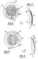
- FIGS. 1 and 2 a pair of shaped reflectors 10 and 20 are shown arranged in a tandem arrangement, one behind the other.
- the shaped reflectors 10 and 20 have identical shaped dual-gridded reflective portions for transmitting orthogonally polarized signals within substantially identical beam patterns. However, the reflective portions are offset from one another to provide for separate focal axes with separate focal points.
- the shaped reflector arrangement according to the present invention allows for the pair of reflectors 10 and 20 to be formed with a single mandrel.
- the first or front shaped reflector 10 includes a first shaped reflective surface 12.
- the reflective surface 12 is made up of a first array of substantially parallel grid line strips 13 which form a horizontal grid pattern.
- the front reflector 10 further includes a first shell-like body member 14.
- the first reflective surface 12 is formed on a portion of the first shell-like body member 14. As a result, the first shell-like body member 14 surrounds the back side of the first shaped reflective surface 12 and further extends over extended portions thereon.
- the second or rear shaped reflector 20 has a second reflective surface 22 which is likewise made up of a second array of substantially parallel grid line strips 23.
- the grid line strips 23 form a vertical grid which is orthogonal to the horizontal grid provided by the first array of grid line strips 13.
- the first reflective surface 12 reflects energy polarized in a first direction while the second reflective surface 22 reflects energy polarized in a second direction which is orthogonal to the first direction.
- the rear reflector 20 likewise includes a second shell-like body member 24.
- the second reflective surface 22 is formed on a portion of the second shell-like body member 24.
- the second reflective surface 22 is formed with a shaped surface contour identical to that of the first reflective surface 12.
- the first and second shell-like body members 14 and 24 generally do not have identical surface contours. Instead, the shell-like body members 14 and 24 position the reflective surfaces 12 and 22 in an offset orientation while providing extensions so that the body members 14 and 24 are substantially equal sized and positioned one behind the other.
- the reflective grid line strips 13 and 23 may be formed on the first and second body members 14 and 24 in a number of ways.
- wires or thin copper strips are etched on a thin polyimide film which in turn is embedded within or adhered to the first and second shell-like body members 14 and 24.
- the grid line strips 13 and 23 may include precision etched copper lines etched in a suitable dielectric carrier which is formed in or adhered to the body members 14 and 24.
- Each of the first and second reflective surfaces 12 and 24 are transparent to incident energy polarized in a direction orthogonal to the reflective grid formed thereon.
- the first reflective surface 12 bearing the horizontal grid is transparent to vertically polarized incident energy.
- the second reflective surface 22 bearing the vertical grid is transparent to incident energy signals polarized horizontally.
- the front and rear shaped reflectors 10 and 20 are arranged so that the front reflector 10 is located directly in front of the rear reflector 20.
- the front and rear reflectors 10 and 20 are connected together and held in a desired position by a plurality of spaced connectors 32.
- the first shell-like body member 14 is located directly in front of the second shell-like body member 24 in a tandem arrangement so that the front and rear shaped reflectors 10 and 20 are compactly arranged within a common shared aperture.
- the first and second body members 14 and 24 generally have different surface shapes, however the reflective portions 12 and 22 formed thereon have identical surface contours with grid patterns arranged orthogonal to each other. That is, the first and second reflective surfaces 12 and 22 have identical shaped surface contours which reflect signals within substantially identical far-field beam patterns 15 and 25.
- the first shaped reflective surface 12 and the second shaped reflective surface 22 are located in an offset and tandem manner. That is, the second reflective surface 22 is positioned behind the first reflective surface 12 and displaced therefrom by offset dimensions X and Y.
- the first reflective surface 12 has a first focal point 16 along a first focal axis 17 which is equally offset and tandem from the focal point 26 along a second focal axis 27 of the second reflective surface 22.
- First and second focal axes 17 and 27 are representative of focal axes which would generally be present with parabolic surfaces that may be used to generate the surface contour of the shaped reflectors.
- First and second feed horns 18 and 28 are located in the vicinity of the first and second focal points 16 and 26 for communicating with the first and second reflective surfaces 12 and 22, respectively. As a consequence, the first and second feed horns 18 and 28 are displaced from one another by offset dimensions X and Y in a manner similar to the arrangement of the reflective surfaces 12 and 22.
- the present invention advantageously provides front and rear shaped reflectors 10 and 20 which may be formed with a single shaped mandrel.
- FIGS. 3 through 6 the formation of the first and second shaped reflectors 10 and 20 with a single mandrel 30 will now be described.
- FIGS. 3 and 4 illustrate the fabrication of the front shaped reflector 10 with the mandrel 30.
- the mandrel 30 generally has a solid surface with a reflective portion thereof which has a surface contour for shaping the shaped reflective surfaces 12 and 22.
- the mandrel 30 further has a surface which extends beyond the reflective surface portion so as to allow the formation of extensions beyond the reflective portion.
- the front reflector 10 may be fabricated with an extension extending to one side of the mandrel 30 while the second reflector 20 has an extension extending to the other side thereof.
- the front reflector 10 is fabricated by initially placing grid line strips 13 on the reflective portion of the mandrel 30.
- a thin plastic material which may include aramid fiber such as KevlarTM cloth disposed on both sides of a honeycomb core is disposed over the surface of the mandrel 30 which is used to form the first shell-like body member 14.
- the thin plastic material has approximately a 1/4" thickness.
- the plastic material covers the grid line strips 13 and further covers extended portions of the mandrel 30.
- the thin plastic material is then cut to form the desired shape of the first shell-like body member 14 and removed from the mandrel 30.
- the rear reflector 20 is likewise formed in a similar manner with the same mandrel 30. In doing so, grid line strips 23 are placed on the same reflective portion of the mandrel 30. However, the grid line strips 23 are arranged orthogonal to the grid line strips 13 which form the first reflective surface 12. A similar thin plastic material is disposed on top of the mandrel 30 so as to cover the line strips 23 and extended portions of the mandrel 30. The plastic material is then cut to form the second shell-like body member 24.
- a second reflective surface 22 is formed which has a surface contour identical to the first reflective surface 22.
- the second shell-like body member 24 is generally molded with a different portion of the mandrel 30 and therefore may have a shape different than the first body member 14.
- the front and rear reflectors 10 and 20 are then arranged one behind the other and held in place by connectors 32.
- This invention enables the formation of the front and rear reflectors 10 and 20 with a single mandrel 30. While the reflective portions 12 and 22 and the shell-like body members 14 and 24 have been shown and described in connection with an example thereof, the invention is not limited to the shapes provided herein.
Landscapes
- Physics & Mathematics (AREA)
- Electromagnetism (AREA)
- Aerials With Secondary Devices (AREA)
Applications Claiming Priority (2)
| Application Number | Priority Date | Filing Date | Title |
|---|---|---|---|
| US94819192A | 1992-09-21 | 1992-09-21 | |
| US948191 | 1992-09-21 |
Publications (2)
| Publication Number | Publication Date |
|---|---|
| EP0593903A1 true EP0593903A1 (fr) | 1994-04-27 |
| EP0593903B1 EP0593903B1 (fr) | 1998-05-13 |
Family
ID=25487448
Family Applications (1)
| Application Number | Title | Priority Date | Filing Date |
|---|---|---|---|
| EP93114849A Expired - Lifetime EP0593903B1 (fr) | 1992-09-21 | 1993-09-15 | Réflecteurs à forme de surface identique en arrangement semi-tandem |
Country Status (5)
| Country | Link |
|---|---|
| US (1) | US5673056A (fr) |
| EP (1) | EP0593903B1 (fr) |
| JP (1) | JP2897970B2 (fr) |
| CA (1) | CA2105745C (fr) |
| DE (1) | DE69318505T2 (fr) |
Cited By (7)
| Publication number | Priority date | Publication date | Assignee | Title |
|---|---|---|---|---|
| GB2323971A (en) * | 1997-04-03 | 1998-10-07 | Daimler Benz Aerospace Ag | Production of polarization selective reflectors |
| DE19945062A1 (de) * | 1999-09-20 | 2001-04-12 | Daimler Chrysler Ag | Reflektor mit geformter Oberfläche und räumlich getrennten Foki zur Ausleuchtung identischer Gebiete, Antennensystem und Verfahren zur Oberflächenermittlung |
| RU2175802C1 (ru) * | 2000-04-25 | 2001-11-10 | Федеральное государственное унитарное предприятие "Всероссийский научно-исследовательский институт "Градиент" | Двухполяризационная зеркальная антенна |
| EP1244176A1 (fr) * | 2001-03-22 | 2002-09-25 | Alcatel | Antenne à reflecteur double avec deflecteur |
| EP1020953A3 (fr) * | 1999-01-15 | 2003-02-05 | TRW Inc. | Antenne à faisceaux multiples à zones sélectives en fréquence ou sensibles à la polarisation |
| EP1207584A3 (fr) * | 2000-11-15 | 2004-01-02 | The Boeing Company | Antenne à réflecteur intégrée à deux faisceaux |
| EP1184939A3 (fr) * | 2000-08-09 | 2004-01-14 | The Boeing Company | Antenne à réflecteur à grilles |
Families Citing this family (21)
| Publication number | Priority date | Publication date | Assignee | Title |
|---|---|---|---|---|
| US5847681A (en) * | 1996-10-30 | 1998-12-08 | Hughes Electronics Corporation | Communication and tracking antenna systems for satellites |
| US6049312A (en) * | 1998-02-11 | 2000-04-11 | Space Systems/Loral, Inc. | Antenna system with plural reflectors |
| FR2789521A1 (fr) * | 1999-02-05 | 2000-08-11 | Thomson Csf | Antenne a balayage electronique bi-bande, a reflecteur hyperfrequence actif |
| US6052095A (en) * | 1999-03-10 | 2000-04-18 | Hughes Electronics Corporation | Dual gridded reflector antenna |
| US6563472B2 (en) | 1999-09-08 | 2003-05-13 | Harris Corporation | Reflector antenna having varying reflectivity surface that provides selective sidelobe reduction |
| US6140978A (en) | 1999-09-08 | 2000-10-31 | Harris Corporation | Dual band hybrid solid/dichroic antenna reflector |
| EP1307948A4 (fr) | 2000-04-07 | 2003-07-16 | Gilat Satellite Networks Ltd | Antenne a reflecteur multisource |
| US7962326B2 (en) * | 2000-04-20 | 2011-06-14 | Invention Machine Corporation | Semantic answering system and method |
| US6252559B1 (en) * | 2000-04-28 | 2001-06-26 | The Boeing Company | Multi-band and polarization-diversified antenna system |
| US6577282B1 (en) * | 2000-07-19 | 2003-06-10 | Hughes Electronics Corporation | Method and apparatus for zooming and reconfiguring circular beams for satellite communications |
| US6473051B2 (en) * | 2001-03-13 | 2002-10-29 | Raytheon Company | Elliptic to circular polarization converter and test apparatus incorporating the same for accommodating large axial ratio |
| US6433752B1 (en) * | 2001-04-13 | 2002-08-13 | The Boeing Company | Multiple antenna reflectors for microwave imaging and sounding |
| US6859188B1 (en) * | 2003-03-27 | 2005-02-22 | Lockheed Martin Corporation | Rotationally configurable offset reflector antenna |
| WO2006110308A2 (fr) * | 2005-03-28 | 2006-10-19 | Radiolink Networks, Inc. | Antennes duplex alignees a haute isolation |
| US7656345B2 (en) | 2006-06-13 | 2010-02-02 | Ball Aerospace & Technoloiges Corp. | Low-profile lens method and apparatus for mechanical steering of aperture antennas |
| JP4579951B2 (ja) * | 2007-07-31 | 2010-11-10 | 三菱電機株式会社 | 反射鏡アンテナ |
| JP4986897B2 (ja) * | 2008-03-14 | 2012-07-25 | 三菱電機株式会社 | 衛星搭載用偏波共用アンテナ装置 |
| JP5305994B2 (ja) * | 2009-03-12 | 2013-10-02 | 三菱電機株式会社 | アンテナ装置 |
| JP2012185010A (ja) * | 2011-03-04 | 2012-09-27 | Mitsubishi Electric Corp | レーダ断面積測定装置 |
| US9214736B2 (en) * | 2012-07-25 | 2015-12-15 | Orbital Sciences Corporation | Systems and methods for mitigating disturbances in a dual gridded reflector antenna |
| JP2015022270A (ja) * | 2013-07-23 | 2015-02-02 | 株式会社沖データ | 定着装置及び画像形成装置 |
Citations (5)
| Publication number | Priority date | Publication date | Assignee | Title |
|---|---|---|---|---|
| GB2166001A (en) * | 1984-10-15 | 1986-04-23 | Rca Corp | Dual gridded reflector structure |
| DE3609084A1 (de) * | 1985-07-26 | 1987-02-05 | Messerschmitt Boelkow Blohm | Reflektoranordnung |
| US4647938A (en) * | 1984-10-29 | 1987-03-03 | Agence Spatiale Europeenne | Double grid reflector antenna |
| US4897151A (en) * | 1988-07-27 | 1990-01-30 | General Dynamics Corp., Pomona Division | Method for fabricating a dichroic parabolic lens reflector |
| US5023619A (en) * | 1986-12-01 | 1991-06-11 | General Electric Company | Satellite communications system |
Family Cites Families (8)
| Publication number | Priority date | Publication date | Assignee | Title |
|---|---|---|---|---|
| US3898667A (en) * | 1974-02-06 | 1975-08-05 | Rca Corp | Compact frequency reuse antenna |
| US4575726A (en) * | 1982-08-16 | 1986-03-11 | Rca Corporation | Antenna construction including two superimposed polarized parabolic reflectors |
| JPS6019303A (ja) * | 1983-07-14 | 1985-01-31 | Nec Corp | アンテナ |
| FR2557737B1 (fr) * | 1983-12-30 | 1987-12-18 | Thomson Csf | Antenne a deux reflecteurs cylindro-paraboliques croises et son procede de fabrication |
| FR2568062B1 (fr) * | 1984-07-17 | 1986-11-07 | Thomson Alcatel Espace | Antenne bifrequence a meme couverture de zone a polarisation croisee pour satellites de telecommunications |
| JPS6326005A (ja) * | 1986-07-18 | 1988-02-03 | Mitsubishi Electric Corp | 二重グリツド反射鏡アンテナ装置 |
| US4792813A (en) * | 1986-08-14 | 1988-12-20 | Hughes Aircraft Company | Antenna system for hybrid communications satellite |
| US4823143A (en) * | 1988-04-22 | 1989-04-18 | Hughes Aircraft Company | Intersecting shared aperture antenna reflectors |
-
1993
- 1993-09-08 CA CA002105745A patent/CA2105745C/fr not_active Expired - Fee Related
- 1993-09-15 EP EP93114849A patent/EP0593903B1/fr not_active Expired - Lifetime
- 1993-09-15 DE DE69318505T patent/DE69318505T2/de not_active Expired - Fee Related
- 1993-09-21 JP JP5235001A patent/JP2897970B2/ja not_active Expired - Lifetime
-
1995
- 1995-07-14 US US08/502,436 patent/US5673056A/en not_active Expired - Lifetime
Patent Citations (5)
| Publication number | Priority date | Publication date | Assignee | Title |
|---|---|---|---|---|
| GB2166001A (en) * | 1984-10-15 | 1986-04-23 | Rca Corp | Dual gridded reflector structure |
| US4647938A (en) * | 1984-10-29 | 1987-03-03 | Agence Spatiale Europeenne | Double grid reflector antenna |
| DE3609084A1 (de) * | 1985-07-26 | 1987-02-05 | Messerschmitt Boelkow Blohm | Reflektoranordnung |
| US5023619A (en) * | 1986-12-01 | 1991-06-11 | General Electric Company | Satellite communications system |
| US4897151A (en) * | 1988-07-27 | 1990-01-30 | General Dynamics Corp., Pomona Division | Method for fabricating a dichroic parabolic lens reflector |
Non-Patent Citations (1)
| Title |
|---|
| PATENT ABSTRACTS OF JAPAN vol. 012, no. 234 (E-629)5 July 1988 & JP-A-63 026 005 ( MITSUBISHI ELECTRIC CORP. ) 3 February 1988 * |
Cited By (11)
| Publication number | Priority date | Publication date | Assignee | Title |
|---|---|---|---|---|
| GB2323971A (en) * | 1997-04-03 | 1998-10-07 | Daimler Benz Aerospace Ag | Production of polarization selective reflectors |
| FR2761818A1 (fr) * | 1997-04-03 | 1998-10-09 | Daimler Benz Aerospace Ag | Procede de fabrication de reflecteurs selectifs en polarisation |
| GB2323971B (en) * | 1997-04-03 | 2001-12-05 | Daimler Benz Aerospace Ag | Process for the production of polarisation selective reflectors |
| EP1020953A3 (fr) * | 1999-01-15 | 2003-02-05 | TRW Inc. | Antenne à faisceaux multiples à zones sélectives en fréquence ou sensibles à la polarisation |
| DE19945062A1 (de) * | 1999-09-20 | 2001-04-12 | Daimler Chrysler Ag | Reflektor mit geformter Oberfläche und räumlich getrennten Foki zur Ausleuchtung identischer Gebiete, Antennensystem und Verfahren zur Oberflächenermittlung |
| US6255997B1 (en) | 1999-09-20 | 2001-07-03 | Daimlerchrysler Ag | Antenna reflector having a configured surface with separated focuses for covering identical surface areas and method for ascertaining the configured surface |
| RU2175802C1 (ru) * | 2000-04-25 | 2001-11-10 | Федеральное государственное унитарное предприятие "Всероссийский научно-исследовательский институт "Градиент" | Двухполяризационная зеркальная антенна |
| EP1184939A3 (fr) * | 2000-08-09 | 2004-01-14 | The Boeing Company | Antenne à réflecteur à grilles |
| EP1207584A3 (fr) * | 2000-11-15 | 2004-01-02 | The Boeing Company | Antenne à réflecteur intégrée à deux faisceaux |
| EP1244176A1 (fr) * | 2001-03-22 | 2002-09-25 | Alcatel | Antenne à reflecteur double avec deflecteur |
| US6759993B2 (en) | 2001-03-22 | 2004-07-06 | Alcatel | Dual polarization antenna with low side lobes |
Also Published As
| Publication number | Publication date |
|---|---|
| CA2105745A1 (fr) | 1994-03-22 |
| DE69318505T2 (de) | 1999-01-28 |
| US5673056A (en) | 1997-09-30 |
| JPH06196925A (ja) | 1994-07-15 |
| JP2897970B2 (ja) | 1999-05-31 |
| DE69318505D1 (de) | 1998-06-18 |
| EP0593903B1 (fr) | 1998-05-13 |
| CA2105745C (fr) | 1997-12-16 |
Similar Documents
| Publication | Publication Date | Title |
|---|---|---|
| US5673056A (en) | Identical surface shaped reflectors in semi-tandem arrangement | |
| US4342036A (en) | Multiple frequency band, multiple beam microwave antenna system | |
| EP0028018B1 (fr) | Système d'antennes du type à réseau à déphasage | |
| US3810185A (en) | Dual polarized cylindrical reflector antenna system | |
| CN101584080A (zh) | 集成波导天线阵 | |
| JP3761988B2 (ja) | アンテナ装置 | |
| JP3113510B2 (ja) | 楕円ビームアンテナ装置 | |
| US4571591A (en) | Three dimensional, orthogonal delay line bootlace lens antenna | |
| EP1667278A1 (fr) | Antenne pour Station de base à éléments radiateur à double polarisation et à réflecteur profilé | |
| US4721966A (en) | Planar three-dimensional constrained lens for wide-angle scanning | |
| US6049312A (en) | Antenna system with plural reflectors | |
| CA2101141C (fr) | Antenne a reflecteurs a alimentations dephasees et methode d'egalisation de ces recepteurs | |
| US5283590A (en) | Antenna beam shaping by means of physical rotation of circularly polarized radiators | |
| Davis et al. | A scanning reflector using an off-axis space-fed phased-array feed | |
| EP1184939B1 (fr) | Antenne à réflecteur à grilles | |
| GB2262387A (en) | Multibeam antenna | |
| EP1207584B1 (fr) | Antenne à réflecteur intégrée à deux faisceaux | |
| JPH0366844B2 (fr) | ||
| US4591864A (en) | Frequency independent twisted wave front constant beamwidth lens antenna | |
| JPH10322111A (ja) | パラボリックシリンダ型リフレクタアンテナ装置 | |
| GB2182806A (en) | Linearly polarized grid reflector antenna system with improved cross-polarization performance | |
| EP0219321A1 (fr) | Système d'antenne | |
| JP2882183B2 (ja) | アンテナ装置 | |
| JPS60111503A (ja) | アレイアンテナ装置 | |
| WO1988004480A1 (fr) | Reflecteur d'antenne composite pourvu d'un reflecteur secondaire polarise |
Legal Events
| Date | Code | Title | Description |
|---|---|---|---|
| PUAI | Public reference made under article 153(3) epc to a published international application that has entered the european phase |
Free format text: ORIGINAL CODE: 0009012 |
|
| AK | Designated contracting states |
Kind code of ref document: A1 Designated state(s): DE FR GB IT |
|
| 17P | Request for examination filed |
Effective date: 19941018 |
|
| 17Q | First examination report despatched |
Effective date: 19961016 |
|
| GRAG | Despatch of communication of intention to grant |
Free format text: ORIGINAL CODE: EPIDOS AGRA |
|
| GRAG | Despatch of communication of intention to grant |
Free format text: ORIGINAL CODE: EPIDOS AGRA |
|
| GRAH | Despatch of communication of intention to grant a patent |
Free format text: ORIGINAL CODE: EPIDOS IGRA |
|
| GRAH | Despatch of communication of intention to grant a patent |
Free format text: ORIGINAL CODE: EPIDOS IGRA |
|
| GRAA | (expected) grant |
Free format text: ORIGINAL CODE: 0009210 |
|
| ITF | It: translation for a ep patent filed | ||
| AK | Designated contracting states |
Kind code of ref document: B1 Designated state(s): DE FR GB IT |
|
| REF | Corresponds to: |
Ref document number: 69318505 Country of ref document: DE Date of ref document: 19980618 |
|
| ET | Fr: translation filed | ||
| REG | Reference to a national code |
Ref country code: GB Ref legal event code: 732E |
|
| PLBE | No opposition filed within time limit |
Free format text: ORIGINAL CODE: 0009261 |
|
| 26N | No opposition filed | ||
| REG | Reference to a national code |
Ref country code: FR Ref legal event code: TP Ref country code: FR Ref legal event code: CD Ref country code: FR Ref legal event code: CA |
|
| REG | Reference to a national code |
Ref country code: GB Ref legal event code: IF02 |
|
| PGFP | Annual fee paid to national office [announced via postgrant information from national office to epo] |
Ref country code: FR Payment date: 20080917 Year of fee payment: 16 |
|
| PGFP | Annual fee paid to national office [announced via postgrant information from national office to epo] |
Ref country code: GB Payment date: 20080929 Year of fee payment: 16 |
|
| PGFP | Annual fee paid to national office [announced via postgrant information from national office to epo] |
Ref country code: DE Payment date: 20081031 Year of fee payment: 16 |
|
| PGFP | Annual fee paid to national office [announced via postgrant information from national office to epo] |
Ref country code: IT Payment date: 20080929 Year of fee payment: 16 |
|
| GBPC | Gb: european patent ceased through non-payment of renewal fee |
Effective date: 20090915 |
|
| REG | Reference to a national code |
Ref country code: FR Ref legal event code: ST Effective date: 20100531 |
|
| PG25 | Lapsed in a contracting state [announced via postgrant information from national office to epo] |
Ref country code: FR Free format text: LAPSE BECAUSE OF NON-PAYMENT OF DUE FEES Effective date: 20090930 Ref country code: DE Free format text: LAPSE BECAUSE OF NON-PAYMENT OF DUE FEES Effective date: 20100401 |
|
| PG25 | Lapsed in a contracting state [announced via postgrant information from national office to epo] |
Ref country code: GB Free format text: LAPSE BECAUSE OF NON-PAYMENT OF DUE FEES Effective date: 20090915 |
|
| PG25 | Lapsed in a contracting state [announced via postgrant information from national office to epo] |
Ref country code: IT Free format text: LAPSE BECAUSE OF NON-PAYMENT OF DUE FEES Effective date: 20090915 |