EP0593935B1 - Dispositif de repérage pour une machine d'impression de feuilles, et procédé de repérage - Google Patents
Dispositif de repérage pour une machine d'impression de feuilles, et procédé de repérage Download PDFInfo
- Publication number
- EP0593935B1 EP0593935B1 EP93115411A EP93115411A EP0593935B1 EP 0593935 B1 EP0593935 B1 EP 0593935B1 EP 93115411 A EP93115411 A EP 93115411A EP 93115411 A EP93115411 A EP 93115411A EP 0593935 B1 EP0593935 B1 EP 0593935B1
- Authority
- EP
- European Patent Office
- Prior art keywords
- register
- printing
- adjusting device
- sheet
- sensor
- Prior art date
- Legal status (The legal status is an assumption and is not a legal conclusion. Google has not performed a legal analysis and makes no representation as to the accuracy of the status listed.)
- Expired - Lifetime
Links
Images

Classifications
-
- B—PERFORMING OPERATIONS; TRANSPORTING
- B41—PRINTING; LINING MACHINES; TYPEWRITERS; STAMPS
- B41F—PRINTING MACHINES OR PRESSES
- B41F33/00—Indicating, counting, warning, control or safety devices
- B41F33/0081—Devices for scanning register marks
Definitions
- the invention relates to a register adjustment device on a sheet-fed printing machine, in particular for circumferential, page, narrow-pressure, wide-print and / or diagonal register adjustments, with an optical position sensor, a lighting source and an evaluation unit, the actuating data of which are sent to actuators of the adjusting device.
- a web printing machine is known from European patent application 0 289 206, the printing material web of which is illuminated with a light source in order to use a detector to detect light reflections from markings one behind the other in the printing direction. In this way, the speed of the printing material web can be determined and the position of the printing material web can be determined transversely to its direction of movement.
- Register adjustment devices of the type mentioned are known.
- the operator removes a printed sheet from the sheet-fed printing machine and places it on an evaluation panel of a device separate from the sheet-fed printing machine.
- the positions of printed register marks can be determined and adjustment values determined by means of an evaluation unit. These are then set by the operator on the sheet-fed printing press for circumferential side and / or diagonal register adjustments.
- An automatic adjustment of these control values found is also possible in offline mode.
- a narrow or wide pressure register correction can also be carried out in a corresponding manner. This work requires a lot of experience and Delicacy, so that only highly qualified personnel can be deployed. The success of the adjustment work is not always guaranteed within short guidelines.
- EP-A-0444583 also shows a system for detecting marks applied to a printing material, the marks being scanned by means of a video camera.
- the invention is therefore based on the object of optimizing the sensory detection of the marks affixed to the printing material and of increasing the functional reliability.
- a device Due to the arrangement of the position sensor in the area of the printing material path of the sheet-fed printing press, no additional, separate device is required to record the register data. Rather, in the so-called inline mode, position detection and automatic evaluation after evaluation of the recorded data is possible. In contrast to the prior art, the positioning data determined by the evaluation unit are not set by the operator on the sheet-fed printing press, but are sent as setting commands to actuators for automatic register setting of the sheet-fed printing press in inline operation.
- the sensor heads can be moved independently of one another transversely to the direction of movement of the substrate.
- the movability allows the sensor heads to be aligned with the position of the registers or marks of the sheets of the printing material.
- the positions of the sensor heads can be easily adapted to the sheet format used. Marks, which are arranged one behind the other in the printing direction on a printing sheet, are detected by the sensor heads due to the movement of the printing material during operation.
- the sensor head is only shifted during the straightening work before the actual start of printing, but not during printing.
- the displacement of the sensor head is preferably carried out automatically. Only when the side register has been adjusted is a sensor head shift necessary during printing.
- the sensor housing has at least one window made of translucent material for the exit of the light rays from the illumination source and for the entry of the light reflected from the printing material.
- the arrangement of the two sensor heads in the closed sensor housing ensures trouble-free operation, since the sensitive sensor heads are shielded and are therefore not subject to contamination or the like. It is only important to ensure that the window that the exit of the Allows light rays from the lighting source and at the same time allows the entry of the reflected light, remains clean.
- the window mentioned which is preferably made of glass or transparent plastic, can either be in one piece and thus let the light entering and leaving it, or it is formed in two parts, so that a partial window is used for the exit of the light rays and in the other partial window reflected light enters.
- the hermetic seal of the sensor housing always ensures that the sensitive parts are protected.
- the sensor heads can be moved by means of a drive device which is located in the interior of the sensor housing. This enables the aforementioned automatic alignment of the sensor heads to the areas of the printed sheet to be detected.
- the sensor housing is preferably designed as a cylindrical or cuboid bar that extends parallel to the front edges of the sheets transported in the substrate path.
- the shape of the last takes up very little space and is therefore not noticeable in the substrate path.
- the illumination source is preferably designed as a cold light source, in particular as a cold white light source.
- the dimensions of the sensor housing can be very small, since the illumination source does not have to be at the location of the sensor heads, that is to say not directly in the region of the printing material path. Rather, the lighting source can be accommodated at a suitable point that is not critical of the space requirement, wherein The light is transported to the sensor housing via the optical waveguide, which has only very small dimensions and is also flexible, so that it can also pass through poorly accessible and / or narrow areas without problems.
- a wavelength splitter acting in the beam path of the illumination source is arranged in the lamp housing, which allows visible light to pass through and reflects heat radiation (IR radiation) from the illumination source or vice versa.
- the radiation plate can preferably be designed as a "semitransparent (wavelength-selective) mirror” or as an IR cut filter.
- the illumination source which generates high-intensity white light and is preferably designed as a halogen or gas discharge lamp, not only emits the desired white light, but also also emits a considerable amount of heat, which is transported out of the lamp housing due to the "beam splitter", so that the lamp housing as well can be hermetically sealed, but there is no overheating.
- the lamp housing has an exit window that is transparent to the heat radiation reflected by the beam splitter.
- the visible light passing through the beam splitter also reaches a window, for example made of glass or transparent plastic, and is fed from there to the optical waveguide. It is also possible to insert the optical waveguide into the lamp housing, whereby it passes through a hermetically sealed screw connection.
- a reflector designed as an elliptical mirror is arranged inside the lamp housing and bundles the light from the illumination source to the optical waveguide.
- the reflector it is also possible for the reflector to produce only parallel light, which is bundled by means of imaging optics and then reaches the optical waveguide.
- a control device in whose control loop the position sensor is located as the actual value pickup and at least one actuator of the adjustment members as the actuator. This actuator brings about the register adjustments by adjusting the adjusting elements.
- the design as a closed control loop produces particularly good printing results, since deviations that occur are always corrected, which ensures high precision.
- the position sensor determines the adjustment values of a narrow or wide pressure register in accordance with the position determination of marks on the printing material and feeds at least one of the actuators assigned to the adjustment elements, which actuator interacts with a divided clamping rail of a printing plate cylinder which presses on a printing plate. Deformations of the printing material during the printing process lead to location-dependent register errors in the printed product, which are automatically detected by the position sensor through the narrow or wide pressure correction and are eliminated, preferably corrected, by means of action on the printing plate during the printing process.
- the invention further relates to a method according to claim 13.
- the brands mentioned are preferably arranged in the corner regions of the sheets. Since there are always at least two sensor heads, the two marks lying in the corner areas of the front sheet edge or in the corner areas of the sheet rear edge can be detected simultaneously.
- FIG. 1 shows a sheet-fed printing press 1 with a plurality of printing units 2.
- Printing unit 2 is assigned a position sensor 3, which is located after the printing cylinder of this printing unit 2 in the printing material path of the sheet-fed printing press 1.
- This position sensor 3 belongs to a register adjustment device which enables circumferential, lateral, narrow, wide and / or diagonal register adjustments.
- the data determined by the position sensor 3 are fed to an evaluation unit 4, the control values (control commands) are determined and fed to the individual printing units 2 for the corresponding, mechanically carried out register adjustment.
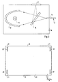
- Figure 2 shows the position sensor 3 in a schematic representation. It has a hermetically sealed, strip-shaped sensor housing 5, in which two sensor heads 6, 7 can be moved along the longitudinal extent of the sensor housing 5.
- the guides necessary for the movability are - for the sake of simplicity - not shown in FIG. 2.
- This also applies to a drive device which enables the sensor heads 6 and 7 to be positioned independently of one another.
- the mobility of the sensor heads 6 and 7 is indicated in FIG. 2 by means of the double arrows 8.
- a window 10 made of translucent material, in particular glass, is inserted into the bottom wall 9 of the sensor housing 5 and can extend over the entire length of the housing. Light rays emanating from the sensor heads 6 and 7 can pass through the window 10 and hit the printing material.
- each sensor head 6, 7 has a light transmitter and also a light receiver.
- the incoming and outgoing light rays are indicated in FIG. 2 with dashed arrow lines.
- the sensor housing 5 is included a hermetically sealed bushing 11 is provided, which is penetrated by a connecting cable 12, which comprises electrical and optical connecting lines.
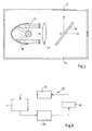
- the connecting cable 12 has an optical waveguide 13, which - according to FIG. 3 - leads to a lamp housing 14 which is hermetically sealed and houses a lighting source 15.
- the illumination source 15 generates high-intensity white light; it can be designed as a halogen or gas discharge lamp.
- a reflector 16 ′ designed as an elliptical mirror bundles the rays from the illumination source 15 and guides them to the optical waveguide 13.
- a wavelength-selective beam splitter 16 which is designed as a "semi-transparent mirror” or as an infrared cut filter (IR cut filter).
- the radiation (light rays) in the visible range passes the beam splitter; the heat radiation (IR radiation) is reflected by the beam splitter 16 and fed to an exit window 17 of the lamp housing 14, which is transparent to the heat radiation (alternatively, it is also possible for the heat radiation to pass the beam splitter and the visible light to be reflected, in which case the Positions of exit window and fiber optic are interchanged).
- the thermal energy of the illumination source 15 is dissipated to the outside, so that the inside temperature does not rise to impermissibly high values despite the hermetically sealed lamp housing 14. In this way it is possible to supply cold white light to the sensor heads 6 and 7 via the optical waveguide 13.
- the local separation of sensor housing 5 and lamp housing 14 has the advantage that only the strip-shaped sensor housing 5 has to be accommodated in the region of the printing material path of the sheet-fed printing press 1; the lamp housing 14 can be located at a less space-critical point on the sheet-fed printing press 1. Furthermore, by the training described avoided heat directly in the pressure area.
- FIG. 4 shows a plan view of the base area of a sheet 20 for the sheet-fed printing press 1. It has a sheet leading edge 18, a sheet trailing edge 19 and corner regions 21. Marks 22 (measuring marks, register marks) are arranged in the corner regions 21 of the sheet 20 and are detected by the sensor heads 6 and 7 of the position sensor 3 during printing. The two sensor heads 6 and 7 position themselves automatically in such a way that they can detect the marks 22 in an optically correct manner. Due to the transport of the sheet 20 in the printing material path of the sheet-fed printing machine 1, the marks 22 located in the area of the sheet leading edge 18 and then the marks 22 located in the area of the sheet trailing edge 19 move past the sensor heads 6 and 7.
- Register deviations with regard to the circumferential, side, narrow, wide and / or diagonal register are recognized.
- the evaluation unit 4 processes the data recorded by the position sensor 3 of existing register deviations of the individual printing units 2 and issues corresponding control commands which lead to a correction. This is done fully automatically.
- the corresponding components of the sheet-fed printing press 1 are actuated by means of suitable actuators (not shown) in order to make the register adjustments.
- a control circuit 23 is provided in order to carry out the register adjustments.
- An actual value transmitter 24 determines the register position / marks on the sheet 20.
- the actual value transmitter 24 is therefore the position sensor 3. Its data are sent to the evaluation unit 4 for a setpoint / actual value comparison, the corresponding actuators 25 (actuators, for example electric motors) ) controls.
- the actuators act on the printing process 26, the parameters of which in turn affect the Actual value transmitter 24 act. In this way, not only register deviations are registered, but also the influence of the printing material is determined, so that disturbances affecting the printing result (for example sheet lengthening, rolling out of the sheet transversely to the printing, etc.) are recognized and corrected.
- FIG. 5 shows a further exemplary embodiment of a lamp housing 14, which differs from the exemplary embodiment in FIG. 3 in that there is an imaging optic 27 between the beam splitter 16 and the reflector 16 ', which is designed as a converging lens.
- the reflector 16 ′ guides the light from the illumination source 15 with a parallel beam path to the imaging optics 27, which bundles it so that a bundled light beam can be fed to the optical waveguide 13. It is possible to couple the visible light directly into the optical waveguide or to first feed it to an exit window and then to the optical waveguide.
Landscapes
- Inking, Control Or Cleaning Of Printing Machines (AREA)
- Length Measuring Devices By Optical Means (AREA)
- Labeling Devices (AREA)
- Handling Of Sheets (AREA)
- Ticket-Dispensing Machines (AREA)
Claims (14)
- Dispositif de réglage en alignement sur une presse à imprimer à feuilles (1), comportant un détecteur optique de position, une source d'éclairement (15), une unité de traitement (4) dont les données réglantes sont envoyées aux organes réglants du dispositif de réglage, le détecteur de position (3) étant disposé, pour la saisie, qui se fait sur le matériau à imprimer (20), de l'alignement en question, dans la zone du parcours du matériau à imprimer de la presse à imprimer à feuilles,
caractérisé
par le fait que le détecteur de position (3) présente au moins deux têtes de détecteur (6, 7) situées à distance l'une de l'autre, que les têtes de détecteur (6, 7) sont disposées dans un boîtier de détecteur (5) hermétiquement fermé et que la source d'éclairement est logée dans un boîtier de lampe distinct (14) et est reliée avec les têtes de détecteur (6, 7) par l'intermédiaire d'un guide d'ondes lumineuses (13) le long du boîtier de détecteur (5). - Dispositif de réglage en alignement selon la revendication 1,
caractérisé
par le fait que les têtes de détecteur (6, 7) peuvent se déplacer indépendamment l'une de l'autre, perpendiculairement à la direction du mouvement du matériau à imprimer. - Dispositif de réglage en alignement selon l'une des revendications précédentes,
caractérisé
par le fait que le boîtier de détecteur (5) présente, pour la sortie des rayons lumineux de la source d'éclairement (15) et pour l'entrée de la lumière réfléchie par le matériau à imprimer, au moins une fenêtre (10) constituée d'un matériau transparent. - Dispositif de réglage en alignement selon l'une des revendications précédentes,
caractérisé
par le fait que les têtes de détecteur (6, 7) peuvent se déplacer au moyen d'un mécanisme d'entraînement qui se trouve à l'intérieur du boîtier de détecteur (5). - Dispositif de réglage en alignement selon l'une des revendications précédentes,
caractérisé
par le fait que le boîtier de détecteur (5) a la forme d'un barreau cylindrique ou parallélépipédique qui s'étend parallèlement au bord avant des feuilles (20) transportées sur le parcours du matériau à imprimer. - Dispositif de réglage en alignement selon l'une des revendications précédentes,
caractérisé
par le fait que la source d'éclairement (15) est conçue en tant que source de lumière blanche froide. - Dispositif de réglage en alignement selon l'une des revendications précédentes,
caractérisé
par le fait que dans le boîtier de lampe (14) est disposé un diviseur de faisceau (16) qui est situé sur le trajet des rayons de la source d'éclairement (15), agit sélectivement et sépare la lumière visible d'avec le rayonnement thermique de la source d'éclairement (15). - Dispositif de réglage en alignement selon l'une des revendications précédentes,
caractérisé
par le fait que le diviseur de faisceau (16) est un miroir sélectif à l'égard des longueurs d'onde ou un filtre d'interception des rayons infrarouges. - Dispositif de réglage en alignement selon l'une des revendications précédentes,
caractérisé
par le fait que le boîtier de lampe (14) présente une fenêtre de sortie (17) transparente au rayonnement thermique réfléchi par le diviseur de faisceau (16). - Dispositif de réglage en alignement selon l'une des revendications précédentes,
caractérisé
par le fait que dans le boîtier de lampe (14) est disposé un réflecteur (16') qui est conçu en tant que miroir elliptique et qui amène la lumière de la source d'éclairement (15), focalisée, au guide d'ondes lumineuses (13). - Dispositif de réglage en alignement selon l'une des revendications précédentes,
caractérisé
par un mécanisme de régulation dans le circuit de régulation (23) duquel le détecteur de pression (3) joue le rôle de récepteur de valeur réelle (24) et au moins un actionneur des organes de réglage joue celui d'élément réglant (25). - Dispositif de réglage en alignement selon l'une des revendications précédentes,
caractérisé
par le fait que le détecteur de position (3) établit, en fonction de la détermination de la position de marques (22) se trouvant sur le matériau à imprimer (20), des valeurs de réglage de l'alignement de l'impression, en plus serré ou en plus large, et l'envoie au moins à l'un des actionneurs correspondant aux organes de réglage, actionneur qui collabore avec un rail de bridage qui, en la bridant, intervient sur une plaque d'un cylindre de plaque. - Procédé de réglage en alignement sur des presses à imprimer à feuilles pour exécution au moyen d'un dispositif de réglage conforme à une ou plusieurs des revendications précédentes, dans lequel l'alignement respectif est saisi optiquement et mécaniquement sur le matériau à imprimer et dans lequel le résultat de la saisie est mis à profit pour le réglage mécanique automatique en alignement,
caractérisé
par le fait que, pour établir des influences du matériau à imprimer intervenant, en soi, sur le résultat de l'impression, des marques (22), disposées réparties sur la surface de fond de la feuille (20), sont saisies optiquement et leur position est traitée. - Procédé selon la revendication 13,
caractérisé
par le fait que les marques (22) sont disposées dans les zones d'angle (21) de la feuille en question (20).
Applications Claiming Priority (2)
| Application Number | Priority Date | Filing Date | Title |
|---|---|---|---|
| DE4235393 | 1992-10-21 | ||
| DE4235393A DE4235393A1 (de) | 1992-10-21 | 1992-10-21 | Registerverstelleinrichtung an einer Bogendruckmaschine sowie Verfahren zur Registerverstellung |
Publications (2)
| Publication Number | Publication Date |
|---|---|
| EP0593935A1 EP0593935A1 (fr) | 1994-04-27 |
| EP0593935B1 true EP0593935B1 (fr) | 1997-01-22 |
Family
ID=6470916
Family Applications (1)
| Application Number | Title | Priority Date | Filing Date |
|---|---|---|---|
| EP93115411A Expired - Lifetime EP0593935B1 (fr) | 1992-10-21 | 1993-09-24 | Dispositif de repérage pour une machine d'impression de feuilles, et procédé de repérage |
Country Status (5)
| Country | Link |
|---|---|
| US (1) | US5802973A (fr) |
| EP (1) | EP0593935B1 (fr) |
| JP (1) | JP3373264B2 (fr) |
| AT (1) | ATE148041T1 (fr) |
| DE (2) | DE4235393A1 (fr) |
Cited By (1)
| Publication number | Priority date | Publication date | Assignee | Title |
|---|---|---|---|---|
| DE10318571B4 (de) * | 2002-05-16 | 2015-09-10 | Heidelberger Druckmaschinen Ag | Verfahren zum Betreiben einer Register-Verstelleinrichtung in einer Offset-Druckmaschine |
Families Citing this family (32)
| Publication number | Priority date | Publication date | Assignee | Title |
|---|---|---|---|---|
| US6396070B1 (en) * | 1997-11-24 | 2002-05-28 | Datamax Corporation | Adjustable sensor assembly for printers |
| US7699550B2 (en) * | 1999-03-26 | 2010-04-20 | Datamax Corporation | Modular printer |
| US7042478B2 (en) * | 1999-03-26 | 2006-05-09 | Datamax Corporation | Modular printer |
| US7537404B2 (en) * | 1999-03-26 | 2009-05-26 | Datamax Corporation | Modular printer |
| DE10046466A1 (de) * | 1999-10-15 | 2001-04-19 | Heidelberger Druckmasch Ag | Modulares Druckmaschinensystem zum Bedrucken von Bogen |
| US7375832B2 (en) * | 2002-09-20 | 2008-05-20 | Datamax Corporation | Adjustable sensor assembly for printers |
| DE102005001193A1 (de) | 2005-01-10 | 2006-07-20 | Steinemann Technology Ag | Zylinderdruckwerk |
| US7502042B2 (en) * | 2005-05-20 | 2009-03-10 | Datamax Corporation | Laser diode thermal transfer printhead |
| TWI291415B (en) * | 2005-09-21 | 2007-12-21 | Hi Touch Imaging Tech Co Ltd | Printer capable of printing double sides of printing media |
| DE102010045036A1 (de) | 2010-09-10 | 2012-03-15 | Heidelberger Druckmaschinen Ag | Einrichtung zum Befestigen einer Druckplatte an einem Formzylinder einer Druckmaschine |
| DE102012207101B4 (de) | 2012-04-27 | 2016-06-23 | Koenig & Bauer Ag | Plattenzylinder |
| DE102012207106B4 (de) | 2012-04-27 | 2015-04-02 | Koenig & Bauer Aktiengesellschaft | Plattenzylinder |
| DE102012207109B3 (de) | 2012-04-27 | 2013-05-02 | Koenig & Bauer Aktiengesellschaft | Verfahren zum Anordnen einer Druckform auf einen Plattenzylinder |
| US8882374B2 (en) | 2012-05-25 | 2014-11-11 | Datamax—O'Neil Corporation | Printer with print frame interlock and adjustable media support |
| DE102013214784B4 (de) | 2012-08-02 | 2021-09-09 | Koenig & Bauer Ag | Vorrichtung zum Korrigieren trapezartiger Passerabweichungen |
| DE102012214585B4 (de) | 2012-08-16 | 2014-09-04 | Koenig & Bauer Aktiengesellschaft | Verfahren zum registerhaltigen Anordnen jeweils zumindest einer Druckplatte auf zumindest zwei Plattenzylindern einer Druckmaschine und ein System zur Registerregelung |
| DE102012214587B4 (de) | 2012-08-16 | 2014-05-22 | Koenig & Bauer Aktiengesellschaft | Verfahren zum Anordnen jeweils zumindest einer Druckplatte auf zumindest zwei Plattenzylindern |
| DE102012220736B4 (de) | 2012-11-14 | 2017-01-05 | Koenig & Bauer Ag | Sicherheitseinrichtung eines Plattenzylinders einer Druckmaschine und ein Verfahren zur Sicherung eines Plattenzylinders einer Druckmaschine |
| DE102012112486A1 (de) * | 2012-12-18 | 2014-06-18 | Océ Printing Systems GmbH & Co. KG | Verfahren zum Steuern eines Farbdruckers oder Farbkopierers mit Hilfe von zusätzlich aufgedruckten Positionierungsmarken |
| DE102015215539A1 (de) | 2014-09-18 | 2016-03-24 | Koenig & Bauer Ag | Vorrichtung zum Anpassen mindestens eines Zylinderaufzugs an eine Bedruckstoffänderung in einer Druckmaschine |
| DE102015215542A1 (de) | 2014-09-18 | 2016-03-24 | Koenig & Bauer Ag | Vorrichtung zum Anpassen mindestens eines Zylinderaufzugs an eine Bedruckstoffänderung in einer Druckmaschine und ein Verfahren |
| DE102015215540A1 (de) | 2014-09-18 | 2016-03-24 | Koenig & Bauer Ag | Verfahren zum Anpassen mindestens eines Druckbildes und/oder mindestens eines Zylinderaufzugs an eine Bedruckstoffänderung in einer Druckmaschine |
| DE102015200148B4 (de) | 2015-01-08 | 2017-04-13 | Koenig & Bauer Ag | Verfahren zur Anpassung mindestens einer Länge einer auf mehreren Druckbogen jeweils gleich groß drucktechnisch auszubildenden Fläche |
| DE102015204857A1 (de) * | 2015-03-18 | 2016-09-22 | Koenig & Bauer Ag | Verfahren zum Anpassen mindestens eines Druckbildes und/oder mindestens eines Zylinderaufzugs an eine Bedruckstoffänderung in einer Druckmaschine |
| DE102015017063B4 (de) | 2015-03-18 | 2022-10-27 | Koenig & Bauer Ag | Verfahren zum Anpassen eines Druckbildes und/oder mindestens eines Zylinderaufzugs an eine Bedruckstoffänderung in einer Druckmaschine |
| DE102015017062B4 (de) | 2015-03-18 | 2022-10-27 | Koenig & Bauer Ag | Verfahren zum Anpassen eines Druckbildes und/oder mindestens eines Zylinderaufzugs an eine Bedruckstoffänderung in einer Druckmaschine |
| DE102015204859A1 (de) | 2015-03-18 | 2016-09-22 | Koenig & Bauer Ag | Vorrichtung zum Anpassen eines Zylinderaufzugs an eine Bedruckstoffänderung in einer Druckmaschine |
| DE102015204855B4 (de) | 2015-03-18 | 2017-05-11 | Koenig & Bauer Ag | Verfahren zum Anpassen mindestens eines Zylinderaufzugs an eine Bedruckstoffänderung in einer Druckmaschine |
| DE102015017071B4 (de) | 2015-03-18 | 2022-10-27 | Koenig & Bauer Ag | Verfahren zum Anpassen eines Druckbildes und/oder mindestens eines Zylinderaufzugs an eine Bedruckstoffänderung in einer Druckmaschine |
| DE102015121281A1 (de) * | 2015-12-07 | 2017-07-13 | Manroland Web Systems Gmbh | Rotationsdruckmaschine |
| DE102016208945B4 (de) | 2016-05-24 | 2024-01-25 | Koenig & Bauer Ag | Zylinder einer Druckmaschine mit einer Dreheinführung |
| DE102016208943B4 (de) | 2016-05-24 | 2024-01-25 | Koenig & Bauer Ag | Zylinder einer Druckmaschine mit einer Dreheinführung |
Citations (1)
| Publication number | Priority date | Publication date | Assignee | Title |
|---|---|---|---|---|
| EP0444583A2 (fr) * | 1990-03-02 | 1991-09-04 | MAN Roland Druckmaschinen AG | Marques imprimées sur un support d'impression pour la saisie du repérage d'impression |
Family Cites Families (20)
| Publication number | Priority date | Publication date | Assignee | Title |
|---|---|---|---|---|
| DE1092485B (de) * | 1952-09-19 | 1960-11-10 | Siemens Ag | Einrichtung zum lichtelektrischen Abtasten von Registermarken einer laufenden Werkstoffbahn, insbesondere in Mehrfarben-Rotationsdruckmaschinen |
| DE1423576A1 (de) * | 1961-04-05 | 1969-01-23 | Licentia Gmbh | Verfahren zur beruehrungslosen Breitenmessung bewegter bandfoermiger Messgueter |
| GB1320898A (en) * | 1969-07-07 | 1973-06-20 | British Steel Corp | Strip measuring unit and split edge detector |
| US3832557A (en) * | 1972-05-09 | 1974-08-27 | A Bazhulin | Instrument for viewing and measuring electromagnetic radiation |
| AT337215B (de) * | 1974-10-28 | 1977-06-27 | Eltromat Tautorus & Co | Vorrichtung zum erfassen von markierungen auf einer sich bewegenden bahn, zum messen und regeln mechanischer ablaufe |
| DE2539489A1 (de) * | 1975-09-05 | 1977-03-10 | Kloeckner Werke Ag | Vorrichtung zum absaugen und verbrennen der abgase von konvertern |
| DD134743A1 (de) * | 1978-02-13 | 1979-03-21 | Arndt Jentzsch | Passmarkenauswertgeraet an mehrfarbendruckmaschinen |
| SE440204B (sv) * | 1979-04-23 | 1985-07-22 | Svecia Silkscreen Maskiner Ab | Sett och anordning att injustera ett tryck pa ett material |
| DD227096A1 (de) * | 1984-10-05 | 1985-09-11 | Polygraph Leipzig | Einrichtung zur registerkontrolle und -verstellung |
| CH665999A5 (fr) * | 1986-03-17 | 1988-06-30 | Bobst Sa | Procede et dispositif pour commander le reglage des organes d'une machine pour les arts graphiques et le cartonnage. |
| DE3713279C2 (de) * | 1987-04-18 | 1994-01-20 | Laser Sorter Gmbh | Verfahren zum Erfassen von Dimensionsfehlern und/oder dem Verzug von Papierbahnen oder Formatpapieren |
| GB8710021D0 (en) * | 1987-04-28 | 1987-06-03 | Crosfield Electronics Ltd | Monitoring passage of marks on web |
| DE3719766A1 (de) * | 1987-06-13 | 1988-12-22 | Heidelberger Druckmasch Ag | Registermesssystem |
| DE3800877A1 (de) * | 1988-01-14 | 1989-07-27 | Man Technologie Gmbh | Verfahren zum messen von dublierverschiebungen |
| DE3811359C2 (de) * | 1988-04-02 | 1994-06-16 | Heidelberger Druckmasch Ag | Vorrichtung zur Positionierung eines Meßkopfes für Passerabweichungen beim Offsetdruck |
| JPH02114106A (ja) * | 1988-10-24 | 1990-04-26 | Fuji Photo Film Co Ltd | シート材の測長装置 |
| CH679990A5 (fr) * | 1989-06-08 | 1992-05-29 | Bobst Sa | |
| GB8917102D0 (en) * | 1989-07-26 | 1989-09-13 | Tecflex Ltd | Optical alignment means |
| US4984458A (en) * | 1989-10-06 | 1991-01-15 | A.M. International, Inc. | System for measuring the relaxed length of a moving web |
| DE4107105A1 (de) * | 1991-03-06 | 1992-09-10 | Planeta Druckmaschinenwerk Ag | Passerregelung an bogendruckmaschinen |
-
1992
- 1992-10-21 DE DE4235393A patent/DE4235393A1/de not_active Withdrawn
-
1993
- 1993-09-24 DE DE59305231T patent/DE59305231D1/de not_active Expired - Lifetime
- 1993-09-24 AT AT93115411T patent/ATE148041T1/de not_active IP Right Cessation
- 1993-09-24 EP EP93115411A patent/EP0593935B1/fr not_active Expired - Lifetime
- 1993-10-19 JP JP26122593A patent/JP3373264B2/ja not_active Expired - Lifetime
-
1995
- 1995-10-12 US US08/542,298 patent/US5802973A/en not_active Expired - Lifetime
Patent Citations (1)
| Publication number | Priority date | Publication date | Assignee | Title |
|---|---|---|---|---|
| EP0444583A2 (fr) * | 1990-03-02 | 1991-09-04 | MAN Roland Druckmaschinen AG | Marques imprimées sur un support d'impression pour la saisie du repérage d'impression |
Cited By (1)
| Publication number | Priority date | Publication date | Assignee | Title |
|---|---|---|---|---|
| DE10318571B4 (de) * | 2002-05-16 | 2015-09-10 | Heidelberger Druckmaschinen Ag | Verfahren zum Betreiben einer Register-Verstelleinrichtung in einer Offset-Druckmaschine |
Also Published As
| Publication number | Publication date |
|---|---|
| JPH06206309A (ja) | 1994-07-26 |
| JP3373264B2 (ja) | 2003-02-04 |
| DE59305231D1 (de) | 1997-03-06 |
| DE4235393A1 (de) | 1994-04-28 |
| ATE148041T1 (de) | 1997-02-15 |
| EP0593935A1 (fr) | 1994-04-27 |
| US5802973A (en) | 1998-09-08 |
Similar Documents
| Publication | Publication Date | Title |
|---|---|---|
| EP0593935B1 (fr) | Dispositif de repérage pour une machine d'impression de feuilles, et procédé de repérage | |
| EP0884181B1 (fr) | Procédé de regulation des operations effectuées par une machine d'impression | |
| DE69412281T2 (de) | Ausrichtsysteme | |
| EP0713447B1 (fr) | Dispositif de verification d'image d'un produit imprime | |
| DE2925752C2 (de) | Mehrfach-Informationsaufzeichnungsgerät | |
| EP1511629B1 (fr) | Procede et dispositif pour positionner un substrat a imprimer | |
| DE3789847T2 (de) | Vorrichtung zum Zuführen und Überwachen von Streifen. | |
| DE10127249B4 (de) | Verfahren zum Ermitteln einer Position eines Druckbildes und Überwachungseinrichtung für eine Druckmaschine | |
| EP0357987A2 (fr) | Procédé de contrôle et/ou de commande du mouillage dans une machine d'impression offset | |
| DE3908270C2 (de) | Verfahren zur Steuerung eines auf einer Offset-Druckmaschine durchzuführenden Druckauftrages und Anordnung zu dessen Durchführung | |
| AT391447B (de) | Verfahren zur ermittlung der flaechendeckung einer druckvorlage oder druckplatte fuer druckmaschinen und vorrichtung zur durchfuehrung des verfahrens | |
| DE2950606A1 (de) | Vorrichtung zur zonenweisen optoelektronischen messung der flaechendeckung einer druckvorlage | |
| EP1714786B1 (fr) | Dispositif pour l'inspection de produits imprimés | |
| EP1030782B1 (fr) | Procede et dispositif pour transporter un support d'enregistrement en forme de bande pre-imprimee dans une imprimante | |
| DE69704981T2 (de) | Bildaufzeichnungssystem | |
| DE19749596C1 (de) | Verfahren und Vorrichtung zur Steuerung eines traktorlosen Aufzeichnungsträger-Antriebes in einem elektrografischen Drucker | |
| DE3521514A1 (de) | Bildinformation-lesevorrichtung | |
| DE69226568T2 (de) | Photographischer Filmträger und Verfahren zur Positionierung eines Bildfeldes | |
| DE3141758A1 (de) | Kalibriersystem fuer eine druckplatten-bildmusterbereich-messvorrichtung | |
| DE19617122A1 (de) | Verfahren und Vorrichtung zum Kalibrieren eines horizontalen Startpunktes eines Dokumentes auf einem Flachbettscanner | |
| EP1279919A1 (fr) | Appareil pour détécter la position du bord d'un produit | |
| DE69310190T2 (de) | Vorrichtung zur qualitätskontrolle eines mit einer druckmaschine hergestellten druckbildes | |
| WO1981000083A1 (fr) | Procede et dispositif pour la determination des valeurs de consigne permettant en particulier le controle automatique d'imprimeuses | |
| EP3312595A1 (fr) | Procédé et dispositif de compensation de l'effet de différence de résistance des bandes de matériau durant une inspection de bandes de matériau | |
| EP0518104A1 (fr) | Procédé et dispositif pour mesurer la densité pour des zones limitées des originaux photographiques |
Legal Events
| Date | Code | Title | Description |
|---|---|---|---|
| PUAI | Public reference made under article 153(3) epc to a published international application that has entered the european phase |
Free format text: ORIGINAL CODE: 0009012 |
|
| 17P | Request for examination filed |
Effective date: 19930924 |
|
| AK | Designated contracting states |
Kind code of ref document: A1 Designated state(s): AT CH DE FR GB LI |
|
| GBC | Gb: translation of claims filed (gb section 78(7)/1977) | ||
| 17Q | First examination report despatched |
Effective date: 19950908 |
|
| GRAG | Despatch of communication of intention to grant |
Free format text: ORIGINAL CODE: EPIDOS AGRA |
|
| GRAH | Despatch of communication of intention to grant a patent |
Free format text: ORIGINAL CODE: EPIDOS IGRA |
|
| GRAH | Despatch of communication of intention to grant a patent |
Free format text: ORIGINAL CODE: EPIDOS IGRA |
|
| GRAA | (expected) grant |
Free format text: ORIGINAL CODE: 0009210 |
|
| AK | Designated contracting states |
Kind code of ref document: B1 Designated state(s): AT CH DE FR GB LI |
|
| REF | Corresponds to: |
Ref document number: 148041 Country of ref document: AT Date of ref document: 19970215 Kind code of ref document: T |
|
| REG | Reference to a national code |
Ref country code: CH Ref legal event code: EP |
|
| REF | Corresponds to: |
Ref document number: 59305231 Country of ref document: DE Date of ref document: 19970306 |
|
| REG | Reference to a national code |
Ref country code: CH Ref legal event code: NV Representative=s name: KIRKER & CIE SA |
|
| ET | Fr: translation filed | ||
| GBT | Gb: translation of ep patent filed (gb section 77(6)(a)/1977) |
Effective date: 19970408 |
|
| PLBE | No opposition filed within time limit |
Free format text: ORIGINAL CODE: 0009261 |
|
| 26N | No opposition filed | ||
| PGFP | Annual fee paid to national office [announced via postgrant information from national office to epo] |
Ref country code: AT Payment date: 20000919 Year of fee payment: 8 |
|
| PG25 | Lapsed in a contracting state [announced via postgrant information from national office to epo] |
Ref country code: AT Free format text: LAPSE BECAUSE OF NON-PAYMENT OF DUE FEES Effective date: 20010924 |
|
| PGFP | Annual fee paid to national office [announced via postgrant information from national office to epo] |
Ref country code: CH Payment date: 20011003 Year of fee payment: 9 |
|
| REG | Reference to a national code |
Ref country code: GB Ref legal event code: IF02 |
|
| PG25 | Lapsed in a contracting state [announced via postgrant information from national office to epo] |
Ref country code: LI Free format text: LAPSE BECAUSE OF NON-PAYMENT OF DUE FEES Effective date: 20020930 Ref country code: CH Free format text: LAPSE BECAUSE OF NON-PAYMENT OF DUE FEES Effective date: 20020930 |
|
| REG | Reference to a national code |
Ref country code: CH Ref legal event code: PL |
|
| PGFP | Annual fee paid to national office [announced via postgrant information from national office to epo] |
Ref country code: FR Payment date: 20031022 Year of fee payment: 11 |
|
| PGFP | Annual fee paid to national office [announced via postgrant information from national office to epo] |
Ref country code: GB Payment date: 20031027 Year of fee payment: 11 |
|
| PG25 | Lapsed in a contracting state [announced via postgrant information from national office to epo] |
Ref country code: GB Free format text: LAPSE BECAUSE OF NON-PAYMENT OF DUE FEES Effective date: 20040924 |
|
| GBPC | Gb: european patent ceased through non-payment of renewal fee |
Effective date: 20040924 |
|
| PG25 | Lapsed in a contracting state [announced via postgrant information from national office to epo] |
Ref country code: FR Free format text: LAPSE BECAUSE OF NON-PAYMENT OF DUE FEES Effective date: 20050531 |
|
| REG | Reference to a national code |
Ref country code: FR Ref legal event code: ST |
|
| PGFP | Annual fee paid to national office [announced via postgrant information from national office to epo] |
Ref country code: DE Payment date: 20121102 Year of fee payment: 20 |
|
| REG | Reference to a national code |
Ref country code: DE Ref legal event code: R071 Ref document number: 59305231 Country of ref document: DE |
|
| PG25 | Lapsed in a contracting state [announced via postgrant information from national office to epo] |
Ref country code: DE Free format text: LAPSE BECAUSE OF EXPIRATION OF PROTECTION Effective date: 20130925 |