EP0593964B1 - Blechschneidemaschine - Google Patents
Blechschneidemaschine Download PDFInfo
- Publication number
- EP0593964B1 EP0593964B1 EP93115957A EP93115957A EP0593964B1 EP 0593964 B1 EP0593964 B1 EP 0593964B1 EP 93115957 A EP93115957 A EP 93115957A EP 93115957 A EP93115957 A EP 93115957A EP 0593964 B1 EP0593964 B1 EP 0593964B1
- Authority
- EP
- European Patent Office
- Prior art keywords
- sheet metal
- cutting head
- cutting
- axis
- cutting machine
- Prior art date
- Legal status (The legal status is an assumption and is not a legal conclusion. Google has not performed a legal analysis and makes no representation as to the accuracy of the status listed.)
- Expired - Lifetime
Links
- 238000005520 cutting process Methods 0.000 title claims abstract description 74
- 239000002184 metal Substances 0.000 claims abstract description 35
- 230000005484 gravity Effects 0.000 claims abstract description 3
- 238000009966 trimming Methods 0.000 claims 1
- 241001131696 Eurystomus Species 0.000 description 10
- 238000006073 displacement reaction Methods 0.000 description 2
- 238000009415 formwork Methods 0.000 description 2
- 238000004519 manufacturing process Methods 0.000 description 2
- 238000005253 cladding Methods 0.000 description 1
- 238000009413 insulation Methods 0.000 description 1
- 238000005304 joining Methods 0.000 description 1
- 238000005096 rolling process Methods 0.000 description 1
Images

Classifications
-
- B—PERFORMING OPERATIONS; TRANSPORTING
- B26—HAND CUTTING TOOLS; CUTTING; SEVERING
- B26F—PERFORATING; PUNCHING; CUTTING-OUT; STAMPING-OUT; SEVERING BY MEANS OTHER THAN CUTTING
- B26F1/00—Perforating; Punching; Cutting-out; Stamping-out; Apparatus therefor
- B26F1/38—Cutting-out; Stamping-out
- B26F1/3806—Cutting-out; Stamping-out wherein relative movements of tool head and work during cutting have a component tangential to the work surface
- B26F1/3813—Cutting-out; Stamping-out wherein relative movements of tool head and work during cutting have a component tangential to the work surface wherein the tool head is moved in a plane parallel to the work in a coordinate system fixed with respect to the work
-
- B—PERFORMING OPERATIONS; TRANSPORTING
- B23—MACHINE TOOLS; METAL-WORKING NOT OTHERWISE PROVIDED FOR
- B23D—PLANING; SLOTTING; SHEARING; BROACHING; SAWING; FILING; SCRAPING; LIKE OPERATIONS FOR WORKING METAL BY REMOVING MATERIAL, NOT OTHERWISE PROVIDED FOR
- B23D19/00—Shearing machines or shearing devices cutting by rotary discs
- B23D19/08—Shearing machines or shearing devices cutting by rotary discs for special use, e.g. for cutting curves, for chamfering edges
-
- B—PERFORMING OPERATIONS; TRANSPORTING
- B23—MACHINE TOOLS; METAL-WORKING NOT OTHERWISE PROVIDED FOR
- B23D—PLANING; SLOTTING; SHEARING; BROACHING; SAWING; FILING; SCRAPING; LIKE OPERATIONS FOR WORKING METAL BY REMOVING MATERIAL, NOT OTHERWISE PROVIDED FOR
- B23D33/00—Accessories for shearing machines or shearing devices
- B23D33/02—Arrangements for holding, guiding, and/or feeding work during the operation
- B23D33/04—Arrangements for holding, guiding, and/or feeding work during the operation for making circular cuts
Definitions
- the present invention relates to a sheet metal cutting machine according to the preamble of claim 1.
- This sheet metal cutting machine has a work support level, one Sheet transport device along a table side of a support plane, and one that can be moved in and out of the table and around an axis pivotable or rotatable perpendicular to the support plane Cutting head, the knife and counter knife in the area of the support plane having.
- a generic Device for cutting sheet metal is already in EP-A 0 147 816 described.
- This sheet metal cutter serves to remove protruding corners and tape cracks and enables the cutting of tape segments and tape strips. This is done by means of a cut into the Sheet metal retracting pair of knives emerging from an upper and a lower circular knife, the pair of knives through a swivel drive moving on a curve becomes.
- a second pair of feed rollers in the form of a pair of pull rollers present which is the leading end of the sheet metal plate seizes and with the given by the first pair of feed rollers Feed speed pulls and the feed alone upright receives when the trailing end receives the first pair of feed rollers leaves.
- the knife and counter knife of the cutting head form two free running circular knives. The active cutting force is primarily from applied to the rollers.
- the described genus is used for the production or for cutting thin sheet shapes, like for example for the production of Insulating formwork with a wide variety of room shapes are used.
- the insulating cladding on themselves, but much more the individual cuts for the Structure of arches, calottes, sockets, cone shapes etc. have an enormous variety of shapes, but can be determined relatively precisely geometrically.
- over the program can be cut using a program-controlled cutting head done exactly and very quickly.
- the program control controls and coordinates all essentials Movements.
- the disadvantage of this machine is that the length of the sheet metal to be cut in Feed direction must be greater than the distance between the two pairs of feed rollers.
- the sheet thickness is also through the alternating pulling, pushing feed device relatively limited.
- this is Disadvantage achieved by omitting the pairs of feed rollers.
- the feed is by a side of the support level Transport device which is longitudinally displaceable in the feed direction causes the sheet metal plate for the Cutting process is attached.
- the cutting head is equipped with punch cut knives, but what the disadvantage of a comparatively large Noise development during the cutting of the sheet metal plate Has.
- the present invention has for its object a Sheet metal cutting machine of the type mentioned at the beginning improve that they are also short in the feed direction Sheet metal plates with high performance precise and low noise can cut.
- this object is achieved by the characterizing Features of claim 1 solved. It arises thereby a real cooperation between the sheet transport device on the one hand and the circular knife, there the active cutting force is not due to tensile and impact forces of feed rollers and not by one punch-like cutting head must be applied.
- the invention allows a number of particularly advantageous Configurations. Both knives are preferred designed as a driven circular knife. So that can Advantages of the two solutions mentioned in the introduction combined can be optimally utilized by using even the shortest sheets and can be cut using the cutting knife work very calmly.
- the cutting head will via a remote-controlled drive, preferably across the table side slidably arranged. It is also possible to form a slightly inclined sliding track, so that the support for the sheet metal plate is even better.
- the cutting head and the as Feed device designed guide for each individual drive assign.
- the feed rate of the Feed device is signaled by a computer the individual drive of the cutting head in such a way controls the tangential speed of the circular knife a speed component in the feed direction has in the direction and size of the feed rate corresponds at least approximately.
- the individual drives of the circular knives are advantageously firmly arranged on the cutting head, being very special preferably the overall center of gravity of the cutting head including the individual drives at least approximately on the swivel or rotary axis of the cutting head lies.
- the Shafts of the individual drives coaxial to that in the direction of the third spatial axis oriented pivot or rotation axis aligned.
- the support level can be reduced by reducing friction Means, in particular a bristle or a Air cushions are designed as a table surface.
- FIG. 1 shows a metal sheet 1 on which shows a number of blanks A - F.
- the metal sheet 1 is by a feed unit 2, which for example a magnetic clamping device known per se may have in the direction of a Y axis for repeated Cutting operations moved forward and backward.
- a Cutting head 3 is along an X axis, preferably across the Y-axis slidably arranged.
- the Cutting head 3 a pivoting respectively Rotatability on, so that according to its own axis 4 Arrow 5 can be set in different cutting directions can.
- This well known movement game from Sheet 1 and cutting head 3 is important because thereby the cutting tools in the, for crooked cuts always changing, optimal cutting position can be brought.
- the cutting head always starts its first movement from a position S - 0 and moves according to the program, for example to a position S - 0.5 and then rotates according to arrow 5 and positions itself in the correct one Cutting direction 6 a. Since the contour to be cut out 9 is completely curved, must be coordinated with the Feed movement of the sheet 1 in the Y direction, the Cutting head constantly in the optimal cutting direction for the specific form, for example according to Set arrow 7, 8 etc. The individual cuts are rolled out after the cutting shape has been created the individual segments, etc. can be used to isolate Example a double manifold 10 can be produced.
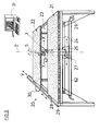
- Figure 3 is a whole work table 20, with a front work surface level 21 and a rear Working level 22, which is characterized by a medium free Working area 23 for the movement of the cutting head 3 in the X direction are interrupted, shown.
- a medium free Working area 23 for the movement of the cutting head 3 in the X direction are interrupted, shown.
- Of the Cutting head 3 can move in regardless of the displacement Turn the X direction around your own Z axis according to arrow 5.
- the displacement of the X direction of the cutting head 3 takes place via precision guides 24, on which a Carriage 25 is movable, and a remote controllable Drive motor 26 is assigned with chain exaggeration.
- the Twisting movement (arrow 5) of the cutting head 3 takes place also via a remotely controllable drive motor 27, which is mounted directly on the slide 25.
- Sheet metal transport device 29 On the left side of the table 28 is one Sheet metal transport device 29 which the sheet metal plate even by means of a program-controlled drive motor 30 moves coordinated, with all control commands from one Computer 31 are output.
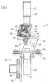
- FIG. 4 shows a preferred embodiment of the Cutting head 3 shown, both are rotating Cutting knife 40 resp. 41 by a drive motor 42 or 42 'driven. It is now essential that both drives 42, 42 'have a common axis of rotation Z, which preferably by the cutting point, designated 43, runs. Both cutting knives 40, 41 are in the form of Circular knives are trained and are related to two the Z-axis parallel gear 44 respectively. 45 driven, which each a bevel gear pair 46/47 and a Have spur gear pair 48/49. According to the optimal Inclination of the cutting disks 40, 41 are both of which Spur gear 49 driven knife shafts 50 parallel and have axes W aligned at an incline.
- the Precision guides 24 parallel guides 60 as well Guide rollers 61 on a chain hoist 62 ( Figure 3) an exact positioning of the cutting head 3 in the X direction allow.
- the cutting head 3 has one for the rotational movement Turntable 63, which in several guide wheels 64th are precision guided.
- the cutting head 3 thus has two precisely controlled movement options to your own Z axis and perpendicular to the image plane according to FIG. 4 respectively in the X direction according to FIGS. 1 and 3.
Landscapes
- Engineering & Computer Science (AREA)
- Mechanical Engineering (AREA)
- Life Sciences & Earth Sciences (AREA)
- Forests & Forestry (AREA)
- Control Of Cutting Processes (AREA)
- Mechanical Treatment Of Semiconductor (AREA)
- Shearing Machines (AREA)
- Formation And Processing Of Food Products (AREA)
- Perforating, Stamping-Out Or Severing By Means Other Than Cutting (AREA)
- Telephone Function (AREA)
Applications Claiming Priority (2)
| Application Number | Priority Date | Filing Date | Title |
|---|---|---|---|
| CH3260/92 | 1992-10-21 | ||
| CH03260/92A CH687131A5 (de) | 1992-10-21 | 1992-10-21 | Blechschneidemaschine. |
Publications (2)
| Publication Number | Publication Date |
|---|---|
| EP0593964A1 EP0593964A1 (de) | 1994-04-27 |
| EP0593964B1 true EP0593964B1 (de) | 1998-04-15 |
Family
ID=4252135
Family Applications (1)
| Application Number | Title | Priority Date | Filing Date |
|---|---|---|---|
| EP93115957A Expired - Lifetime EP0593964B1 (de) | 1992-10-21 | 1993-10-02 | Blechschneidemaschine |
Country Status (5)
| Country | Link |
|---|---|
| EP (1) | EP0593964B1 (da) |
| AT (1) | ATE165034T1 (da) |
| CH (1) | CH687131A5 (da) |
| DE (1) | DE59308403D1 (da) |
| DK (1) | DK0593964T3 (da) |
Families Citing this family (4)
| Publication number | Priority date | Publication date | Assignee | Title |
|---|---|---|---|---|
| DE19625818A1 (de) * | 1996-06-28 | 1998-01-02 | Bielomatik Leuze & Co | Vorrichtung und Verfahren zur Bearbeitung von Lagenmaterial |
| DE19913087C2 (de) * | 1999-03-23 | 2002-11-07 | Bayerische Motoren Werke Ag | Antriebseinrichtung zum Einstellen der Winkellage verschwenkbarer Messer eines Scherschnittwerkzeuges zur Herstellung einer Platine |
| ATE294661T1 (de) * | 2000-12-04 | 2005-05-15 | Mabi Ag | Vorrichtung zur dünnblech-bearbeitung |
| CN112276204B (zh) * | 2020-10-26 | 2023-01-24 | 震宇(芜湖)实业有限公司 | 一种汽车排气管用连续切割设备 |
Family Cites Families (6)
| Publication number | Priority date | Publication date | Assignee | Title |
|---|---|---|---|---|
| DE2136267A1 (de) * | 1971-07-20 | 1973-02-01 | Matoni Gmbh | Vorrichtung zur lenkung einer schneidvorrichtung, insbesondere einer kreismesserschere |
| US4495845A (en) * | 1981-07-01 | 1985-01-29 | Ppg Industries, Inc. | Pattern cutter |
| DE3314748A1 (de) * | 1983-04-23 | 1984-10-25 | Trumpf GmbH & Co, 7257 Ditzingen | Bearbeitungsmaschine, vorzugsweise maschine zum stanzen, nibbeln, brennschneiden und dgl. |
| US4548115A (en) * | 1983-04-28 | 1985-10-22 | Usm Corporation | Positioning apparatus |
| DE3400122A1 (de) * | 1984-01-04 | 1985-07-11 | Umlauf, Norbert, 5800 Hagen | Kreismesser-ausklinkschere zum ausklinken von segmenten und streifen an metallbaendern in bandfertigungslinien |
| JPH0755467B2 (ja) * | 1987-04-23 | 1995-06-14 | 株式会社川上製作所 | 積層シ−ト材の裁断装置 |
-
1992
- 1992-10-21 CH CH03260/92A patent/CH687131A5/de not_active IP Right Cessation
-
1993
- 1993-10-02 DK DK93115957T patent/DK0593964T3/da active
- 1993-10-02 AT AT93115957T patent/ATE165034T1/de active
- 1993-10-02 DE DE59308403T patent/DE59308403D1/de not_active Expired - Lifetime
- 1993-10-02 EP EP93115957A patent/EP0593964B1/de not_active Expired - Lifetime
Also Published As
| Publication number | Publication date |
|---|---|
| ATE165034T1 (de) | 1998-05-15 |
| CH687131A5 (de) | 1996-09-30 |
| DE59308403D1 (de) | 1998-05-20 |
| EP0593964A1 (de) | 1994-04-27 |
| DK0593964T3 (da) | 1999-01-25 |
Similar Documents
| Publication | Publication Date | Title |
|---|---|---|
| DE2800902A1 (de) | Schneidmaschine zum schneiden einer mehrfach gekruemmten flaeche an einem werkstueck | |
| EP0053274B1 (de) | Verfahren und Vorrichtung zum kontinuierlichen mechanischen Abtragen von Material von Strangguss-Oberflächen | |
| DE9214430U1 (de) | Horizontalbandsäge | |
| EP0330970A2 (de) | Vorrichtung zum Positionieren von bogenförmigen Kreuzsprossenrahmenteilen und zum Fräsen von trapezförmigen Ausnehmungen in diese Rahmenteile | |
| DE2428426B2 (de) | Vorrichtung zum Stirnschleifen von versenkt arbeitenden Schneidwerkzeugen | |
| DE3345875C2 (da) | ||
| EP0593964B1 (de) | Blechschneidemaschine | |
| EP0602308B1 (de) | Vorrichtung zur Bearbeitung der Kantenränder von fortlaufend bewegten plattenförmigen Werkstücken | |
| EP0620072B1 (de) | Vorrichtung und Verfahren zur Dünnblechbearbeitung | |
| DE2215740A1 (de) | Vorrichtung zum Zuführen eines Werkstückes an ein Formgebungswerkzeug | |
| CH640771A5 (de) | Verfahren zum durchtrennen von beschichtetem plattenmaterial sowie einrichtung zu seiner durchfuehrung. | |
| DE2809512A1 (de) | Drehbank | |
| EP1579965A1 (de) | Vorrichtung zum stirnseitigen Bearbeiten eines eine Negativform für einen Gerinneast eines Schachtbodengerinnes bildenden Profilstückes | |
| DE2614419B2 (de) | Sägenschärfmaschine | |
| EP3191276A1 (de) | Verfahren zur steuerung eines wandsägesystems beim erstellen eines trennschnittes | |
| DD255296B3 (de) | Verzahnmaschine mit cnc-steuerung zur herstellung von kegelraedern | |
| EP0899069B1 (de) | Verfahren und Vorrichtung zur Weiterverarbeitung von unbesäumten Rohbrettern | |
| DE3343120C1 (de) | Tunnelvortriebsmaschine mit einem mit Schneidwerkzeugen bestückten, durch einen Antrieb bewegten Werkzeugträger | |
| DE2935029B1 (de) | Verfahren zum Bewegen des oder der Brennschneidaggregate beim Brennschneiden und Vorrichtung hierfuer | |
| DE3721031C2 (da) | ||
| AT406129B (de) | Vorrichtung zum spanabhebenden bearbeiten einer streifenförmigen werkstückfläche | |
| EP0524929B1 (de) | Vorrichtung zum drehrichten von brettern | |
| DE600027C (de) | Einrichtung zum Schneiden von geraden Kanten sowie Stemm- bzw. Schweisskanten an langen Blechen | |
| DE3723764C2 (da) | ||
| DE1944565B2 (de) | Vorrichtung zum festlegen eines steines waehrend seiner bearbeitung |
Legal Events
| Date | Code | Title | Description |
|---|---|---|---|
| PUAI | Public reference made under article 153(3) epc to a published international application that has entered the european phase |
Free format text: ORIGINAL CODE: 0009012 |
|
| AK | Designated contracting states |
Kind code of ref document: A1 Designated state(s): AT BE DE DK FR IT NL |
|
| 17P | Request for examination filed |
Effective date: 19941004 |
|
| 17Q | First examination report despatched |
Effective date: 19970123 |
|
| GRAG | Despatch of communication of intention to grant |
Free format text: ORIGINAL CODE: EPIDOS AGRA |
|
| GRAG | Despatch of communication of intention to grant |
Free format text: ORIGINAL CODE: EPIDOS AGRA |
|
| GRAH | Despatch of communication of intention to grant a patent |
Free format text: ORIGINAL CODE: EPIDOS IGRA |
|
| GRAH | Despatch of communication of intention to grant a patent |
Free format text: ORIGINAL CODE: EPIDOS IGRA |
|
| GRAA | (expected) grant |
Free format text: ORIGINAL CODE: 0009210 |
|
| AK | Designated contracting states |
Kind code of ref document: B1 Designated state(s): AT BE DE DK FR IT NL |
|
| REF | Corresponds to: |
Ref document number: 165034 Country of ref document: AT Date of ref document: 19980515 Kind code of ref document: T |
|
| REF | Corresponds to: |
Ref document number: 59308403 Country of ref document: DE Date of ref document: 19980520 |
|
| ITF | It: translation for a ep patent filed | ||
| ET | Fr: translation filed | ||
| REG | Reference to a national code |
Ref country code: DK Ref legal event code: T3 |
|
| PLBE | No opposition filed within time limit |
Free format text: ORIGINAL CODE: 0009261 |
|
| STAA | Information on the status of an ep patent application or granted ep patent |
Free format text: STATUS: NO OPPOSITION FILED WITHIN TIME LIMIT |
|
| 26N | No opposition filed | ||
| PGFP | Annual fee paid to national office [announced via postgrant information from national office to epo] |
Ref country code: DK Payment date: 20121022 Year of fee payment: 20 |
|
| PGFP | Annual fee paid to national office [announced via postgrant information from national office to epo] |
Ref country code: DE Payment date: 20121023 Year of fee payment: 20 Ref country code: FR Payment date: 20121031 Year of fee payment: 20 Ref country code: BE Payment date: 20121022 Year of fee payment: 20 |
|
| PGFP | Annual fee paid to national office [announced via postgrant information from national office to epo] |
Ref country code: IT Payment date: 20121026 Year of fee payment: 20 |
|
| PGFP | Annual fee paid to national office [announced via postgrant information from national office to epo] |
Ref country code: AT Payment date: 20121011 Year of fee payment: 20 Ref country code: NL Payment date: 20121019 Year of fee payment: 20 |
|
| REG | Reference to a national code |
Ref country code: DE Ref legal event code: R071 Ref document number: 59308403 Country of ref document: DE |
|
| REG | Reference to a national code |
Ref country code: DK Ref legal event code: EUP Effective date: 20131002 |
|
| REG | Reference to a national code |
Ref country code: NL Ref legal event code: V4 Effective date: 20131002 |
|
| BE20 | Be: patent expired |
Owner name: *MABI A.G. Effective date: 20131002 |
|
| REG | Reference to a national code |
Ref country code: AT Ref legal event code: MK07 Ref document number: 165034 Country of ref document: AT Kind code of ref document: T Effective date: 20131002 |
|
| PG25 | Lapsed in a contracting state [announced via postgrant information from national office to epo] |
Ref country code: DE Free format text: LAPSE BECAUSE OF EXPIRATION OF PROTECTION Effective date: 20131003 |