EP0594010A2 - Appareil pour contrôler les caractéristiques électrique d'un bain d'électrodéposition - Google Patents
Appareil pour contrôler les caractéristiques électrique d'un bain d'électrodéposition Download PDFInfo
- Publication number
- EP0594010A2 EP0594010A2 EP93116373A EP93116373A EP0594010A2 EP 0594010 A2 EP0594010 A2 EP 0594010A2 EP 93116373 A EP93116373 A EP 93116373A EP 93116373 A EP93116373 A EP 93116373A EP 0594010 A2 EP0594010 A2 EP 0594010A2
- Authority
- EP
- European Patent Office
- Prior art keywords
- signal
- undesirable
- desirable
- filter
- electrode
- Prior art date
- Legal status (The legal status is an assumption and is not a legal conclusion. Google has not performed a legal analysis and makes no representation as to the accuracy of the status listed.)
- Ceased
Links
- 238000007747 plating Methods 0.000 title claims abstract description 53
- 239000000203 mixture Substances 0.000 claims abstract description 16
- 238000000034 method Methods 0.000 claims description 19
- 239000002131 composite material Substances 0.000 claims description 15
- 239000003990 capacitor Substances 0.000 claims description 11
- 238000012544 monitoring process Methods 0.000 claims description 10
- 239000000523 sample Substances 0.000 claims description 8
- 238000001514 detection method Methods 0.000 claims description 7
- 230000004044 response Effects 0.000 claims description 6
- 238000001914 filtration Methods 0.000 claims description 3
- 230000003139 buffering effect Effects 0.000 claims 1
- 238000004458 analytical method Methods 0.000 abstract description 5
- 239000000463 material Substances 0.000 description 10
- 238000001228 spectrum Methods 0.000 description 10
- RYGMFSIKBFXOCR-UHFFFAOYSA-N Copper Chemical compound [Cu] RYGMFSIKBFXOCR-UHFFFAOYSA-N 0.000 description 6
- 229910052802 copper Inorganic materials 0.000 description 6
- 239000010949 copper Substances 0.000 description 6
- 238000005259 measurement Methods 0.000 description 6
- 238000000576 coating method Methods 0.000 description 5
- 230000000694 effects Effects 0.000 description 4
- 230000008569 process Effects 0.000 description 4
- 229940075397 calomel Drugs 0.000 description 3
- 239000011248 coating agent Substances 0.000 description 3
- 150000001875 compounds Chemical class 0.000 description 3
- ZOMNIUBKTOKEHS-UHFFFAOYSA-L dimercury dichloride Chemical compound Cl[Hg][Hg]Cl ZOMNIUBKTOKEHS-UHFFFAOYSA-L 0.000 description 3
- 239000012535 impurity Substances 0.000 description 3
- 229910052751 metal Inorganic materials 0.000 description 3
- 239000002184 metal Substances 0.000 description 3
- 239000002253 acid Substances 0.000 description 2
- 230000032683 aging Effects 0.000 description 2
- 239000007857 degradation product Substances 0.000 description 2
- 238000010586 diagram Methods 0.000 description 2
- 230000010363 phase shift Effects 0.000 description 2
- 229910001335 Galvanized steel Inorganic materials 0.000 description 1
- 238000009825 accumulation Methods 0.000 description 1
- 230000006978 adaptation Effects 0.000 description 1
- 230000004075 alteration Effects 0.000 description 1
- 229910052782 aluminium Inorganic materials 0.000 description 1
- XAGFODPZIPBFFR-UHFFFAOYSA-N aluminium Chemical compound [Al] XAGFODPZIPBFFR-UHFFFAOYSA-N 0.000 description 1
- 238000007743 anodising Methods 0.000 description 1
- 230000008859 change Effects 0.000 description 1
- 238000006243 chemical reaction Methods 0.000 description 1
- 239000000470 constituent Substances 0.000 description 1
- 230000001419 dependent effect Effects 0.000 description 1
- 238000011156 evaluation Methods 0.000 description 1
- 239000008397 galvanized steel Substances 0.000 description 1
- 230000003993 interaction Effects 0.000 description 1
- 238000012545 processing Methods 0.000 description 1
- 230000035939 shock Effects 0.000 description 1
- 230000003595 spectral effect Effects 0.000 description 1
- 238000010183 spectrum analysis Methods 0.000 description 1
- 239000000758 substrate Substances 0.000 description 1
- 239000011573 trace mineral Substances 0.000 description 1
- 235000013619 trace mineral Nutrition 0.000 description 1
Images


Classifications
-
- G—PHYSICS
- G01—MEASURING; TESTING
- G01N—INVESTIGATING OR ANALYSING MATERIALS BY DETERMINING THEIR CHEMICAL OR PHYSICAL PROPERTIES
- G01N27/00—Investigating or analysing materials by the use of electric, electrochemical, or magnetic means
- G01N27/26—Investigating or analysing materials by the use of electric, electrochemical, or magnetic means by investigating electrochemical variables; by using electrolysis or electrophoresis
- G01N27/416—Systems
- G01N27/49—Systems involving the determination of the current at a single specific value, or small range of values, of applied voltage for producing selective measurement of one or more particular ionic species
Definitions
- the present invention relates generally to separating low frequency and high frequency components, and more specifically to analysis and feedback from an electrode or probe located in a plating bath.
- Plating is a method of putting an outer coating on the surface of an underlying metal.
- Popular uses of plating include anodizing the outer surface of aluminum and galvanized steel, and plating copper onto electronic circuit boards.
- the above plating processes do not require ultra-accurate plating equipment, and can generally accommodate and withstand impurities which may be resident in the plating bath at the beginning of the plating process, or residual impurities, commonly referred to as degradation products.
- the characteristics of the plated surface are extremely critical, frequently being more important than the characteristics of the underlying material in some cases.
- the characteristics of plated coatings usually help determine tensile strength, solderability, brightness, ductility, or flexibility, uniformity of coating, and resistance to thermal or electrical shock. These characteristics of plated coatings are highly dependent on the composition of the plating bath from which they are deposited on an underlying substrate.
- Historical platings of copper and the like were made by inserting an electrode made of soft, pure copper into an acid bath, and passing a current through the electrode and the acid bath in order to deposit copper on a circuit board, or the like.
- the copper that was deposited was usually viewed as a dead, soft grade copper, whose thickness was determined by the current flowing through the electrode, and the amount of time the circuit board spent in the bath.
- As newer plating surfaces are desired it has become necessary to apply small amounts of trace elements, compounds, as well as mixtures of plating materials, all in pre-determined quantities, in order to obtain the characteristics of the plating surface required.
- U.S. Patent No. 4,132,605 describes one of the methods which has been used to evaluate the composition of a plating solution. The method involves the application of a DC voltage to a working electrode which is positioned in the plating solution. The voltage is gradually varied in order to pass through both the metal plating voltage range and the metal stripping voltage range. A counter electrode is also placed in the plating solution to aid in the measurements.
- This method provides a signal which is related to the plating rate and is useful in evaluating the presence and concentration of elements or compounds that assist or impede the plating process.
- a plating bath contains several different elements or compounds which affect the properties of the plated deposit. This is especially difficult when the concentration or presence of one such material affects the way another such material is deposited.
- U.S. Patent No. 4,631,116 describes a method for performing a type of spectral analysis on the contents of a plating solution. This method involves applying a gradually varying DC signal to a working electrode located in the plating bath solution. A constant frequency AC signal is superimposed on the DC voltage level. As the DC voltage level is slowly varied, the AC current of the applied AC signal is measured between the working electrode and a counter electrode which is also positioned within the plating solution. The DC voltage level is varied over a pre-determined range which includes voltages which will result in plating and stripping of the plated deposit.
- the measurement of the AC current in relation to the varying DC voltage is interpreted as an AC current spectra.
- the DC voltage level and sweep rate, as well as the AC frequency, are optimized for each of the components within the plating bath in order to properly characterize the contents of the plating bath solution.
- Analysis of the resulting current spectra is made to develop a fingerprint of the composition of the plating bath.
- Comparison of the fingerprint of a bath having a known, desirable composition which has resulted in a desirable plating coating with the fingerprint of a plating bath of unknown composition will reveal to an operator the alterations which are required in the unknown plating bath in order to match the composition of the known plating bath, and generate a desired plated surface.
- the apparatus used in the application of the method of U.S. Patent No. 4,631,116 includes a reference electrode which is essentially a standard calomel electrode, a working electrode, and a counter-electrode.
- the counter electrode is the source of the DC voltage and the AC signal superimposed on the DC voltage.
- the reference electrode or standard calomel electrode provides a reference point from which the voltage applied to the counter electrode is varied.
- the present invention sums the DC and AC input signals supplied by an external DC sweep generator and AC source and applies the combined AC and DC signal to the counter electrode of a probe through an amplifier.
- the DC component of the signal detected on the reference electrode and working electrode are fed back to the source to modify and monitor the DC component.
- the apparatus of the present invention detects the AC component of the current monitored by the working electrode and, maintaining the phase integrity of the signal, provides an accurate measure of the first and second harmonics of the AC current component.
- Fig. 1 is a block diagram showing one preferred embodiment of a voltage supply and current detection apparatus in accordance with the present invention.
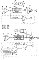
- Figs. 2a and 2b are block diagrams showing alternative preferred embodiments of the voltage supply section of the apparatus in Fig. 1.
- Fig. 3 shows an alternative embodiment of the current detection portion of the apparatus of Fig. 1.
- an alternating current (AC) source 12 which may be a waveform generator is summed with a ramp generator 14 and a direct current (DC) generator 16 by super-positioning the input signals in summer 18.
- the output of summer 18 is an AC signal which is offset by a gradually increasing DC voltage level.
- the AC signal will vary in frequency from at least 10 Hz to 10 kHz to reveal the finest structure of the current spectrum which is possible.
- the frequency may ultimately be tuned to a single, or series of discrete frequencies in order to optimally detect particular components of the plating bath.
- the AC voltage level is also varied from at least 5 millivolts to 100 millivolts in order to reveal the finest structure of the current spectrum.
- the DC sweep rate is varied from at least 1 millivolt per second to 500 millivolts per second in order to reveal the finest structure of the current spectrum.
- the DC voltage is varied from approximately 1 volt to approximately -0.2 volts with respect to the standard calomel electrode.
- the AC frequency and signal strength, as well as the DC sweep rate and DC voltage levels which are produced by embodiments of the present invention are based on the effects of the particular signals and frequencies in revealing the finest structure of the current spectrum possible.
- the working ranges selected are those specified in U.S. Patent No. 4,631,116, the contents of which are hereby incorporated by reference. It is recognized that slight or significant deviations from these parameters may be employed in order to reveal a finer spectral structure. It is also recognized that additional signals may be input to summer 18.
- the output of summer 18 passes through summer 20 and supplies the input to a power amplifier 22.
- the output of power amplifier 22 drives the counter electrode 26 of probe 24.
- Summer 20 combines the signal output by summer 18 with a feedback signal generated by reference electrode 30 and working electrode 28.
- Probe 24 is submerged in the plating tank.
- Reference electrode 30 and working electrode 28 provide a differential feedback to electrometer 32.
- Electrometer 32 behaves substantially as a differential amplifier, outputting a signal which is proportional to the difference between the reference electrode signal and the working electrode signal.
- the signal output by the electrometer is routed to a potentiostat/galvanostat selection device 34.
- a measure of the current 36 is also input to potentiostat/galvanostat select 34.
- the output of potentiostat/galvanostat select 34 is passed through summer 20 to power amplifier 22.
- Summer 20 combines the output of the potentiostat/galvanostat select 34 and summer 18, thus adding feedback from reference electrode 30 and working electrode 28 to the AC and DC signals supplied by waveform generator 12, ramp generator 14, and DC generator 16.
- Reference voltage generator 38 receives a composite signal having AC and DC components from reference electrode 30.
- the undesired AC component is filtered out of the composite signal and the desired DC component 44 routed to an external data acquisition system.
- Reference voltage generator 38 may be implemented as a high-pass filter located in parallel with an unfiltered output of the electrometer which drives a differential amplifier 42.
- the high-pass filter 40 is maintained in its phase relationship with the unfiltered output of the electrometer. The effect of this circuit is to pass the undesirable high frequency components through high-pass filter 40 and to strip out the same undesired high frequency components from the resulting signal by subtracting the output of the high-pass filter from the unfiltered signal which supplies the input to the high-pass filter. This subtraction is done by differential amplifier 42.
- the output of differential amplifier 42 thus contains the DC components and the low frequency component signals of the electrometer output. This signal is then supplied to a data acquisition system where it is digitized using a flash converter, or other analog to digital conversion device.
- phase shift or delay would result in an offset in the form of a phase delay associated with one of the inputs to differential amplifier 42. This would cause an erroneous signal to be generated by the differential amplifier which is not representative of the DC component present in the probe.
- the DC component may be ascertained as shown in Fig. 2a, in which a single, low-pass filter 84 is employed to remove the high frequency component of the electrometer output.
- FIG. 2b Yet another embodiment of a circuit for removing the high frequency component of the electrometer output is shown in Fig. 2b.
- a high-pass filter 72 drives a differential amplifier 70 in a manner similar to high-pass filter 40 driving differential amplifier 42 as shown in Fig. 1.
- An additional switching input is provided to the high-pass filter 72. This input controls a universal monolithic switched capacitor filter. Employing a switched capacitor filter allows the pass range of the high-pass filter to be adjusted during operation of the apparatus.
- the high-pass filter frequency is adjusted in proportion to waveform 76 which is representative of the signal generated by waveform generator 12.
- Waveform 76 provides an input to a frequency comparator 78 which provides a clocked output to gradually vary the frequency response of the high-pass filter. This provides a closed loop operation where the frequency cut-off of the high-pass filter can be readily controlled by the same signal which is applied to the counter-electrode 26.
- a programmable oscillator 74 can replace waveform input 76 and comparator 78 if desired.
- the programmable oscillator should be programmed to the same rate at which the waveform generator 12 sweeps through its frequency range. This ensures that the high-pass filter will have the desired frequency pass range.
- programmable oscillator 74 can be connected to ramp generator 14 if the operator desires to track the pass range of the high-pass filter in proportion to the DC voltage level.
- a switch 80 allows the operator to switch between comparator 78 and programmable oscillator 74 in controlling the frequency response of the high-pass filter through the switched capacitor filter network.
- a high-pass filter which can be used to pass the desired high frequency range onto the differential amplifier.
- Particular implementations include those which track the input frequencies, such as the universal monolithic switched capacitor filter, and others.
- a low-pass filter can be employed as shown in Fig. 2a if it does not interfere with the pure DC component of the electrometer signal.
- the signal detected by working electrode 28 is a composite signal which includes AC and DC components.
- the signal detected by working electrode 28 is also routed to a current monitor circuit. As shown in Fig. 1, the signal first passes through a current range select switch 50 and then to two parallel current sense amplifiers 52 and 56. The output of the current sense amplifier 56 is then routed to a low-pass filter which eliminates high frequency components, and maintains the phase of the output of low-pass filter 58 in phase with the input to low-pass filter 58. This ensures that the output of low-pass filter 58 is in phase with the output of current sense amplifier 52.
- the outputs of current sense amplifier 52 and the output of low-pass filter 58 drive differential amplifier 54.
- the low frequency component which is passed through the second current sense amplifier 56 and low-pass filter 58 is used to eliminate the low frequency component of the output signal by canceling the low frequency component which is passed through current sense amplifier 52.
- the output of low-pass filter 58 may also be directed to the data acquisition system, as it is representative of the DC component of the current monitoring system formed by the counter-electrode and the working electrode.
- the output of differential amplifier 54 represents the AC component 60 of the current monitor system and may be routed to a correlation filter located external to the filtering system.
- the low-pass filter 58 of Fig. 1 can be replaced by a low-pass filter 90 whose frequency pass range is determined by a universal monolithic switched capacitor filter.
- the switched capacitor filter of low-pass filter 90 is controlled in a similar manner to switched capacitor high-pass filter 72 shown in Fig. 2b.
- a waveform generator 92 drives a comparator 94 which provides a clock 98 to gradually alter the frequency response of low-pass filter 90 in proportion to the input provided by waveform 92.
- waveform 92 can be derived from waveform generator 12.
- a programmable oscillator 96 can operate in a manner similar to programmable oscillator 74 of Fig. 1, and provide a pre-determined, programmable rate of change of the switched capacitor filter of low-pass filter 90.
- Switch 98 may be manual or electronic, and allows the user or operator to select either a closed-loop mode of operation by driving the low-pass filter 90 with waveform 92, or open loop operation by driving low-pass filter 90 through programmable oscillator 96.
- the DC component of the current monitoring system 102 is output by low-pass filter 90 and is routed to a data acquisition system for further processing.
- the AC component of the current monitoring system 100 is output by differential amplifier 54 and is routed to the correlation filter.
- Output signals 102 and 100 are similar to output signals 62 and 60 of Fig. 1, respectively, but differ because of the selectable pass range of low-pass filter 90 affecting the DC component 102 and the AC component 100 of the current monitoring system.
- the apparatus and method of the present invention are particularly useful for providing accurate measurements for plating bath analysis methods previously described. However, it is not intended to limit the present invention to plating both analysis, but rather to include any system or method in which it is advantageous to separate desirable and undesirable AC signal components from a mixture thereof.
Landscapes
- Chemical & Material Sciences (AREA)
- Life Sciences & Earth Sciences (AREA)
- Health & Medical Sciences (AREA)
- Physics & Mathematics (AREA)
- Chemical Kinetics & Catalysis (AREA)
- Electrochemistry (AREA)
- Molecular Biology (AREA)
- Analytical Chemistry (AREA)
- Biochemistry (AREA)
- General Health & Medical Sciences (AREA)
- General Physics & Mathematics (AREA)
- Immunology (AREA)
- Pathology (AREA)
- Investigating Or Analyzing Materials By The Use Of Electric Means (AREA)
Applications Claiming Priority (2)
| Application Number | Priority Date | Filing Date | Title |
|---|---|---|---|
| US07/959,577 US5298145A (en) | 1992-10-13 | 1992-10-13 | Signal subtraction apparatus and method |
| US959577 | 1992-10-13 |
Publications (2)
| Publication Number | Publication Date |
|---|---|
| EP0594010A2 true EP0594010A2 (fr) | 1994-04-27 |
| EP0594010A3 EP0594010A3 (en) | 1994-08-24 |
Family
ID=25502167
Family Applications (1)
| Application Number | Title | Priority Date | Filing Date |
|---|---|---|---|
| EP9393116373A Ceased EP0594010A3 (en) | 1992-10-13 | 1993-10-08 | Apparatus for monotoring the electrical characteristics of a plating bath |
Country Status (3)
| Country | Link |
|---|---|
| US (1) | US5298145A (fr) |
| EP (1) | EP0594010A3 (fr) |
| JP (1) | JPH06201646A (fr) |
Cited By (2)
| Publication number | Priority date | Publication date | Assignee | Title |
|---|---|---|---|---|
| WO1998036270A3 (fr) * | 1997-02-12 | 1998-10-08 | Gilles Y Champagne | Procede et instrument extremement sensibles a ondes multiples mettant en application des techniques a base de voltamperemetre |
| EP0901014A1 (fr) * | 1997-09-08 | 1999-03-10 | ENDRESS + HAUSER CONDUCTA GESELLSCHAFT FÜR MESS UND REGELTECHNIK mbH & Co. | Circuit électrique pour un capteur électrochimique |
Families Citing this family (8)
| Publication number | Priority date | Publication date | Assignee | Title |
|---|---|---|---|---|
| US5644501A (en) * | 1994-12-06 | 1997-07-01 | Lin; Shengfu | Method of using a computer to collect chemical signals directly |
| AU686935B2 (en) * | 1996-04-02 | 1998-02-12 | Chih-I Lin | Method of using a computer to collect chemical signals directly |
| GB9708786D0 (en) * | 1997-05-01 | 1997-06-25 | Central Research Lab Ltd | Elecrochemical sensing circuits |
| US6264806B1 (en) | 1999-10-07 | 2001-07-24 | Technic Inc. | Plating fluid replenishment system and method |
| US20030127334A1 (en) * | 2002-01-08 | 2003-07-10 | Applied Materials, Inc. | Method for determining a concentration of conductive species in an aqueous system |
| WO2004046707A1 (fr) * | 2002-11-18 | 2004-06-03 | Advanced Sensor Technologies | Reseau microscopique de detecteurs multisites a circuit de commande et d'analyse integre |
| US20070090778A1 (en) * | 2003-05-26 | 2007-04-26 | Koninklije Philips Electronics N.V. | Signal processing |
| GB2436619B (en) * | 2005-12-19 | 2010-10-06 | Toumaz Technology Ltd | Sensor circuits |
Family Cites Families (8)
| Publication number | Priority date | Publication date | Assignee | Title |
|---|---|---|---|---|
| DE2618392A1 (de) * | 1975-04-28 | 1976-11-11 | Mitsubishi Chem Ind | Voltammetrieanordnung |
| US4132605A (en) * | 1976-12-27 | 1979-01-02 | Rockwell International Corporation | Method for evaluating the quality of electroplating baths |
| US4348632A (en) * | 1980-09-15 | 1982-09-07 | International Business Machines Corporation | Servosystem operating about noise component error signal |
| JPS58120160A (ja) * | 1982-01-13 | 1983-07-16 | Toshiba Corp | 無電解メツキ反応の測定装置 |
| US4725339A (en) * | 1984-02-13 | 1988-02-16 | International Business Machines Corporation | Method for monitoring metal ion concentrations in plating baths |
| US4631116A (en) * | 1985-06-05 | 1986-12-23 | Hughes Aircraft Company | Method of monitoring trace constituents in plating baths |
| US4808930A (en) * | 1986-09-03 | 1989-02-28 | Beckman Industrial Corporation | Technique of compensating for capacitive effects in conductivity measurements |
| US4812210A (en) * | 1987-10-16 | 1989-03-14 | The United States Department Of Energy | Measuring surfactant concentration in plating solutions |
-
1992
- 1992-10-13 US US07/959,577 patent/US5298145A/en not_active Expired - Fee Related
-
1993
- 1993-10-08 EP EP9393116373A patent/EP0594010A3/en not_active Ceased
- 1993-10-13 JP JP5256184A patent/JPH06201646A/ja active Pending
Cited By (3)
| Publication number | Priority date | Publication date | Assignee | Title |
|---|---|---|---|---|
| WO1998036270A3 (fr) * | 1997-02-12 | 1998-10-08 | Gilles Y Champagne | Procede et instrument extremement sensibles a ondes multiples mettant en application des techniques a base de voltamperemetre |
| US5980708A (en) * | 1997-02-12 | 1999-11-09 | Champagne; Gilles Y. | High sensitivity multiple waveform voltammetric instrument |
| EP0901014A1 (fr) * | 1997-09-08 | 1999-03-10 | ENDRESS + HAUSER CONDUCTA GESELLSCHAFT FÜR MESS UND REGELTECHNIK mbH & Co. | Circuit électrique pour un capteur électrochimique |
Also Published As
| Publication number | Publication date |
|---|---|
| EP0594010A3 (en) | 1994-08-24 |
| US5298145A (en) | 1994-03-29 |
| JPH06201646A (ja) | 1994-07-22 |
Similar Documents
| Publication | Publication Date | Title |
|---|---|---|
| US5298145A (en) | Signal subtraction apparatus and method | |
| US5180968A (en) | Method and apparatus for compensation of double layer charging current in electrochemical cells | |
| EP0347717B1 (fr) | Circuit de vérification de l'existence d'un plasma | |
| JPH0215634B2 (fr) | ||
| EP0597474A1 (fr) | Méthode pour contrôler sélectiviment des constituants à l'état de trace dans des bains de placage | |
| US5298132A (en) | Method for monitoring purification treatment in plating baths | |
| US5144565A (en) | Measurement of metallurgical properties in ferromagnetic test parts | |
| DE2530723C2 (de) | Einrichtung zur Messung der Phasenverschiebung in einer Anordnung gekoppelter Spulen | |
| US5320724A (en) | Method of monitoring constituents in plating baths | |
| DE69308369T2 (de) | Verfahren und Vorrichtung zum Überwachen der Qualität eines Phosphatüberzugs | |
| JP2935948B2 (ja) | 同時付着成分を含むめっきバス中の主要成分の監視方法 | |
| US2785377A (en) | Deviation factor meter | |
| US4102771A (en) | Measuring device and process for recording on electrodeposition parameters of throwing power | |
| SU846610A1 (ru) | Способ определени площади поверхностидЕТАли пРи гАльВАНООСАждЕНии | |
| SU1608422A1 (ru) | Вихретоковый способ двухпараметрового контрол изделий | |
| JP3173523B2 (ja) | 缶用材料の耐食性評価法 | |
| US8409423B2 (en) | Method for machining workpieces | |
| SU1663402A1 (ru) | Вихретоковое устройство дл измерени толщины электропровод щих покрытий | |
| JP7176983B2 (ja) | 塗膜評価装置 | |
| EP0090407A1 (fr) | Appareil et procédé pour le contrôle du placage | |
| RU2092830C1 (ru) | Микропроцессорный вольтамперометрический анализатор тяжелых металлов авс-1 | |
| SU932377A1 (ru) | Устройство дл определени качества сцеплени токопровод щего покрыти с металлической подложкой | |
| Ehrhardt | IR Drop in Electrochemical Corrosion Studies-Part 2: A Multiple Method IR Compensation | |
| SU1654384A1 (ru) | Устройство дл контрол толщины осажденного металла | |
| JP2000304789A (ja) | インピーダンス/電圧変換装置 |
Legal Events
| Date | Code | Title | Description |
|---|---|---|---|
| PUAI | Public reference made under article 153(3) epc to a published international application that has entered the european phase |
Free format text: ORIGINAL CODE: 0009012 |
|
| AK | Designated contracting states |
Kind code of ref document: A2 Designated state(s): DE FR GB NL |
|
| PUAL | Search report despatched |
Free format text: ORIGINAL CODE: 0009013 |
|
| AK | Designated contracting states |
Kind code of ref document: A3 Designated state(s): DE FR GB NL |
|
| 17P | Request for examination filed |
Effective date: 19950223 |
|
| 17Q | First examination report despatched |
Effective date: 19970505 |
|
| RAP1 | Party data changed (applicant data changed or rights of an application transferred) |
Owner name: TECHNIC, INC. |
|
| GRAG | Despatch of communication of intention to grant |
Free format text: ORIGINAL CODE: EPIDOS AGRA |
|
| STAA | Information on the status of an ep patent application or granted ep patent |
Free format text: STATUS: THE APPLICATION HAS BEEN REFUSED |
|
| 18R | Application refused |
Effective date: 19981031 |