EP0594020A1 - Installation pour chauffer de l'eau sanitaire et pour tuer de la legionella dans cette eau sanitaire - Google Patents
Installation pour chauffer de l'eau sanitaire et pour tuer de la legionella dans cette eau sanitaire Download PDFInfo
- Publication number
- EP0594020A1 EP0594020A1 EP93116412A EP93116412A EP0594020A1 EP 0594020 A1 EP0594020 A1 EP 0594020A1 EP 93116412 A EP93116412 A EP 93116412A EP 93116412 A EP93116412 A EP 93116412A EP 0594020 A1 EP0594020 A1 EP 0594020A1
- Authority
- EP
- European Patent Office
- Prior art keywords
- water
- line
- circulation
- heat exchanger
- circuit
- Prior art date
- Legal status (The legal status is an assumption and is not a legal conclusion. Google has not performed a legal analysis and makes no representation as to the accuracy of the status listed.)
- Granted
Links
Images


Classifications
-
- F—MECHANICAL ENGINEERING; LIGHTING; HEATING; WEAPONS; BLASTING
- F24—HEATING; RANGES; VENTILATING
- F24D—DOMESTIC- OR SPACE-HEATING SYSTEMS, e.g. CENTRAL HEATING SYSTEMS; DOMESTIC HOT-WATER SUPPLY SYSTEMS; ELEMENTS OR COMPONENTS THEREFOR
- F24D17/00—Domestic hot-water supply systems
- F24D17/0078—Recirculation systems
-
- F—MECHANICAL ENGINEERING; LIGHTING; HEATING; WEAPONS; BLASTING
- F24—HEATING; RANGES; VENTILATING
- F24D—DOMESTIC- OR SPACE-HEATING SYSTEMS, e.g. CENTRAL HEATING SYSTEMS; DOMESTIC HOT-WATER SUPPLY SYSTEMS; ELEMENTS OR COMPONENTS THEREFOR
- F24D17/00—Domestic hot-water supply systems
- F24D17/0073—Arrangements for preventing the occurrence or proliferation of microorganisms in the water
Definitions
- the invention relates to a system for heating domestic water and for killing legionella in this domestic water with a cold water supply line to a first heat exchanger for preheating the cold water supplied and for cooling the domestic water supplied via a domestic water outflow line from a disinfection water circuit heated to disinfection temperature, the Consists of a water heater, a loading pump, a domestic water storage tank and a buffer, the buffer in the direction of delivery of the domestic water via the domestic water outlet line to the first heat exchanger and from there to the domestic water distribution line to the taps and a circulation line with a circulation pump in connection stands.
- a system of this type is known from Figures 4, 4a and 8 to 10 of DE-PS 38 40 516.
- the system described therein fulfills its function for killing Legionella and is also characterized by an energy management operation, extensive studies have meanwhile found that Legionella cannot be avoided in the circulation water circuit.
- This circulation water cycle consists essentially of the process water distribution line to the taps, a circulation pump and a process water collection line. According to the results of these investigations, the reason for the formation of legionella despite loading this circulation water circuit with already disinfected water essentially lies in the fact that when the system is filled with cold water for the first time, legionella bacteria are introduced into the circulation water circuit from which they are used conventional means of thermal disinfection cannot be eliminated.
- the invention has for its object to provide a system of the type mentioned, with which the legionella cells which have entered the circulation water circuit can either be considerably reduced or even killed while still operating in the energy industry.
- the legionella present in the circulation water circuit as a result of the initial filling or as a result of a breakdown in operation can be introduced into the disinfection water circuit when there is no water and killed there. This significantly reduces the concentration of legionella in the circulation water circuit. If the entire system is used for a long period of time, the entire circulation water can be channeled through the disinfection water circuit several times, and ultimately Legionella bacteria can be completely destroyed.
- the aforementioned first alternative solution has the advantage of requiring only one heat exchanger.
- the object on which the invention is based is achieved in connection with the generic term mentioned at the outset in that the first heat exchanger in a manner known per se via a flow connection line and a second heat exchanger with the process water distribution line to the taps via a process water Manifold, via a backflow preventer, a water flow limiter and via the second heat exchanger, a return connection line and via an access line to the charge pump via the water heater and the buffer to form an overall circuit.
- This alternative solution has several different control options due to the second heat exchanger.
- Both alternative solutions have in common that the legionella-contaminated circulation water from the service water manifold is led via a backflow preventer and a water quantity limiter in the direction of the disinfection water circuit.
- the water flow limiter ensures that only such a large amount of circulation water is led from the service water manifold to the disinfection water circuit that a safe and constant disinfection temperature is always ensured by the charge pump and the water heater and a part of the charge pump the disinfection water circuit maintained and only the excess in the domestic water storage and / or the buffer a certain amount of enthalpy to be regulated from the disinfected water Disinfection water circuit transferred to the legionella-contaminated water from the circulation water circuit and can thus be included in the disinfection process again in terms of energy management.
- the backflow preventer ensures a clear flow direction in the entire circuit.
- the delivery rate of the charge pump which goes beyond the delivery rate of the circulation pump, draws in the storage volume in the process water tank via a connection line to it and always heats it up again in the disinfection water circuit to the disinfection temperature.
- the delivery rate of the circulation pump (liters per minute) should not exceed 50% of the delivery rate of the charge pump. If the delivery capacity of the circulation pump were greater than 50% to a maximum of 100% of the charge pump, only a small part of the charge pump or the disinfection water circuit could be continuously fed into the process water storage tank, whereas the remaining amount would go directly into the Distribution circuit flows.
- the above-described suction of the process water due to the excess delivery capacity of the charge pump compared to the circulation pump means that the legionella bacteria are removed from the circulation water circuit as well the cold water network is considerably reduced by disinfection and completely killed when the tap is not used for a long time.
- the process water storage tank is also designed in a manner known per se as a reaction container, in the upper part of which there is a reaction volume as a buffer and in the lower part of which Storage volume is located.
- the buffer in the process water storage tank can be increased by one or more upstream buffers and / or the storage volume can be increased by one or more hot water storage tanks downstream in the flow direction of the charging pump.
- a cold water quantity control valve is arranged in the cold water supply line to the first heat exchanger, the second way of which is via a Intermediate line connected to the first heat exchanger and out of it via a connecting line like the third route with the access line to the domestic water storage tank.
- the cold water quantity control valve can advantageously be controlled by a temperature sensor which is arranged in the process water distribution line to the tapping points.
- the cold water quantity control valve in the cold water supply line ensures that water of a selectable, constant temperature flows into the circulation water circuit via the process water distribution line without having to increase the water temperature behind the hot water heater in the disinfection water circuit.
- the lowest permissible temperature in the disinfection water circuit immediately after the water heater is determined by the selected reaction volume of the buffer and by the expected germ concentration of the water to be heated. According to current knowledge, a disinfection temperature of + 65 ° C requires a reaction time of at least 15 minutes and a disinfection temperature of 70 ° C a reaction time of at least 4 minutes in order to be able to kill all Legionella bacteria in the disinfection water circuit.
- a safety control valve is arranged in the cold water supply line in the flow direction upstream of the cold water flow control valve, which is located near the temperature sensor in the reaction vessel
- Process water outlet line can be throttled or closed if there is a minimum temperature of the storage volume in the reaction vessel that is to be set.
- a circulation water distribution valve is arranged in the direction of flow upstream of the water quantity limiter and the backflow preventer in the process water manifold, the third way of which is either via a first bypass line with the process water -Distribution line to the tapping points or via a second bypass line and a first circulation water quantity control valve with a heating coil which is arranged in the border area between the reaction volume and the storage volume in the reaction container.
- the circulation water distribution valve for relieving the disinfection water circuit is advantageous either depending on the Disinfection temperature in the disinfection water circuit is regulated by a temperature sensor arranged between the charge pump and the storage volume or, depending on the time, by means of a timer such that the total circulation water quantity or only a part of this water is released from the circulation water circuit to the first heat exchanger and the remaining total circulation water or part quantity can be conveyed either via the first bypass line into the process water distribution line to the taps or via the second bypass line into the heating coil for renewed heating.
- the first circulation water quantity control valve in the second bypass line can advantageously be regulated as a function of a temperature sensor in the process water outflow line from the reaction vessel.
- the "hot water priority circuit" prescribed for hot water supply systems in residential construction requires that, in an advantageous development of the invention, the charge pump, the circulation pump and a heating medium pump in each case as a function of temperature sensors in the hot water outflow line, in the hot water storage tank, in the connecting line and in a heating medium line of the water heater can be switched or regulated.
- the first alternative is in the Service water manifold in the flow direction upstream of the second heat exchanger, a second circulation water quantity control valve is arranged, the first way of which is connected to the water quantity limiter, the second way of which is connected to the second heat exchanger and the third way of which is the return connection line.
- This second circulation water quantity control valve is advantageously controlled by a temperature sensor in the process water distribution line to the tapping points.
- the first heat exchanger can be acted upon by the process water outflow line and the cold water supply line either in cocurrent or in countercurrent.
- the choice of flow direction depends, among other things, on the required standard, the requirements for the constancy of the outlet temperature and the type of 1st or 2nd alternative solution.
- a number of process water distribution lines and process water collection lines, each with separate tapping points and circulation pumps, can be connected in parallel. In this case, additional water heaters can be used to run the circulation water circuits at different flow and return temperatures.
- the first and second heat exchangers are on their own or together with the or the water heaters and charge pumps as well as one or more reaction vessels of the disinfection water circuit can be combined to form a compact device.
- Such a compact device is not only very space-saving, but can also be used retrospectively in existing systems for sanitizing hot water without special specialist knowledge of the assembly personnel.
- first and / or the second heat exchanger consisting of a total of three compact partial heat exchangers, the first of which is connected to the domestic hot water outlet line at its entrance and to the domestic hot water distribution line at its outlet, the second at its Input with the cold water supply line and at its output with the access line to the hot water storage and the third partial heat exchanger with its input to the hot water collecting line and with its output to the access line to the hot water storage are connected without internal connecting lines.
- the process water distribution line with the circulation pump and the process water manifold form a distribution circuit from which one or more branch lines branch off to secondary distribution devices.
- At least one first branch line branches off from the distributor circuit and, provided with electrical trace heating, leads to individual tapping points. Due to the individually adjustable trace heating, secured temperatures preventing the increase of Legionella as well as individual tapping temperatures at the tapping points are possible without adversely affecting the circulation water circuit and the disinfection water circuit.
- At least one second branch line from the distribution circuit leads to a secondary distribution device with a high circulation capacity, the circulation heat losses via the third heat exchanger and also from a secondary distribution line to tapping points, a circulation pump, a UV radiation device and a third heat exchanger can be compensated from the distributor circuit via a hot water distributor valve.
- one or more branch lines lead from the distributor circuit to one or more self-contained, provided with tapping points and each consisting of a circulation pump, a circulation line and a fourth heat exchanger secondary circulation circuit with high circulation capacity, which via the fourth Heat exchanger with a secondary, consisting of a water heater and a reaction tank existing disinfection water circuit is connected, in which the circulation pump is also the charge pump.
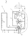
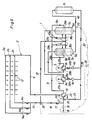
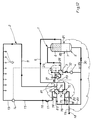
- the disinfection water circuit 1 is basically formed by a water heater 3, a charging pump 4, a domestic water storage 5 and a buffer 6, which in the present case is arranged in a manner known per se in the upper part of the domestic water storage 5, which is in this Case is also designed as a reaction container and in the lower part of which the storage volume 7 is located.
- This process water storage 5, which is also referred to below as a reaction container 5 with a buffer 6 and Storage volume 7 is designated, in the case shown, another memory 8 is arranged in series.
- the buffer 6 is connected to the first heat exchanger 10 via the process water outlet line 9 and is connected to the first heat exchanger 10 via the process water distribution line 11 to the tapping points 12 and a circulation line 13 Circulation pump 14, via a service water collecting line 15, a backflow preventer 16 and a water quantity limiter 17 with the cold water supply line 18 in connection.
- a cold water quantity control valve 20 is arranged in the cold water supply line 18.
- the cold water quantity control valve 20 is designed as a three-way valve, the first way 20a with the inflow of the cold water supply line 18, the second way 20b via an intermediate line 21 with the first heat exchanger 10 and out of this 10 via a connecting line 22 like the third way 20c with the Access line 23 to the domestic water storage 5 is connected.
- the circulation water circuit 2 is connected to the disinfection water circuit 1 to form an overall circuit 1, 2.
- the cold water quantity control valve 20 can be controlled by a temperature sensor 24 which is arranged in the process water distribution line 11 to the tapping points 12.
- the safety control valve 19 in the cold water supply line 18 is controlled by a temperature sensor 25, which is arranged in the reaction vessel 5 near the process water outflow line 9 and throttles or closes the safety control valve 19 if the required minimum temperature of the disinfection water circuit 1 Storage volume 7 is below in the reaction container 5.
- the water heater 3 in the disinfection water circuit 1 is acted upon by a heating medium line 26 with a heating medium control valve 27 which is controlled by a sensor 28 in the connecting line 29 between the water heater 3 and the domestic water storage 5.
- the delivery capacity of the charging pump 4 which goes beyond the delivery rate of the circulation pump 14, draws in and heats the storage volume 7 located in the service water store 5 via a connecting line 30 and the service water from the circulation water circuit 2 via the access line 23 it always in the disinfection water circuit 1 on the required disinfection temperature.
- the concentration of germs in the circulation water circuit 2 is considerably reduced in the event of a tapping rest and, under certain circumstances, is also completely destroyed in the event of longer tapping intervals.
- the first heat exchanger 10 consists of a total of three compact partial heat exchangers 10a, 10b and 10c, of which the first 10a is connected to the process water outlet line 9 at its entrance and to the process water distribution line 11 at its outlet, the second 10b its input with the cold water supply line 18 and at its output with the access line 23 to the hot water tank 5 and the third partial heat exchanger 10c with its input and output are connected to the access line 23 to the hot water tank 5.
- the arrows indicate the flow directions.
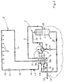
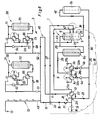
- the heating medium control valve 27 in the heating medium line 26 is controlled not only by the sensor 28 in the connecting line 29, but also by a further sensor 31 which is arranged in the process water distribution line 11.
- the cold water quantity control valve 20 of FIG. 1 is based on the exemplary embodiment of FIG. 2 the flow direction in the three partial heat exchangers 10a, 10b, 10c, the additional sensor 31 and the associated flexible control option can be dispensed with.
- a water quantity control valve 32 is also arranged between the charge pump 4 and the water heater 3, which in coordination with the water quantity limiter 17 in the process water collecting line 15 ensures that the charge pump 4 in the disinfection water circuit 1 depending on the size of the buffer 6 and the storage volume 7 circulates such a delivery rate that all germs of Legionella are killed in the process water, which leaves the buffer 6 via the process water outlet line 9 in the direction of the circulation water circuit 2.
- a circulation water distribution valve 33 is arranged in the process water flow line 15 in the flow direction upstream of the backflow preventer 16 and the water quantity limiter 17, the first path 33a and the second path 33b of which are connected to the process water collection line 15, whereas its third path 33c is connected via a first bypass line 34 to the domestic water distribution line 11 to the tapping points 12.
- This circulation water distribution valve 33 is either depending on the disinfection temperature in the disinfection water circuit 1 between the charge pump 4 and the storage volume 7 in the connecting line 30 arranged temperature sensor 35 or depending on the time controlled by a timer 36.
- This regulation is carried out in such a way that the total amount of circulation water or only a portion of this water from the circulation water circuit 2 to the first heat exchanger 10 is only released when the disinfection water circuit 1, including the service water reservoir 5, is completely heated and thus the charging capacity largely for the Circulation amount is available.
- the rest of the total circulation water or partial quantity must flow via the first bypass line 34 into the process water distribution line 11 to the tapping points 12.
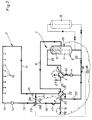
- the other embodiment according to FIG. 4 differs from that according to FIG. 3 in that the circulation water distribution valve 33 is hydromechanically connected to a heating coil 39 by its third path 33c via a second bypass line 37 and a first circulation water quantity control valve 38, which is arranged in the boundary region 40 between the buffer volume 6 and the storage volume 7 in the reaction container 5.
- the circulation water distribution valve 33 is controlled either via the temperature sensor 35 or the timer 36 such that the total amount of circulation water from the circulation water circuit 2 to the first Heat exchanger 10 is either released or can be conveyed into the heating coil 39 via the second bypass line 37.
- the charging capacity disinfection capacity
- the charge pump 4 can be switched either by a sensor 41 in the connecting line 30 and / or by a sensor 42 in the process water outlet line 9 and / or by a sensor 69 in order to meet the requirements of the process water priority circuit prescribed in residential construction.
- the first circulation water quantity control valve 38 consists of a three-way mixing valve, the first way 38a with the second bypass line 37, the second way 38b with the entry of the heating coil 39 into the hot water tank 5 and the third way 38c with the hot water Outgoing line 9 is connected.
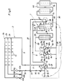
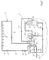
- the system according to FIG. 5 differs from the system according to FIG. 4 essentially in the following changes:
- the circulation water circuit 2 is provided with a plurality of circulation water circuits 2a, 2b and 2c connected in parallel with one another with different circulation pumps 14a, 14b and 14c and separate water quantity limiters 43a, 43b and 43c.
- the disinfection water circuit 1 contains two separate water heaters 3a and 3b, with separate heating medium control valves 27a, 27b in separate heating medium lines 26a, 26b and with separate charging pumps 4a and 4b, which are connected in parallel to one another.
- a buffer 6a is now connected upstream via the connecting line 29 and a plurality of storage volumes 7a and 7b are arranged downstream of the storage volume 7 via the connecting line 30 and two further connecting lines 44, 46.
- the buffer volume 6, 6a can only leave the disinfection water circuit 1 via the connecting line 45 if the water flowing into the process water outlet line 9 has been exposed to the required disinfection temperature and the required disinfection time.
- the storage volumes 7a and 7b which are connected to the storage volume 7 in the reaction container 5 via the connecting line 46.
- the disinfection water circuit 1 has been enlarged via the lines 30, 44 and 46 compared to the exemplary embodiment in FIG. 4.
- the first circulation water quantity control valve 38 is dependent on a temperature sensor 47 in the Process water outlet line 9 regulated from the reaction tank 5.
- the charge pump 4 or the charge pumps 4a, 4b as in the case shown in FIG. 4, each as a function of temperature sensors 41, 42 in the connecting line 30 and / or the process water outlet line 9 and / or the further temperature sensors 69 , 82 in the domestic water storage 5 and in a heating medium line 26 of the water heater 3 are switchable.
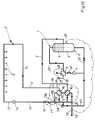
- the further exemplary embodiment in FIG. 6 differs from the system in accordance with FIG. 5 essentially in that two reaction vessels 5a and 5b with separate first circulation water quantity control valves 38a and 38b are arranged in the disinfection water circuit 1.
- Each of the reaction containers 5a and 5b contains in its upper part a reaction volume 6a, 6b as a buffer and in its lower part a storage volume 7a, 7b, which is enlarged by the downstream service water storage 7c.
- the process water distribution line 11 together with the circulation pump 14 and the process water collection line 15 each form a distribution circuit 48, from which one or more branch lines 49, 50, 51, 52 form branch secondary manifolds 53 to 56.
- the first stub 49 leads to individual tapping points 12 which are provided with electrical trace heaters 57.
- a second branch line 50 leads from the distribution circuit 48 to a secondary distribution device 54 with a high circulation capacity, the circulation water heat losses of which consist of a secondary distribution line 58 to tapping points 12, a circulation pump 59, a UV radiation device 60 and a heat exchanger 61 Heat exchangers 61 and a hot water distributor valve 62 from the distributor circuit 48 can be compensated.
- the circulation water control valve 72 is designed as a three-way valve which can be controlled via a timer 93 and the temperature sensor 73, the first route 72a with the circulation line 65, the second route 72b with the fourth heat exchanger 66 and the latter third route 72c is connected via a connecting line 90 to a connecting line 91 leading from the fourth heat exchanger 66 to the branch line 52, behind the connecting point 92 of which the temperature sensor 73 is arranged in the flow direction (see arrows).
- valve 72 can advantageously only flow as much circulation water through the connecting line 94 into the disinfection circuit 66, 67, 71, 70 in the daytime depending on the temperature sensor 73 via the path 72b as at the connecting point 92 from the lines 90 , 91 is required to ensure the target temperature at temperature sensor 73.
- the entire amount of circulation water can be passed via the connecting line 94 into the disinfection circuit 66, 67, 71, 70 and this total quantity is safely disinfected during this time until normal operation is initiated again either by switching off by the timer 93 or via a maximum flow temperature to be set on the temperature sensor 73 to the tapping points 12.
- Such a setting of the maximum temperature which is higher than the target temperature enables on the one hand a periodic reduction of any germs adhering to the inner pipe surfaces of the secondary distributor circuit 52-12 and an economical design of the fourth heat exchanger 66, since, in particular in the case of large amounts of circulation water, the difference between the inlet temperature in the Distribution circuit 52, 12, 64, 72, 92, 90 and the return temperature on the first route 72a in the circulation water control valve 72 can be very low.
- the amount of water entering the fourth heat exchanger 66 from the connecting line 94 with a temperature of, for example, 45 ° C., the amount of hot water entering the fourth heat exchanger 66 from the line 95, for example 70 ° C. can be reduced to only about 50 ° C. with an economical design Cool down to 55 ° C and thereby cause a slowly increasing temperature in the distribution circuit 52, 12, 64, 72, 90, 92 to an adjustable maximum temperature.
- the embodiment according to FIG. 9 according to the second alternative solution differs from the first alternative solution according to FIG. 1 essentially in that now the first heat exchanger 10 in a manner known per se via a flow connecting line 74 and a second heat exchanger 75 with the Process water distribution line 11 to the tapping points 12, via a circulation line 13 with circulation pump 14 and via a process water collecting line 15, via a backflow preventer 16, a water quantity limiter 17 and also via the second heat exchanger 75, a return connection line 76 and via an access line 23 the domestic water storage 5 and the buffer 6 is connected to an overall circuit 1, 2. Furthermore, in contrast to FIG. 1, the cold water supply line 18 to the first heat exchanger 10 to the process water outflow line 9 is now connected in direct current.
- the cold water preheated in the first heat exchanger 10 leaves the latter via a connecting line 77 to the access line 23.
- the main difference between the embodiment of FIG. 9 resides in the addition of a second heat exchanger 75 and the elimination of the Cold water quantity control valve 20 of FIG. 1, which is particularly suitable for smaller systems with low requirements for the constancy and level of the outlet temperature.
- a cold water quantity control valve 20 is arranged in the cold water supply line 18 and a second circulation water quantity control valve 78 is arranged in the process water collecting line 15 downstream of the water quantity limiter 17.
- the control of the cold water quantity control valve 20 takes place via the temperature sensor 24 in the process water distribution line 11 and the control of the circulation water quantity control valve 78 by a temperature sensor 79, which is likewise arranged in the process water distribution line 11.
- This system is not only characterized by an extremely varied control option via the two control valves 20 and 78, but also includes the possibility that if one of the two control valves 20, 78 fails, the other can at least partially take over the function of the other.
- FIG. 11 essentially results from a combination of the embodiment of FIG. 10 in conjunction with the circulation water quantity distribution valve 33 from FIG. 3.
- the cold water supply line 18 to the process water outlet line 9 is in direct current and in second heat exchanger 75 connected the flow connection line 74 to the process water collecting line 15 in countercurrent.
- the cold water quantity control valve 20 is arranged with its first path 20a and its second path 20b in the cold water supply line 18, on the other hand connected with its third path 20c via a connecting line 79 as a bypass to the connecting line 77.
- the circulation water quantity control valve 78 is arranged with its first path 78a and its second path 78b in the process water collecting line 15, on the other hand with its third path 78c it is connected to the return connection line 76 as a bypass via a connecting line 80.
- the circulation water quantity control valve 78 is controlled by a sensor 81 in the process water distribution line 11, which, however, is attached behind the connection of line 34 into line 11.
- the circulation water distribution valve 33 is regulated, as in the embodiment of FIG. 3, either via the sensor 35 or the timer 36.
- FIG. 12 corresponds essentially to the embodiment of FIG. 11, but with the circulation water distribution valve 33 omitted. Furthermore, a heating medium pump 83 is now arranged in the heating medium circuit 86 of the water heater 3, which pump pump jointly or separately from the charging pump 4 and the circulation pump 14 can be regulated via the temperature sensor 84 in the connecting line 30 and / or the temperature sensor 85 in the domestic water storage 5 and / or the temperature sensor 82 in the flow of the heating medium circuit 86.
- the heating medium pump 83 and the circulation pump 14 are coupled to one another, the requirements of the service water priority circuit are met via the temperature sensors 82, 84 and 85.
- the further embodiment according to FIG. 13 essentially consists of a combination of the embodiment of FIGS. 11 and 6. Accordingly, parts that correspond to it are also designated with the same reference numbers, without their function being discussed again.
- the circulation water distribution valve 33 is connected via a second bypass line 37 to the two reaction containers 5a, 5b connected in parallel to one another.
- the circulation water circuit 2 there are a total of three separate circulation water circuits 2a, 2b and 2c arranged parallel to each other.
- the first heat exchanger 10 is connected to the second heat exchanger 75 and via the cold water quantity control valve 20 and the second circulation water quantity control valve 78 according to FIG. 11.
- This embodiment is also particularly suitable for large systems with high operational safety requirements and with circulating water in e.g. three separate circulation water circuits 2a, 2b, 2c with different circulation quantities or pressure levels.
- FIG. 14 essentially results from a combination of the systems according to FIGS. 2, 3 and 12, the first and second heat exchangers 10, 75 now being combined to form a compact heat exchanger 10 similar to FIG a total of three partial heat exchangers 10a, 10b, 10c.
- the circulation water distribution valve 33 is arranged in the process water collecting line 15 as in FIG. 3 and is connected to the process water distribution line 11 via the first bypass line 34.
- the input and output of the first partial heat exchanger 10a is connected to the process water outlet line 9.
- the cold water supply line 18 leads from the safety control valve 19 via the cold water quantity control valve 20 to the inlet into the partial heat exchanger 10b, the outlet of which is connected to the access line 23 via the connecting line 89 similar to the connecting line 77 according to FIG. 13.
- the circulation water quantity control valve 78 is arranged with its two paths 78a and 78b in the process water collecting line 15 and is connected with its third path 78c via the line 87 to the entry of the partial heat exchanger 10a, from which this line via the connecting line 88 to the access line 23 is connected to the domestic water storage 5. With respect to the partial heat exchanger 10a, the partial heat exchanger 10b is connected in cocurrent and the partial heat exchanger 10c in countercurrent. Both the cold water quantity control valve 20 and the second circulation water quantity control valve 78 are regulated via the two temperature sensors 24 and 81, which are arranged in the process water distribution line 11. The circulation water distribution valve 33 is regulated, as in FIG. 11, either via the temperature sensor 35 in the connecting line 30 or via a timer 36.
- the hot water tank 8 is arranged downstream of the hot water tank 5.
- FIGS. 2 and 14 each have a compact heat exchanger 10 composed of a total of three partial heat exchangers 10a, 10b, 10c have, which can be considered both only as the first 10 or only as the second 75 or as a combination of the first and second heat exchangers 10, 75, the embodiments of FIGS. 2 and 14 represent in a way a connecting embodiment between the two alternative solutions of subsidiary claims 1 and 2.
- the circuit of the compact heat exchanger 10 is arranged in FIG. 15 with respect to the cold water quantity control valve 20 and the second circulation water quantity control valve 78 according to FIG. 14, the circulation water distribution valve 33 from FIG. 14 being omitted. Furthermore, as in FIG. 12, a heating medium pump 83 is now arranged in the heating medium circuit 86, which, like the charging pump 4 and the circulation water pump 14, can be switched via the sensors 82, 84, 85.
- FIG. 16 essentially consists of a combination of the embodiments of FIG. 15 with the embodiment of FIG. 5, parts which correspond to these figures being identified here with the same reference numerals.
- the embodiment according to FIG. 16 contains the same compact heat exchanger 10 with the cold water quantity control valve 20 and the second one 15, wherein the circulation water distribution valve 33 with the second bypass line 37 to the reaction container 5 is also arranged in the process water collecting line 15. 5, a buffer 6a is arranged upstream of this reactine container 5 and two storage volumes 7a, 7b are arranged downstream.
- This embodiment is characterized by a large buffer and storage capacity, by a plurality of circulation water circuits 2a, 2b, 2c connected in parallel with one another and by the compact heat exchanger 10 with its various control options.
- This embodiment is also suitable for large systems with both large circulation water and circulating water quantities.
- the connection and disconnection options of the circulation water circuits 2a, 2b, 2c as well as the storage volumes 7a and 7b and the upstream buffer 6a in the disinfection water circuit 1, as well as the parallel-connected charging pumps 4a and 4b with the parallel-connected water heaters 3a and 3b an extremely energy-efficient and flexible operation.
Landscapes
- Engineering & Computer Science (AREA)
- Physics & Mathematics (AREA)
- Thermal Sciences (AREA)
- Chemical & Material Sciences (AREA)
- Combustion & Propulsion (AREA)
- Mechanical Engineering (AREA)
- General Engineering & Computer Science (AREA)
- Devices For Dispensing Beverages (AREA)
- Domestic Hot-Water Supply Systems And Details Of Heating Systems (AREA)
- Physical Water Treatments (AREA)
- Heat Treatment Of Water, Waste Water Or Sewage (AREA)
Applications Claiming Priority (2)
| Application Number | Priority Date | Filing Date | Title |
|---|---|---|---|
| DE4235038A DE4235038C5 (de) | 1992-10-17 | 1992-10-17 | Anlage zum Erwärmen von Brauchwasser und zum Abtöten von Legionellen in diesem Brauchwasser |
| DE4235038 | 1992-10-17 |
Publications (2)
| Publication Number | Publication Date |
|---|---|
| EP0594020A1 true EP0594020A1 (fr) | 1994-04-27 |
| EP0594020B1 EP0594020B1 (fr) | 1996-11-27 |
Family
ID=6470694
Family Applications (1)
| Application Number | Title | Priority Date | Filing Date |
|---|---|---|---|
| EP93116412A Expired - Lifetime EP0594020B1 (fr) | 1992-10-17 | 1993-10-11 | Installation pour chauffer de l'eau sanitaire et pour tuer de la legionella dans cette eau sanitaire |
Country Status (3)
| Country | Link |
|---|---|
| EP (1) | EP0594020B1 (fr) |
| AT (1) | ATE145719T1 (fr) |
| DE (2) | DE4235038C5 (fr) |
Cited By (15)
| Publication number | Priority date | Publication date | Assignee | Title |
|---|---|---|---|---|
| WO2001063182A1 (fr) * | 2000-02-21 | 2001-08-30 | Dantaet Electronics A/S | Procede et unite de regulation des conditions bacteriennes de systemes d'eau |
| EP1156013A1 (fr) * | 2000-05-16 | 2001-11-21 | Institut Francais Du Petrole | Procédé continu de désinfection contre la légionellose dans les équipements à eau chaude sanitaire |
| WO2002012125A3 (fr) * | 2000-08-04 | 2003-01-09 | Battelle Memorial Institute | Traitement des eaux par voie thermique |
| EP1094279A3 (fr) * | 1999-10-19 | 2003-01-15 | Heatex B.V. | Traitement d'eau chauffée dans un accumulateur avec provisions anti-legionella |
| WO2003029721A1 (fr) * | 2001-09-28 | 2003-04-10 | Honeyman Water Limited | Systeme de distribution de fluide |
| NL1021713C2 (nl) * | 2002-10-22 | 2004-04-26 | Pantser Stichting | Legionella veilige installatie voor vochtverstuiving. |
| NL1024796C2 (nl) * | 2003-11-17 | 2005-05-18 | Kalsbeek Assen Holding B V A | Inrichting en werkwijze voor het pasteuriseren van aan een voorraadhouder onttrokken water. |
| WO2005056481A1 (fr) * | 2003-12-15 | 2005-06-23 | Zonca Studio Tecnico Associato | Procede et dispositif de protection totale contre les legionnelles pour des installations de distribution d'eau |
| FR2874326A1 (fr) * | 2004-08-20 | 2006-02-24 | Caleffi France Sarl | Systeme de prevention et d'eradication de la legionellose dans les installations hydrauliques de production et de distribution d'eau chaude sanitaire et dans les tours aerorefrigerentes par voie humide |
| FR2876125A1 (fr) * | 2004-10-01 | 2006-04-07 | Alfa Laval Vicarb Soc Par Acti | Dispositif de destruction de microorganismes, en particulier de legionelles, dans un reseau d'eau sanitaire ou autre |
| WO2009150153A1 (fr) * | 2008-06-09 | 2009-12-17 | Gerhard Synek Gesellschaft M.B.H. | Dispositif de désinfection |
| CN104656634A (zh) * | 2014-12-31 | 2015-05-27 | 哈尔滨工业大学 | 一种建有回流系统的供水厂效能诊断方法 |
| EP3529537A4 (fr) * | 2016-10-19 | 2020-04-22 | LegioGuard Pty Ltd | Améliorations dans des systèmes de distribution d'eau chaude, tempérée et froide |
| IT202100027374A1 (it) * | 2021-10-25 | 2023-04-25 | Ivar Spa | Dispositivo di ricircolo di un fluido, impianto di distribuzione di acqua sanitaria utilizzante detto dispositivo |
| EP4269882A1 (fr) * | 2022-04-25 | 2023-11-01 | Gebr. Kemper GmbH + Co. KG | Système d'alimentation en eau chaude avec récupération de chaleur |
Families Citing this family (13)
| Publication number | Priority date | Publication date | Assignee | Title |
|---|---|---|---|---|
| DE19508061C2 (de) * | 1995-02-23 | 1999-06-02 | Hellersdorfer Gebaeudeservice | Steuerung für eine Durchflußwarmwasserbereitungsanlage |
| DE102004001170A1 (de) * | 2004-01-07 | 2005-08-04 | Cetetherm Gmbh | Bypaß im Reaktionsspeichervorlauf |
| DE102005005091B4 (de) * | 2004-02-11 | 2011-07-28 | Dünnleder, Werner, Dipl.-Ing., 22850 | Anlage zum Erwärmen von Trinkwasser und zum Abtöten von Legionellen in diesem Trinkwasser |
| DE102005007452A1 (de) | 2005-02-18 | 2006-08-24 | Sirius 12 Gmbh | Vorrichtung zur thermischen Desinfektion von Trinkwarmwasserversorgungsanlagen |
| DE102005034021B4 (de) * | 2005-07-18 | 2007-05-16 | Rolf Schulze | Verfahren zum Erwärmen, Desinfizieren und Speichern von Trinkwasser |
| DE102007037988B4 (de) | 2007-08-10 | 2009-05-14 | Schulze, Rolf, Dipl.-Ing. | Vorrichtung zum Erwärmen, Desinfizieren und Speichern von Trinkwasser |
| DE102008016191A1 (de) | 2008-03-27 | 2009-10-01 | Schulze, Rolf, Dipl.-Ing. | Vorrichtung zum Erwärmen und Speichern von Trinkwasser |
| DE202008004421U1 (de) | 2008-04-01 | 2008-07-03 | Kesap Kessel- Und Apparatebau Gmbh | Vorrichtung zum Erwärmen von Trinkwasser |
| DE202008011719U1 (de) | 2008-09-03 | 2008-11-06 | Schulze, Rolf, Dipl.-Ing. | Vorrichtung zum Erwärmen und Speichern von Trinkwasser |
| DE102008045496B3 (de) * | 2008-09-03 | 2009-11-19 | Schulze, Rolf, Dipl.-Ing. | Vorrichtung zum Erwärmen und Speichern von Trinkwasser |
| DE102008045497B3 (de) * | 2008-09-03 | 2009-12-03 | Schulze, Rolf, Dipl.-Ing. | Vorrichtung zum Erwärmen und Speichern von Trinkwasser |
| DE102011008762B4 (de) | 2011-01-17 | 2021-04-29 | Werner Dünnleder | Anlage zum Erwärmen von Trinkwasser und zum Abtöten von Legionellen und sonstigen Keimen in dem Trinkwasser |
| DE102013015014A1 (de) | 2013-09-07 | 2015-03-12 | Gerd Haberland | Warmwasservorhaltung in Warmwasserversorgungsanlagen nach einer Zähleinrichtung |
Citations (2)
| Publication number | Priority date | Publication date | Assignee | Title |
|---|---|---|---|---|
| DE3840516A1 (de) * | 1988-12-01 | 1990-06-07 | Duennleder Werner | Brauchwasser-erwaermungsanlage mit vorrichtung zur abtoetung der legionella pneumophila |
| DE9214861U1 (de) * | 1992-11-02 | 1993-01-28 | Dünnleder, Werner, Dipl.-Ing., 2000 Norderstedt | Anlage zum Erwärmen von Brauchwasser und zum Abtöten von Legionellen in diesem Brauchwasser |
-
1992
- 1992-10-17 DE DE4235038A patent/DE4235038C5/de not_active Expired - Fee Related
-
1993
- 1993-10-11 DE DE59304604T patent/DE59304604D1/de not_active Expired - Lifetime
- 1993-10-11 AT AT93116412T patent/ATE145719T1/de not_active IP Right Cessation
- 1993-10-11 EP EP93116412A patent/EP0594020B1/fr not_active Expired - Lifetime
Patent Citations (2)
| Publication number | Priority date | Publication date | Assignee | Title |
|---|---|---|---|---|
| DE3840516A1 (de) * | 1988-12-01 | 1990-06-07 | Duennleder Werner | Brauchwasser-erwaermungsanlage mit vorrichtung zur abtoetung der legionella pneumophila |
| DE9214861U1 (de) * | 1992-11-02 | 1993-01-28 | Dünnleder, Werner, Dipl.-Ing., 2000 Norderstedt | Anlage zum Erwärmen von Brauchwasser und zum Abtöten von Legionellen in diesem Brauchwasser |
Cited By (20)
| Publication number | Priority date | Publication date | Assignee | Title |
|---|---|---|---|---|
| EP1094279A3 (fr) * | 1999-10-19 | 2003-01-15 | Heatex B.V. | Traitement d'eau chauffée dans un accumulateur avec provisions anti-legionella |
| WO2001063182A1 (fr) * | 2000-02-21 | 2001-08-30 | Dantaet Electronics A/S | Procede et unite de regulation des conditions bacteriennes de systemes d'eau |
| EP1156013A1 (fr) * | 2000-05-16 | 2001-11-21 | Institut Francais Du Petrole | Procédé continu de désinfection contre la légionellose dans les équipements à eau chaude sanitaire |
| FR2809099A1 (fr) * | 2000-05-16 | 2001-11-23 | Inst Francais Du Petrole | Procede continu curatif et preventif de desinfection et de lutte contre la legionellose dans les equipements de stockage et de production et les circuits de distribution d'eau chaude sanitaire |
| WO2002012125A3 (fr) * | 2000-08-04 | 2003-01-09 | Battelle Memorial Institute | Traitement des eaux par voie thermique |
| US7316243B2 (en) | 2001-09-28 | 2008-01-08 | Honeyman Group Limited | Fluid delivery system |
| WO2003029721A1 (fr) * | 2001-09-28 | 2003-04-10 | Honeyman Water Limited | Systeme de distribution de fluide |
| NL1021713C2 (nl) * | 2002-10-22 | 2004-04-26 | Pantser Stichting | Legionella veilige installatie voor vochtverstuiving. |
| NL1024796C2 (nl) * | 2003-11-17 | 2005-05-18 | Kalsbeek Assen Holding B V A | Inrichting en werkwijze voor het pasteuriseren van aan een voorraadhouder onttrokken water. |
| WO2005056481A1 (fr) * | 2003-12-15 | 2005-06-23 | Zonca Studio Tecnico Associato | Procede et dispositif de protection totale contre les legionnelles pour des installations de distribution d'eau |
| FR2874326A1 (fr) * | 2004-08-20 | 2006-02-24 | Caleffi France Sarl | Systeme de prevention et d'eradication de la legionellose dans les installations hydrauliques de production et de distribution d'eau chaude sanitaire et dans les tours aerorefrigerentes par voie humide |
| FR2876125A1 (fr) * | 2004-10-01 | 2006-04-07 | Alfa Laval Vicarb Soc Par Acti | Dispositif de destruction de microorganismes, en particulier de legionelles, dans un reseau d'eau sanitaire ou autre |
| WO2006037868A1 (fr) * | 2004-10-01 | 2006-04-13 | Alfa Laval Vicarb | Dispositif de destruction de microorganismes, en particulier de légionelles, dans un réseau d'eau sanitaire ou autre |
| WO2009150153A1 (fr) * | 2008-06-09 | 2009-12-17 | Gerhard Synek Gesellschaft M.B.H. | Dispositif de désinfection |
| CN104656634A (zh) * | 2014-12-31 | 2015-05-27 | 哈尔滨工业大学 | 一种建有回流系统的供水厂效能诊断方法 |
| CN104656634B (zh) * | 2014-12-31 | 2017-05-31 | 哈尔滨工业大学 | 一种建有回流系统的供水厂效能诊断方法 |
| EP3529537A4 (fr) * | 2016-10-19 | 2020-04-22 | LegioGuard Pty Ltd | Améliorations dans des systèmes de distribution d'eau chaude, tempérée et froide |
| IT202100027374A1 (it) * | 2021-10-25 | 2023-04-25 | Ivar Spa | Dispositivo di ricircolo di un fluido, impianto di distribuzione di acqua sanitaria utilizzante detto dispositivo |
| WO2023073485A1 (fr) * | 2021-10-25 | 2023-05-04 | I.V.A.R. S.P.A. | Dispositif de recirculation de fluide, système de distribution pour eau sanitaire utilisant ledit dispositif |
| EP4269882A1 (fr) * | 2022-04-25 | 2023-11-01 | Gebr. Kemper GmbH + Co. KG | Système d'alimentation en eau chaude avec récupération de chaleur |
Also Published As
| Publication number | Publication date |
|---|---|
| DE4235038C5 (de) | 2011-06-16 |
| ATE145719T1 (de) | 1996-12-15 |
| EP0594020B1 (fr) | 1996-11-27 |
| DE4235038C2 (de) | 1995-02-23 |
| DE59304604D1 (de) | 1997-01-09 |
| DE4235038A1 (de) | 1994-04-21 |
Similar Documents
| Publication | Publication Date | Title |
|---|---|---|
| EP0594020B1 (fr) | Installation pour chauffer de l'eau sanitaire et pour tuer de la legionella dans cette eau sanitaire | |
| EP0372293B1 (fr) | Installation de chauffage d'eau chaude sanitaire avec appareillage pour détruire la legionnella pneumophila | |
| EP2154436B1 (fr) | Procédé et dispositif pour l'utilisation de chaleur | |
| DE4236959C2 (de) | Anlage zum Erwärmen von Brauchwasser und zum Abtöten von Legionellen in diesem Brauchwasser | |
| EP1170554A2 (fr) | Ensemble et procédé pour préparer de l'eau chaude sanitaire | |
| DE19504730C1 (de) | Warmwasserbereitungsanlage nach dem Durchflußprinzip mit Leistungsbegrenzung | |
| EP1371910B1 (fr) | Station de raccordement domestique pour chauffage à distance | |
| DE3727442C2 (fr) | ||
| EP1553353B1 (fr) | Bypass dans un conduit d'arrivée d'un réservoir de réaction | |
| DE102006009411B4 (de) | Anlage zum Erwärmen von Trinkwasser und zum Abtöten von Legionellen und sonstigen Keimen | |
| DE10034513A1 (de) | Desinfektion des gesamten Zirkulations-Volumenstromes | |
| DE9214861U1 (de) | Anlage zum Erwärmen von Brauchwasser und zum Abtöten von Legionellen in diesem Brauchwasser | |
| DE102015118826A1 (de) | Anordnung und Verfahren zur Bereitstellung von warmem Trinkwasser mit einem Wärmeübertrager | |
| DE102005005091B4 (de) | Anlage zum Erwärmen von Trinkwasser und zum Abtöten von Legionellen in diesem Trinkwasser | |
| DE202006003226U1 (de) | Anlage zum Erwärmen von Trinkwasser und zum Abtöten von Legionellen und sonstigen Keimen | |
| AT500552B1 (de) | Trinkwasser-anlage | |
| DE202004002058U1 (de) | Anlage zum Erwärmen von Trinkwasser und zum Abtöten von Legionellen und sonstigen Keimen | |
| DE3710927C2 (fr) | ||
| DE102006033834B4 (de) | Anlage zum Erwärmen von Trinkwasser und zum Abtöten von Legionellen und sonstigen Keimen | |
| DE9214024U1 (de) | Anlage zum Erwärmen von Brauchwasser und zum Abtöten von Legionellen in diesem Brauchwasser | |
| DE8814968U1 (de) | Vorrichtung zur Brauchwasser-Erwärmung | |
| EP4269882B1 (fr) | Système d'alimentation en eau chaude avec récupération de chaleur | |
| CH687786A5 (de) | Einrichtung zur Bereitung und Verteilung von warmem Misch- und/oder Brauchwasser. | |
| DE20217305U1 (de) | Desinfektion des gesamten Zirkulations-Volumenstromes | |
| EP3647667B1 (fr) | Chauffe-eau instantané d'eau potable, système de chauffage d'eau potable et procédé de fonctionnement d'un chauffe-eau instantané d'eau potable |
Legal Events
| Date | Code | Title | Description |
|---|---|---|---|
| PUAI | Public reference made under article 153(3) epc to a published international application that has entered the european phase |
Free format text: ORIGINAL CODE: 0009012 |
|
| AK | Designated contracting states |
Kind code of ref document: A1 Designated state(s): AT CH DE ES FR GB IT LI NL SE |
|
| 17P | Request for examination filed |
Effective date: 19941018 |
|
| GRAG | Despatch of communication of intention to grant |
Free format text: ORIGINAL CODE: EPIDOS AGRA |
|
| 17Q | First examination report despatched |
Effective date: 19960201 |
|
| GRAH | Despatch of communication of intention to grant a patent |
Free format text: ORIGINAL CODE: EPIDOS IGRA |
|
| GRAH | Despatch of communication of intention to grant a patent |
Free format text: ORIGINAL CODE: EPIDOS IGRA |
|
| GRAA | (expected) grant |
Free format text: ORIGINAL CODE: 0009210 |
|
| AK | Designated contracting states |
Kind code of ref document: B1 Designated state(s): AT CH DE ES FR GB IT LI NL SE |
|
| PG25 | Lapsed in a contracting state [announced via postgrant information from national office to epo] |
Ref country code: NL Free format text: LAPSE BECAUSE OF FAILURE TO SUBMIT A TRANSLATION OF THE DESCRIPTION OR TO PAY THE FEE WITHIN THE PRESCRIBED TIME-LIMIT Effective date: 19961127 Ref country code: IT Free format text: LAPSE BECAUSE OF FAILURE TO SUBMIT A TRANSLATION OF THE DESCRIPTION OR TO PAY THE FEE WITHIN THE PRE;WARNING: LAPSES OF ITALIAN PATENTS WITH EFFECTIVE DATE BEFORE 2007 MAY HAVE OCCURRED AT ANY TIME BEFORE 2007. THE CORRECT EFFECTIVE DATE MAY BE DIFFERENT FROM THE ONE RECORDED.SCRIBED TIME-LIMIT Effective date: 19961127 Ref country code: ES Free format text: THE PATENT HAS BEEN ANNULLED BY A DECISION OF A NATIONAL AUTHORITY Effective date: 19961127 |
|
| REF | Corresponds to: |
Ref document number: 145719 Country of ref document: AT Date of ref document: 19961215 Kind code of ref document: T |
|
| REF | Corresponds to: |
Ref document number: 59304604 Country of ref document: DE Date of ref document: 19970109 |
|
| ET | Fr: translation filed | ||
| PG25 | Lapsed in a contracting state [announced via postgrant information from national office to epo] |
Ref country code: SE Effective date: 19970227 |
|
| GBT | Gb: translation of ep patent filed (gb section 77(6)(a)/1977) |
Effective date: 19970326 |
|
| NLV1 | Nl: lapsed or annulled due to failure to fulfill the requirements of art. 29p and 29m of the patents act | ||
| REG | Reference to a national code |
Ref country code: CH Ref legal event code: NV Representative=s name: E. BLUM & CO. PATENTANWAELTE |
|
| PLBE | No opposition filed within time limit |
Free format text: ORIGINAL CODE: 0009261 |
|
| STAA | Information on the status of an ep patent application or granted ep patent |
Free format text: STATUS: NO OPPOSITION FILED WITHIN TIME LIMIT |
|
| 26N | No opposition filed | ||
| PGFP | Annual fee paid to national office [announced via postgrant information from national office to epo] |
Ref country code: GB Payment date: 20011010 Year of fee payment: 9 |
|
| PGFP | Annual fee paid to national office [announced via postgrant information from national office to epo] |
Ref country code: FR Payment date: 20011012 Year of fee payment: 9 |
|
| REG | Reference to a national code |
Ref country code: GB Ref legal event code: IF02 |
|
| PG25 | Lapsed in a contracting state [announced via postgrant information from national office to epo] |
Ref country code: GB Free format text: LAPSE BECAUSE OF NON-PAYMENT OF DUE FEES Effective date: 20021011 |
|
| GBPC | Gb: european patent ceased through non-payment of renewal fee |
Effective date: 20021011 |
|
| PG25 | Lapsed in a contracting state [announced via postgrant information from national office to epo] |
Ref country code: FR Free format text: LAPSE BECAUSE OF NON-PAYMENT OF DUE FEES Effective date: 20030630 |
|
| REG | Reference to a national code |
Ref country code: FR Ref legal event code: ST |
|
| REG | Reference to a national code |
Ref country code: CH Ref legal event code: PFA Owner name: DUENNLEDER, WERNER, DIPL.-ING. Free format text: DUENNLEDER, WERNER, DIPL.-ING.#AM OCHSENZOLL 41B#D-22850 NORDERSTEDT (DE) -TRANSFER TO- DUENNLEDER, WERNER, DIPL.-ING.#AM OCHSENZOLL 41B#D-22850 NORDERSTEDT (DE) |
|
| PGFP | Annual fee paid to national office [announced via postgrant information from national office to epo] |
Ref country code: CH Payment date: 20071015 Year of fee payment: 15 Ref country code: AT Payment date: 20071015 Year of fee payment: 15 |
|
| REG | Reference to a national code |
Ref country code: CH Ref legal event code: PL |
|
| PG25 | Lapsed in a contracting state [announced via postgrant information from national office to epo] |
Ref country code: AT Free format text: LAPSE BECAUSE OF NON-PAYMENT OF DUE FEES Effective date: 20081011 |
|
| PG25 | Lapsed in a contracting state [announced via postgrant information from national office to epo] |
Ref country code: LI Free format text: LAPSE BECAUSE OF NON-PAYMENT OF DUE FEES Effective date: 20081031 Ref country code: CH Free format text: LAPSE BECAUSE OF NON-PAYMENT OF DUE FEES Effective date: 20081031 |
|
| PGFP | Annual fee paid to national office [announced via postgrant information from national office to epo] |
Ref country code: DE Payment date: 20110426 Year of fee payment: 18 |
|
| PG25 | Lapsed in a contracting state [announced via postgrant information from national office to epo] |
Ref country code: DE Free format text: LAPSE BECAUSE OF NON-PAYMENT OF DUE FEES Effective date: 20130501 |
|
| REG | Reference to a national code |
Ref country code: DE Ref legal event code: R119 Ref document number: 59304604 Country of ref document: DE Effective date: 20130501 |