EP0594031A1 - Elément électrique d'inductance - Google Patents
Elément électrique d'inductance Download PDFInfo
- Publication number
- EP0594031A1 EP0594031A1 EP93116457A EP93116457A EP0594031A1 EP 0594031 A1 EP0594031 A1 EP 0594031A1 EP 93116457 A EP93116457 A EP 93116457A EP 93116457 A EP93116457 A EP 93116457A EP 0594031 A1 EP0594031 A1 EP 0594031A1
- Authority
- EP
- European Patent Office
- Prior art keywords
- legs
- contact pin
- magnetic core
- opposite sides
- pushed
- Prior art date
- Legal status (The legal status is an assumption and is not a legal conclusion. Google has not performed a legal analysis and makes no representation as to the accuracy of the status listed.)
- Granted
Links
- 230000001939 inductive effect Effects 0.000 claims description 7
- 238000004804 winding Methods 0.000 claims description 2
- 241000237858 Gastropoda Species 0.000 description 5
- 229910000859 α-Fe Inorganic materials 0.000 description 3
- 230000006978 adaptation Effects 0.000 description 1
- 230000002411 adverse Effects 0.000 description 1
- 230000006735 deficit Effects 0.000 description 1
- 230000001419 dependent effect Effects 0.000 description 1
- 238000011161 development Methods 0.000 description 1
- 230000018109 developmental process Effects 0.000 description 1
Images
Classifications
-
- H—ELECTRICITY
- H01—ELECTRIC ELEMENTS
- H01F—MAGNETS; INDUCTANCES; TRANSFORMERS; SELECTION OF MATERIALS FOR THEIR MAGNETIC PROPERTIES
- H01F27/00—Details of transformers or inductances, in general
- H01F27/28—Coils; Windings; Conductive connections
- H01F27/29—Terminals; Tapping arrangements for signal inductances
-
- H—ELECTRICITY
- H01—ELECTRIC ELEMENTS
- H01F—MAGNETS; INDUCTANCES; TRANSFORMERS; SELECTION OF MATERIALS FOR THEIR MAGNETIC PROPERTIES
- H01F17/00—Fixed inductances of the signal type
- H01F17/04—Fixed inductances of the signal type with magnetic core
- H01F17/041—Means for preventing rotation or displacement of the core
-
- H—ELECTRICITY
- H01—ELECTRIC ELEMENTS
- H01F—MAGNETS; INDUCTANCES; TRANSFORMERS; SELECTION OF MATERIALS FOR THEIR MAGNETIC PROPERTIES
- H01F5/00—Coils
- H01F5/04—Arrangements of electric connections to coils, e.g. leads
- H01F2005/043—Arrangements of electric connections to coils, e.g. leads having multiple pin terminals, e.g. arranged in two parallel lines at both sides of the coil
-
- H—ELECTRICITY
- H01—ELECTRIC ELEMENTS
- H01F—MAGNETS; INDUCTANCES; TRANSFORMERS; SELECTION OF MATERIALS FOR THEIR MAGNETIC PROPERTIES
- H01F5/00—Coils
- H01F5/04—Arrangements of electric connections to coils, e.g. leads
- H01F2005/046—Details of formers and pin terminals related to mounting on printed circuits
Definitions
- the present invention relates to an inductive electrical component according to the preamble of patent claim 1.
- Such inductive components are known, for example, from the Siemens data book 1990/91 "Ferrites and Accessories", in particular pages 321 to 323 and 338 and 339.
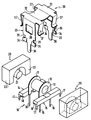
- a coil former 10 has a winding space delimited by two coil former flanges 11, 12 with a cylindrical through hole 13 for receiving central slugs 21 from EP core halves 20 to be described later.
- the coil former 10 also has two integrally molded contact pin strips 14, 15 with contact pins 16.
- Two EP core halves 20 with central slugs 21 and core legs 22 can be slid onto the bobbin 10 in such a way that the central slugs 21 engage in the cylindrical through hole 13 and the core legs 22 rest on the contact pin strips 14, 15.
- the transformer design in question is generally known, for which purpose, for example, the representation on the page 323 of the above-mentioned Siemens data book.
- the core halves are held on the coil body by means of a holding device, which is formed by two separate parts, namely a bracket and a clamp.
- a holding device which is formed by two separate parts, namely a bracket and a clamp.
- both the bracket and the bracket are U-shaped.
- the bracket on the outside of the two legs of the U-shape each has a locking lug, while the clip in the legs of the U-shape each has a recess adapted to the locking lugs of the bracket.
- the bracket and the clip are pushed from one side in the direction of the central axis from the bobbin through-hole and central slug of the core halves onto the assembled unit of coil bobbin and core halves, the latching lugs of the bracket then latching into the recesses in the clip. Since the yoke of the clip is concave and thus exerts an additional spring action, the core halves are pushed together and held on the coil body in the direction of the above-mentioned axis.
- the bracket seated on a core half has two inwardly directed legs engaging the core half, which ensure a certain mounting perpendicular to the aforementioned axis (also the magnetic axis of the transmitter).
- an embodiment of the type explained above is not yet completely satisfactory with regard to the holding of the core halves on the coil former in that a good holding device is provided by the bracket and the clamp Direction of the magnetic axis but not always sufficient support perpendicular to this axis is guaranteed, so that the core halves can still have some play on the coil former, which can adversely affect the electromagnetic properties of the transmitter.
- FIG. 1 Another known embodiment of a typical transformer design has a so-called Q-core in the form of two core halves, this design generally corresponding in terms of the coil form and the ferrite core to the design with EP core explained above.
- a cover cap is provided which, when the core halves are attached to the coil former, is pushed onto this unit comprising the coil former and core from above.
- the cover cap In the direction of the magnetic axis, the cover cap has two resilient legs on opposite sides, which act on the outer sides of the core halves and compress them on the coil body in the direction of the magnetic axis.
- the core halves may not be adequately fastened perpendicularly to the magnetic axis on the coil former.
- the present invention has for its object to provide an inductive electrical component of the type in question a way to adequately attach the magnetic core on the bobbin both in the magnetic axis and perpendicular to it.
- a spring cap 30 designed according to the invention is provided in connection with a special design of the contact pin strips 14, 15 of the coil body 10 adapted to this.
- the spring cap 30 has a yoke 31 which is concave at least in its central region 32 and thereby receives an additional spring action.
- legs 33 are provided on two opposite sides, which have locking lugs 34, which are preferably inclined outward from the surface of the legs 33. These locking lugs 34 are formed in that the legs 33 have incisions 35 in the region of their free ends with the dimensions of the contact pin strips 14, 15 of the coil body Have 10 corresponding dimensions. The legs 33 continue beyond the locking lugs 34 in earthing pins 36.
- spring clips 37 are provided on the yoke 31.
- the coil former 10 has, in adaptation to the latching lugs 34 of the spring cap 30 at the free ends of the contact pin strips 14, 15, undercuts 18 delimited to the outside by projections 17.
- the locking lugs 34 snap into the undercuts 18, whereby the core halves 20 are held on the bobbin 10 in the direction perpendicular to the magnetic axis, that is to say the central axis running through the through hole 13 and the central slugs 21.
- the core halves 20 are held together by the spring clip 37. In this way, the core halves 20 are held firmly in two mutually perpendicular directions without play on the coil body 10, so that impairments to the electromagnetic properties of the inductive component can no longer occur.
- recesses 38 are provided in the legs 33 of the spring cap 30 via which the spring cap 30 can be glued to the core halves 20.
Landscapes
- Engineering & Computer Science (AREA)
- Power Engineering (AREA)
- Microelectronics & Electronic Packaging (AREA)
- Coils Or Transformers For Communication (AREA)
- Thermistors And Varistors (AREA)
- Burglar Alarm Systems (AREA)
- Parts Printed On Printed Circuit Boards (AREA)
Applications Claiming Priority (2)
| Application Number | Priority Date | Filing Date | Title |
|---|---|---|---|
| DE4235703 | 1992-10-22 | ||
| DE4235703 | 1992-10-22 |
Publications (2)
| Publication Number | Publication Date |
|---|---|
| EP0594031A1 true EP0594031A1 (fr) | 1994-04-27 |
| EP0594031B1 EP0594031B1 (fr) | 1997-06-04 |
Family
ID=6471110
Family Applications (1)
| Application Number | Title | Priority Date | Filing Date |
|---|---|---|---|
| EP93116457A Expired - Lifetime EP0594031B1 (fr) | 1992-10-22 | 1993-10-11 | Elément électrique d'inductance |
Country Status (9)
| Country | Link |
|---|---|
| US (1) | US5489884A (fr) |
| EP (1) | EP0594031B1 (fr) |
| JP (1) | JP3498805B2 (fr) |
| AT (1) | ATE154159T1 (fr) |
| CA (1) | CA2108827A1 (fr) |
| DE (1) | DE59306653D1 (fr) |
| DK (1) | DK0594031T3 (fr) |
| ES (1) | ES2102572T3 (fr) |
| FI (1) | FI112290B (fr) |
Cited By (5)
| Publication number | Priority date | Publication date | Assignee | Title |
|---|---|---|---|---|
| DE29519428U1 (de) * | 1995-12-07 | 1996-04-04 | Siemens AG, 80333 München | Haltebügel für einen Ferritkern |
| WO2002041338A1 (fr) * | 2000-11-17 | 2002-05-23 | Epcos Ag | Tore de ferrite de construction nouvelle |
| WO2002065491A1 (fr) * | 2001-02-14 | 2002-08-22 | Epcos Ag | Element de recouvrement elastique et composant electrique |
| WO2002091406A1 (fr) * | 2001-05-03 | 2002-11-14 | Coev, Inc. | Transformateur ou inducteur contenant un noyau magnetique |
| US6781499B2 (en) | 2001-03-23 | 2004-08-24 | Epcos Ag | Inductive component with wire-guiding slots |
Families Citing this family (20)
| Publication number | Priority date | Publication date | Assignee | Title |
|---|---|---|---|---|
| US5952907A (en) * | 1997-04-07 | 1999-09-14 | Pulse Engineering, Inc. | Blind hole pot core transformer device |
| JP2002093613A (ja) * | 2000-09-14 | 2002-03-29 | Tdk Corp | xDSLモデムトランス用磁心材料 |
| US6501362B1 (en) * | 2000-11-28 | 2002-12-31 | Umec Usa, Inc. | Ferrite core |
| WO2003010784A1 (fr) * | 2001-07-25 | 2003-02-06 | Pulsus Technologies Inc. | Noyau magnetique pour inducteur |
| US7598837B2 (en) * | 2003-07-08 | 2009-10-06 | Pulse Engineering, Inc. | Form-less electronic device and methods of manufacturing |
| US20050248426A1 (en) * | 2004-05-10 | 2005-11-10 | Trio Technology Co., Ltd. | Core for a coil winding |
| US7135949B2 (en) * | 2004-07-15 | 2006-11-14 | Tyco Electronics Corporation | Transformer or inductor containing a magnetic core having abbreviated sidewalls and an asymmetric center core portion |
| WO2006138202A2 (fr) * | 2005-06-14 | 2006-12-28 | Baxter International Inc. | Preparations pharmaceutiques permettant de reduire les interactions entre medicaments |
| WO2007108201A1 (fr) * | 2006-03-17 | 2007-09-27 | Tamura Corporation | Element et structure destines a fixer un noyau |
| US7961070B2 (en) * | 2008-10-23 | 2011-06-14 | Tamura Corporation | Inductor |
| DE102013101364B4 (de) * | 2013-02-12 | 2023-02-02 | Tdk Electronics Ag | Elektrisches Übertragerbauelement |
| US10395815B2 (en) * | 2015-01-22 | 2019-08-27 | Delta Electronics, Inc. | Magnetic device |
| DE102015122244B9 (de) * | 2015-12-18 | 2024-05-02 | Tdk Electronics Ag | Anordnung zur Kompensierung von in einem Übertrager induzierten Störspannungen |
| CN105895336B (zh) * | 2016-06-20 | 2017-12-01 | 合肥市菲力克斯电子科技有限公司 | 底部固定装置 |
| CN106098328A (zh) * | 2016-08-12 | 2016-11-09 | 宁波科曼电子科技有限公司 | 一种微型高频变压器 |
| JP7025698B2 (ja) * | 2018-03-06 | 2022-02-25 | Tdk株式会社 | 表面実装コイル装置及び電子機器 |
| USD979503S1 (en) * | 2019-06-10 | 2023-02-28 | Crestron Electronics, Inc. | Inductor core |
| US11783984B2 (en) * | 2019-06-10 | 2023-10-10 | Crestron Electronics, Inc. | Inductor apparatus optimized for low power loss in class-D audio amplifier applications and method for making the same |
| JP7298545B2 (ja) * | 2020-05-27 | 2023-06-27 | 株式会社村田製作所 | コイル部品および電子部品 |
| JP7643086B2 (ja) * | 2021-02-26 | 2025-03-11 | スミダコーポレーション株式会社 | コイル部品 |
Citations (3)
| Publication number | Priority date | Publication date | Assignee | Title |
|---|---|---|---|---|
| EP0026104A1 (fr) * | 1979-09-25 | 1981-04-01 | TDK Corporation | Moitié de noyau de ferrite et dispositifs utilisant ces moitiés de noyau |
| EP0104649A2 (fr) * | 1982-09-27 | 1984-04-04 | Siemens Aktiengesellschaft | Inductance électrique |
| DE3629006A1 (de) * | 1986-08-27 | 1988-03-03 | Siemens Ag | Spulenkoerper fuer elektrische spulen |
Family Cites Families (3)
| Publication number | Priority date | Publication date | Assignee | Title |
|---|---|---|---|---|
| US3197167A (en) * | 1963-04-01 | 1965-07-27 | Gen Electric | Mounting clip for pot core |
| US3371301A (en) * | 1966-11-07 | 1968-02-27 | Tdk Electronics Co Ltd | Magnetic core unit |
| GB2035706B (en) * | 1978-11-09 | 1983-05-05 | Tdk Electronics Co Ltd | Inductance element |
-
1993
- 1993-10-11 DK DK93116457.8T patent/DK0594031T3/da active
- 1993-10-11 ES ES93116457T patent/ES2102572T3/es not_active Expired - Lifetime
- 1993-10-11 AT AT93116457T patent/ATE154159T1/de not_active IP Right Cessation
- 1993-10-11 EP EP93116457A patent/EP0594031B1/fr not_active Expired - Lifetime
- 1993-10-11 DE DE59306653T patent/DE59306653D1/de not_active Expired - Fee Related
- 1993-10-20 CA CA002108827A patent/CA2108827A1/fr not_active Abandoned
- 1993-10-20 JP JP28606193A patent/JP3498805B2/ja not_active Expired - Fee Related
- 1993-10-21 FI FI934654A patent/FI112290B/fi not_active IP Right Cessation
-
1995
- 1995-04-28 US US08/427,162 patent/US5489884A/en not_active Expired - Fee Related
Patent Citations (3)
| Publication number | Priority date | Publication date | Assignee | Title |
|---|---|---|---|---|
| EP0026104A1 (fr) * | 1979-09-25 | 1981-04-01 | TDK Corporation | Moitié de noyau de ferrite et dispositifs utilisant ces moitiés de noyau |
| EP0104649A2 (fr) * | 1982-09-27 | 1984-04-04 | Siemens Aktiengesellschaft | Inductance électrique |
| DE3629006A1 (de) * | 1986-08-27 | 1988-03-03 | Siemens Ag | Spulenkoerper fuer elektrische spulen |
Non-Patent Citations (1)
| Title |
|---|
| SIEMENS "Datenbuch 1990/91 - Ferrite und Zubehoer" Seiten 323-342 * |
Cited By (7)
| Publication number | Priority date | Publication date | Assignee | Title |
|---|---|---|---|---|
| DE29519428U1 (de) * | 1995-12-07 | 1996-04-04 | Siemens AG, 80333 München | Haltebügel für einen Ferritkern |
| WO2002041338A1 (fr) * | 2000-11-17 | 2002-05-23 | Epcos Ag | Tore de ferrite de construction nouvelle |
| US6696913B2 (en) | 2000-11-17 | 2004-02-24 | Epcos Ag | Ferrite core for a transformer |
| WO2002065491A1 (fr) * | 2001-02-14 | 2002-08-22 | Epcos Ag | Element de recouvrement elastique et composant electrique |
| US6781499B2 (en) | 2001-03-23 | 2004-08-24 | Epcos Ag | Inductive component with wire-guiding slots |
| WO2002091406A1 (fr) * | 2001-05-03 | 2002-11-14 | Coev, Inc. | Transformateur ou inducteur contenant un noyau magnetique |
| US6483412B1 (en) | 2001-05-03 | 2002-11-19 | Conev Inc. | Transformer or inductor containing a magnetic core |
Also Published As
| Publication number | Publication date |
|---|---|
| US5489884A (en) | 1996-02-06 |
| DE59306653D1 (de) | 1997-07-10 |
| FI934654A0 (fi) | 1993-10-21 |
| ATE154159T1 (de) | 1997-06-15 |
| CA2108827A1 (fr) | 1994-04-23 |
| DK0594031T3 (da) | 1997-12-22 |
| ES2102572T3 (es) | 1997-08-01 |
| JP3498805B2 (ja) | 2004-02-23 |
| FI934654L (fi) | 1994-04-23 |
| EP0594031B1 (fr) | 1997-06-04 |
| FI112290B (fi) | 2003-11-14 |
| JPH06204036A (ja) | 1994-07-22 |
Similar Documents
| Publication | Publication Date | Title |
|---|---|---|
| EP0594031B1 (fr) | Elément électrique d'inductance | |
| EP0198099B2 (fr) | Contacteur en particulier contacteur auxiliaire ou contacteur de moteur | |
| EP1096606B1 (fr) | Borne de connexion | |
| DE69712859T2 (de) | Steuerungsgerät für eine Fahrzeugbeleuchtung | |
| DE69709161T2 (de) | Elektromagnetisches relais | |
| DE69113260T2 (de) | Mit einem elektrischen antriebsmotor ausgerüstete vorrichtung. | |
| DE3347602A1 (de) | Polarisiertes elektromagnetisches relais | |
| EP0793243A1 (fr) | Transformateur | |
| WO2006027268A1 (fr) | Composant support, dispositif bobine de choc antiparasites et leur procede de production | |
| DE69123643T2 (de) | Leitungsfiltereinrichtung | |
| DE3688415T2 (de) | Elektromagnetischer Schutz. | |
| DE2629294C2 (de) | Einstellbarer Widerstand in einem quaderförmigen Gehäuse | |
| EP0056085B1 (fr) | Relais électromagnétique polarisé | |
| EP4046173B1 (fr) | Support de forme adaptée pour une configuration de noyau et composant inductif fabriqué avec celui-ci | |
| DE3002899C2 (de) | Tonabnehmersystem mit beweglicher Spule | |
| EP0017160B1 (fr) | Monture pour une bobine électrique | |
| DE3200023C2 (de) | Magnetkopf | |
| EP1360706A1 (fr) | Element de recouvrement elastique et composant electrique | |
| DE10157009C2 (de) | Induktives Bauelement | |
| DE4013131A1 (de) | Anschlussmittel fuer die primaerwicklungen einer zuendspule, insbesondere fuer einen kraftfahrzeug-verbrennungsmotor | |
| EP0809264A1 (fr) | Dispositif de fixation mutuelle de noyaux ferromagnétiques et de supports pour enroulements électriques dans les composants inductifs | |
| DE2258479C3 (de) | Isoliereinrichtung für die Spule eines elektromagnetischen Flachrelais | |
| EP0860839B1 (fr) | Transformateur de sonnerie avec ou sans interrupteur | |
| DE3628290C2 (fr) | ||
| DE8016573U1 (de) | Elektromagnetisches Flachrelais |
Legal Events
| Date | Code | Title | Description |
|---|---|---|---|
| PUAI | Public reference made under article 153(3) epc to a published international application that has entered the european phase |
Free format text: ORIGINAL CODE: 0009012 |
|
| AK | Designated contracting states |
Kind code of ref document: A1 Designated state(s): AT BE CH DE DK ES FR GB IT LI NL PT SE |
|
| 17P | Request for examination filed |
Effective date: 19940620 |
|
| 17Q | First examination report despatched |
Effective date: 19960112 |
|
| GRAG | Despatch of communication of intention to grant |
Free format text: ORIGINAL CODE: EPIDOS AGRA |
|
| GRAH | Despatch of communication of intention to grant a patent |
Free format text: ORIGINAL CODE: EPIDOS IGRA |
|
| GRAH | Despatch of communication of intention to grant a patent |
Free format text: ORIGINAL CODE: EPIDOS IGRA |
|
| GRAA | (expected) grant |
Free format text: ORIGINAL CODE: 0009210 |
|
| AK | Designated contracting states |
Kind code of ref document: B1 Designated state(s): AT BE CH DE DK ES FR GB IT LI NL PT SE |
|
| REF | Corresponds to: |
Ref document number: 154159 Country of ref document: AT Date of ref document: 19970615 Kind code of ref document: T |
|
| REG | Reference to a national code |
Ref country code: CH Ref legal event code: NV Representative=s name: SIEMENS SCHWEIZ AG Ref country code: CH Ref legal event code: EP |
|
| REF | Corresponds to: |
Ref document number: 59306653 Country of ref document: DE Date of ref document: 19970710 |
|
| REG | Reference to a national code |
Ref country code: ES Ref legal event code: FG2A Ref document number: 2102572 Country of ref document: ES Kind code of ref document: T3 |
|
| GBT | Gb: translation of ep patent filed (gb section 77(6)(a)/1977) |
Effective date: 19970821 |
|
| ET | Fr: translation filed | ||
| REG | Reference to a national code |
Ref country code: PT Ref legal event code: SC4A Free format text: AVAILABILITY OF NATIONAL TRANSLATION Effective date: 19970825 |
|
| REG | Reference to a national code |
Ref country code: DK Ref legal event code: T3 |
|
| PLBE | No opposition filed within time limit |
Free format text: ORIGINAL CODE: 0009261 |
|
| STAA | Information on the status of an ep patent application or granted ep patent |
Free format text: STATUS: NO OPPOSITION FILED WITHIN TIME LIMIT |
|
| 26N | No opposition filed | ||
| REG | Reference to a national code |
Ref country code: CH Ref legal event code: NV Representative=s name: E. BLUM & CO. PATENTANWAELTE |
|
| REG | Reference to a national code |
Ref country code: GB Ref legal event code: IF02 |
|
| PGFP | Annual fee paid to national office [announced via postgrant information from national office to epo] |
Ref country code: FR Payment date: 20020918 Year of fee payment: 10 |
|
| PGFP | Annual fee paid to national office [announced via postgrant information from national office to epo] |
Ref country code: AT Payment date: 20020919 Year of fee payment: 10 |
|
| PGFP | Annual fee paid to national office [announced via postgrant information from national office to epo] |
Ref country code: DK Payment date: 20020920 Year of fee payment: 10 |
|
| PGFP | Annual fee paid to national office [announced via postgrant information from national office to epo] |
Ref country code: CH Payment date: 20021023 Year of fee payment: 10 |
|
| PGFP | Annual fee paid to national office [announced via postgrant information from national office to epo] |
Ref country code: GB Payment date: 20031008 Year of fee payment: 11 |
|
| PG25 | Lapsed in a contracting state [announced via postgrant information from national office to epo] |
Ref country code: AT Free format text: LAPSE BECAUSE OF NON-PAYMENT OF DUE FEES Effective date: 20031011 |
|
| PGFP | Annual fee paid to national office [announced via postgrant information from national office to epo] |
Ref country code: SE Payment date: 20031021 Year of fee payment: 11 |
|
| PG25 | Lapsed in a contracting state [announced via postgrant information from national office to epo] |
Ref country code: LI Free format text: LAPSE BECAUSE OF NON-PAYMENT OF DUE FEES Effective date: 20031031 Ref country code: CH Free format text: LAPSE BECAUSE OF NON-PAYMENT OF DUE FEES Effective date: 20031031 |
|
| PGFP | Annual fee paid to national office [announced via postgrant information from national office to epo] |
Ref country code: ES Payment date: 20031107 Year of fee payment: 11 |
|
| PGFP | Annual fee paid to national office [announced via postgrant information from national office to epo] |
Ref country code: BE Payment date: 20031125 Year of fee payment: 11 |
|
| PG25 | Lapsed in a contracting state [announced via postgrant information from national office to epo] |
Ref country code: DK Free format text: LAPSE BECAUSE OF NON-PAYMENT OF DUE FEES Effective date: 20040430 |
|
| REG | Reference to a national code |
Ref country code: DK Ref legal event code: EBP |
|
| REG | Reference to a national code |
Ref country code: CH Ref legal event code: PL |
|
| PG25 | Lapsed in a contracting state [announced via postgrant information from national office to epo] |
Ref country code: FR Free format text: LAPSE BECAUSE OF NON-PAYMENT OF DUE FEES Effective date: 20040630 |
|
| REG | Reference to a national code |
Ref country code: FR Ref legal event code: ST |
|
| PGFP | Annual fee paid to national office [announced via postgrant information from national office to epo] |
Ref country code: NL Payment date: 20040916 Year of fee payment: 12 |
|
| PGFP | Annual fee paid to national office [announced via postgrant information from national office to epo] |
Ref country code: PT Payment date: 20040922 Year of fee payment: 12 |
|
| PG25 | Lapsed in a contracting state [announced via postgrant information from national office to epo] |
Ref country code: GB Free format text: LAPSE BECAUSE OF NON-PAYMENT OF DUE FEES Effective date: 20041011 |
|
| PG25 | Lapsed in a contracting state [announced via postgrant information from national office to epo] |
Ref country code: SE Free format text: LAPSE BECAUSE OF NON-PAYMENT OF DUE FEES Effective date: 20041012 |
|
| PG25 | Lapsed in a contracting state [announced via postgrant information from national office to epo] |
Ref country code: ES Free format text: LAPSE BECAUSE OF NON-PAYMENT OF DUE FEES Effective date: 20041013 |
|
| PG25 | Lapsed in a contracting state [announced via postgrant information from national office to epo] |
Ref country code: BE Free format text: LAPSE BECAUSE OF NON-PAYMENT OF DUE FEES Effective date: 20041031 |
|
| PGFP | Annual fee paid to national office [announced via postgrant information from national office to epo] |
Ref country code: DE Payment date: 20041130 Year of fee payment: 12 |
|
| BERE | Be: lapsed |
Owner name: *SIEMENS MATSUSHITA COMPONENTS G.M.B.H. & CO. K.G. Effective date: 20041031 |
|
| EUG | Se: european patent has lapsed | ||
| GBPC | Gb: european patent ceased through non-payment of renewal fee |
Effective date: 20041011 |
|
| PG25 | Lapsed in a contracting state [announced via postgrant information from national office to epo] |
Ref country code: IT Free format text: LAPSE BECAUSE OF NON-PAYMENT OF DUE FEES;WARNING: LAPSES OF ITALIAN PATENTS WITH EFFECTIVE DATE BEFORE 2007 MAY HAVE OCCURRED AT ANY TIME BEFORE 2007. THE CORRECT EFFECTIVE DATE MAY BE DIFFERENT FROM THE ONE RECORDED. Effective date: 20051011 |
|
| REG | Reference to a national code |
Ref country code: ES Ref legal event code: FD2A Effective date: 20041013 |
|
| PG25 | Lapsed in a contracting state [announced via postgrant information from national office to epo] |
Ref country code: PT Free format text: LAPSE BECAUSE OF NON-PAYMENT OF DUE FEES Effective date: 20060411 |
|
| PG25 | Lapsed in a contracting state [announced via postgrant information from national office to epo] |
Ref country code: NL Free format text: LAPSE BECAUSE OF NON-PAYMENT OF DUE FEES Effective date: 20060501 |
|
| PG25 | Lapsed in a contracting state [announced via postgrant information from national office to epo] |
Ref country code: DE Free format text: LAPSE BECAUSE OF NON-PAYMENT OF DUE FEES Effective date: 20060503 |
|
| REG | Reference to a national code |
Ref country code: PT Ref legal event code: MM4A Effective date: 20060411 |
|
| NLV4 | Nl: lapsed or anulled due to non-payment of the annual fee |
Effective date: 20060501 |
|
| BERE | Be: lapsed |
Owner name: *SIEMENS MATSUSHITA COMPONENTS G.M.B.H. & CO. K.G. Effective date: 20041031 |