EP0594202A2 - Procédé pour le nettoyage et/ou la désinfection et/ou le traitement d'instruments médicaux ou dentaires dispositif pour réaliser ce procédé - Google Patents
Procédé pour le nettoyage et/ou la désinfection et/ou le traitement d'instruments médicaux ou dentaires dispositif pour réaliser ce procédé Download PDFInfo
- Publication number
- EP0594202A2 EP0594202A2 EP93117165A EP93117165A EP0594202A2 EP 0594202 A2 EP0594202 A2 EP 0594202A2 EP 93117165 A EP93117165 A EP 93117165A EP 93117165 A EP93117165 A EP 93117165A EP 0594202 A2 EP0594202 A2 EP 0594202A2
- Authority
- EP
- European Patent Office
- Prior art keywords
- handpiece
- compressed air
- plug
- instrument
- line
- Prior art date
- Legal status (The legal status is an assumption and is not a legal conclusion. Google has not performed a legal analysis and makes no representation as to the accuracy of the status listed.)
- Granted
Links
Images


Classifications
-
- A—HUMAN NECESSITIES
- A61—MEDICAL OR VETERINARY SCIENCE; HYGIENE
- A61L—METHODS OR APPARATUS FOR STERILISING MATERIALS OR OBJECTS IN GENERAL; DISINFECTION, STERILISATION OR DEODORISATION OF AIR; CHEMICAL ASPECTS OF BANDAGES, DRESSINGS, ABSORBENT PADS OR SURGICAL ARTICLES; MATERIALS FOR BANDAGES, DRESSINGS, ABSORBENT PADS OR SURGICAL ARTICLES
- A61L2/00—Disinfection or sterilisation of materials or objects, in general; Accessories therefor
- A61L2/02—Disinfection or sterilisation of materials or objects, in general; Accessories therefor using physical processes
- A61L2/025—Ultrasonic waves
-
- A—HUMAN NECESSITIES
- A61—MEDICAL OR VETERINARY SCIENCE; HYGIENE
- A61C—DENTISTRY; APPARATUS OR METHODS FOR ORAL OR DENTAL HYGIENE
- A61C19/00—Dental auxiliary appliances
- A61C19/002—Cleaning devices specially adapted for dental instruments
Definitions
- the invention relates to a method and a device according to the preamble of claims 1 and 5, respectively.
- the cleaning, disinfection and care of at least one, preferably several, handpieces takes place simultaneously in a water bath in a container, with each handpiece being assigned a holder in the container, with which the associated handpiece can be brought into a holding connection in an upright arrangement.
- a compressed air line is assigned to each holder, which opens into the interior of the associated handpiece.
- the compressed air that can be supplied through the compressed air line can optionally be heated, so that hot compressed air can be blown through the handpiece.
- an oil supply with an oil meter is connected to the compressed air line by a line section in order to selectively introduce oil into the cavity of the handpiece, which receives the mechanical drive parts.
- the cleaning and disinfection of the handpiece takes place on the outside and inside by boiling in a water bath, and cleaning and surfactant additives can also be introduced into the water bath.
- the internal cleaning and care is also carried out using hot compressed air and oil.
- the existing container is filled with hot water or heated for each treatment process of the handpieces. After the treatment, the liquor is pumped out.
- the invention has for its object to improve or intensify the cleaning and / or disinfection in a method and a device of the types mentioned.
- the sound waves of an ultrasonic cleaning device are additionally applied to the handpiece, as a result of which both cleaning and disinfection are intensified and improved.
- the ultrasonic cleaning only takes place when a cavity or the cavities of the instrument that accommodate the mechanical drive parts are drained. This drainage takes place by blowing out these cavities using compressed air. Then the ultrasonic cleaning is switched on. In this way, gravitation and cavitation damage in the cavities of the handpiece are avoided, which arise when an ultrasound cleaning takes place in the presence of a liquid in these cavities.
- the inventive device according to claim 5 is characterized by a simple and small design, which can be produced inexpensively and can also be integrated advantageously and is also reliable.
- the subclaims contain features that contribute to problem solving, improve the construction and also improve the effectiveness or utilization of the ultrasound energy are described in the subclaims.
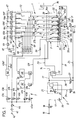
- the main parts of the device 1 are a pot-shaped washing container 2 with a plurality of holders 3 in the interior of the container 2, each for a handpiece 4, in the present exemplary embodiment six holders 3, a water supply system 5, with which water is supplied to the washing container 2 and also led by it can, a compressed air supply system 7, a care agent supply system 8 and an ultrasonic cleaning device, of which only one ultrasonic vibrator 9 is shown to act upon the washing container 2 with ultrasound.
- the rinsing container 2 has an inlet and outlet line 12, which is part of the water supply system 5, and with a water outlet 13.
- the water inlet line 17, which can be connected to a water connection 16 the following are arranged one behind the other in the direction of flow: a first electromagnetic valve 18, a pump 19, in particular for increasing the pressure, a softening device 21 and a condenser 22.
- the softening device 21 is connected directly to the water drain 13 through a discharge line 24, in which one or two solenoid valves 25, 26 are arranged one behind the other, for flushing and Regeneration of the softening device to be able to discharge the waste water directly into the water drain 13.
- a fourth electromagnetic valve 27 is arranged in a line section 28 connecting the water supply line 17 behind the softening device 21 and the discharge line 24 behind the electromagnetic valve 26.
- a second pump 29 and a fifth solenoid valve 31 are arranged one behind the other in the feed and discharge line 12 in the direction of the water drain 13.
- the water supply line 17 is connected between the rinsing tank 2 and the second pump 29 with the supply and discharge line 12, in this area also a further line section 32 leading to a water level display device or measuring device 33 with a level switch 34a, 34b.
- the maximum water level in the rinse tank 2 is designated 35. It is located above the handpieces 4 placed in or on the holders 3. Branches between the second pump 29 and the electromagnetic valve 31 a further branch line 36, which leads to an intermediate store 37, which is arranged above the washing compartment 2.
- An electrical heating device 38 with at least one electrical heating element is arranged in the bottom region of the washing compartment 2.
- a surfactant metering device 51 is arranged in the compressed air line 41e and is connected directly or through a line section to a surfactant storage container 52.
- a fill level meter 53, 54 and an electrical switch 55, 56 are assigned to each of the two storage containers 48, 52.
- the compressed air lines 41d and 41e are brought together to form a common compressed air line 41f, which likewise opens into the rinsing container 2 above the maximum water level 35.
- Each holder 3 is assigned two feed lines, namely a first feed line 57a-57f and a second feed line 58a-58f.
- the feed lines 58a-58f are each connected to the common feed line branch 41a2, in which a check valve 59 opening in the flow direction is arranged.
- the first supply lines 57a-57f are connected to a common care agent supply line 61, which starts from a care agent pressure container 62, for example a spray bottle, wherein an electrically controllable valve 63 is provided, with which the delivery of the care agent into the Supply line 61 is selectively controllable by opening and closing.
- a measuring or monitoring device 64 with an electrical switch 65 is arranged in the supply line 61.
- An electromagnetic valve 66a to 66f is arranged in each of the first supply lines 57a-57f, which are combined in a care agent distributor 67, for example in the form of a valve block.
- the compressed air line 41b branches in a compressed air distributor 68 in the number of holders 3 corresponding number of compressed air line branches 69a-69f, in each of which a throttle and a check valve opening in the flow direction are arranged, and which are each connected to one of the first supply lines 57a-57f.
- the first supply lines 57a-57f are also each connected to the compressed air line branch 41a1 by a line section 71, a throttle and a check valve opening in the flow direction also being arranged in the line section 71.
- the line connections described above are assigned to a compressed air distributor 72.
- a steam line 73 extends from the area above the maximum water level 35 from the washing container 2 to the condenser 22, in which steam flowing from the washing container 2 condenses and is fed back to the water supply system 5.
- the steam line 73 ends in the area of the condenser 22 as a free exhaust air line 74.
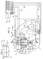
- the plug-in part 76a can consist of two parts which are arranged on both sides of the container wall 2b of the washing container 2, the one part, here the inner part, passing through the container wall 2b in a suitable hole and resting with a shoulder on the inner edge of the hole, while the other, here outer, part from the other side of the container wall 2b is placed like a sleeve on one part and is connected to it, for example detachably by thread or inseparably, for example by welding or soldering.
- the rinsing container 2 is preferably widened in its upper edge region with a horizontal flange wall 2c starting from the container wall 2b, which is followed by an approximately vertical edge wall 2d at the top.
- the lateral widening is dimensioned larger than the plug-in part 76a, so that it can be arranged in the region of the edge widening 83 thus formed and can pass through the flange wall 2c.
- 2e denotes a lid which rests on the edge wall 2e and thus covers the carrier unit 75.
- the upper part of the socket part 76a projects upward in the form of a pin and thus forms one or more pins 79, preferably in the number of feed lines 57a-57c and 41a2 passing through the socket 76, onto which the socket part 76b assigned to the carrier part 75 has one or more Plug-in recess of the appropriate number and corresponding shape and size can be clipped on.
- the pins 79 are preferably formed by sleeves 79a each having a shoulder 79b, which are inserted and fastened in the plug-in part 76a.
- the socket part 76b assigned to the carrier 75 is connected by a preferably Z-shaped shaft 84 to a plurality, here three holders 3, which are arranged in the corners of an imaginary triangle, two holders 3a, 3b near the container wall 2b being symmetrical to one another
- the vertical plane VE extending at right angles to the circumferential wall 78 is arranged and an associated further holder 3c is offset toward the side facing away from the associated plug-in part 76b, the holders 3a, 3b, 3c being arranged on the corner points of the imaginary equilateral triangle.
- the holders 3 are formed by round plug-in pins 85 which, in the case of the upright arrangement of the handpieces 4 in the exemplary embodiment according to FIGS. 1 to 5, are formed by a carrier base part 86a, 86b, 86c assigned to each holder 3 extend upwards and are preferably releasably attached.
- a union nut 87 can be used, which engages over a base flange 88 of the associated plug pin 85 and is screwed onto the associated, preferably round, carrier base part 86.
- Seals must be provided to seal the channel sections between the carrier base part 86a, 86b, 86c and the base flange 88.
- a common seal in the form of a sealing disk 70b arranged between the carrier base part 86a, 86b, 86c and base flange 88 is provided, which has holes for receiving the centering pins and for the channels.
- This configuration makes it possible to arrange and treat different handpieces 4, specifically different handpieces 4 from one manufacturer and / or one or more different manufacturers (third-party manufacturers) on the carrier 75.
- the base flanges 88 which are of the same design in this regard, thus form adapters for the arrangement of different plug pins 85.
- the plug-in / rotary coupling 39 are assigned latching elements which bring about a releasable latching of the handpieces 4 in the plugged-on position, as is usual with handpieces for a quick connection.
- the compressed air line 41a2 is connected to the socket part 76a, and extends through the socket 76 and the shaft 84 to the carrier base parts 86a, 86b, 86c.
- the associated second feed line 58a to 58c branches off in each case and extends as an axially parallel channel through the associated plug-in pin 85, from which it opens out radially into an opening 58g, preferably in a circumferential groove and between two ring seals, as is inherent in plug-in / rotation Couplings is known.
- the first supply lines 57a-57c are also connected to the socket part 76a assigned to the washing compartment 2, and they extend further as separate supply channels 57g in the carrier part 75, wherein they extend coaxially in the region of the associated plug pin 85 and axially offset from the mouth openings 58g Mouth openings 57h emerge from the associated plug-in pin 85, namely coaxially in the case of a plug-in pin 85b for an electromotive handpiece and also radially in a circumferential groove between two sealing rings in the case of a plug-in pin 85a for a so-called turbine handpiece.
- the mouth openings 57g, 58g of the feed channels 57a-57c, 4 fluid channels or the cavities are continued in the associated handpiece, which the mechanical gear train, e.g. a drive spindle.
- a blocking valve 92 is provided in the plug-in part 76a in each first supply duct 57a-57c and in the compressed air line 41a2, the purpose of which is to close the associated duct when no carrier unit 75 is mounted.
- These check valves 92 are each formed by a valve ball 93 in a widened channel section in the plug-in part 76a, which is arranged upstream of a valve seat surrounding a valve opening. If there is no carrier unit 75, the valve balls 93 close the shut-off valves 92 on account of an existing pneumatic closing pressure, wherein the valve balls 93 can be provided with compression springs that press against the associated valve seat.
- the shaft 84 of the carrier unit 75 consists of four thin tubes 95a-95d, preferably made of metal, which form the supply line channels 57a-57c and the compressed air line 41a2 and which extend in a Z-shape between the plug-in part 76b and the three carrier base parts 86 and thus are preferably tightly connected laterally, for example by gluing or soldering.
- the vertical sections of the pipes 95a-95c forming the feed lines 57a-57c extend in a vertical plane VE2 running at right angles to the vertical plane VE near the container wall 2b, and they are bent in each case to the associated carrier base part 86.
- the tube 95d forming the compressed air line 41a2 extends in the vertical plane VE approximately parallel to the central tube 95b to the carrier base part 86c. From here, the compressed air line 41a2 is connected to the carrier base parts 86a, 86b by two V-shaped horizontal pipe pieces 95e. The arrangement of the tubes 95 in several planes results in a stable configuration.
- a preferably angular support part 96 is arranged on the outside, which not only connects the tubes 95a, 95b, 95c and thus stabilizes them, but also ensures lateral support on the inner wall of the washing compartment 2.
- the outer vertical leg of the support part 96 is preferably covered with a continuous or two spaced-apart buffer pieces 96a made of soft material, which ensure a soft support in the peripheral wall 2b.
- a further carrier unit 75a of the same configuration is provided, however, in a position rotated horizontally by 180 °, this carrier unit 75a resting in the position offset to the carrier unit 75 at right angles to the vertical plane VE on the opposite edge flange 2c with the socket part 76b in that socket 76. Because of the twisted arrangement of the carrier units 75, 75a, the six pieces of holders 3 or carrier base parts 86 which are present take the form of a parallelogram.
- the horizontal cross-sectional shape of the washing container 2 is preferably adapted to this shape and is thus parallelogram-shaped, the corners of this parallelogram shape preferably being rounded.
- the first supply lines 57d-57f and a branch line of the compressed air line branch 41a2 extend in a corresponding manner to the carrier unit 75a.
- the flat and vertical container side walls 2b1 to 2b4 delimiting an inner corner each enclose an angle of approximately 60 ° or approximately 120 °.
- the initial region a of the container side walls 2b2, 2b4, which extend obliquely with respect to the carrier unit 75 or lie opposite the vertical plane VE can be arranged parallel to the latter.
- These container side wall parts are each designated 2b5.
- the width a of these container side wall parts 2b2, 2b4 corresponds approximately to the distance that the brackets 3a, 3b have from the container side wall 2b3.
- An advantage of the oblique-angled or parallelogram-shaped cross-sectional shape of the washing container 2 consists in a good use of space or adaptation to the support units 75, 75a, so that as little washing water as possible is consumed and the handpieces 4 used are still flushed around.
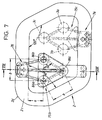
- FIGS. 7 and 8 differs from the one described above only in that instead of a standing arrangement for the handpieces 4, a hanging arrangement is provided, that is, the carrier base parts 86 are located with the plug pins 85 in a position rotated by 180 ° in the upper region of the washing compartment 2, the plug pins 85 pointing downward and the handpieces 4 being attached in a hanging manner from below.
- a horizontal support arm 97 is provided, which extends from the plug-in part 76b most distant support base part 86c to the opposite edge of the washing compartment 2 and rests on the opposite edge flange 2d with a damper part 99 made of soft material and attached to its underside.
- shaft 84 and tubes 95a-95c extend substantially horizontally.
- this carrier unit 75b and also the further appropriately designed, but rotated carrier unit 75c are designed or arranged corresponding to the carrier unit 75 or 75a.
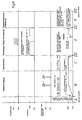
- time and treatment steps A-E are plotted on the abscissa and time steps are plotted on the ordinate.
- Rinsing of the softening device 21 is only activated in treatment step A if the resin of the softening device 21 has been regenerated with brine at the end of the previous care cycle.
- the brine which remains in the resin tank until a new maintenance cycle starts, is rinsed out with fresh water.
- the handpieces 4 to be maintained are assigned to the associated holders 3 by plugging them on.
- the maintenance process is then initiated, which is semi-or also by means of an electrical control device, not shown, which is connected to the associated functional elements by signal and control lines can run fully automatically.
- the solenoid valve 18 with an associated flow limiter
- the washing container 2 is filled with water.
- the level switch 34 emits a signal to switch on the heating device 38.
- the detergent is dosed by opening the solenoid valve 45d for a certain period of time.
- the metered amount of detergent is pressed by compressed air through line 41f into the washing container 2.
- the rinsing water flows through the annular gaps between the plug pins 85 and the instruments or handpieces 4 in their interior spaces (media channels, cavities for the tool drive) if no sealing rings are arranged on the plug pins in front of and behind the orifices 57g, 58g, and that Air in the handpieces 4 is able to flow out at openings, in particular at the front ends of the handpieces 4, when the arrangement is standing or vice versa when the handpieces 4 are arranged in a hanging manner (FIGS. 4 and 8).
- bypass channels 57i, 58i are to be provided, which open out the feed channels 57, 58 in the region, in particular the foot region, of the plug pins 85 radially outward, specifically outside the associated pair of sealing rings.
- the compressed air heater 46 can be optionally switched on or controlled for this purpose.
- the compressed air draining the cavities is at the same time a "sealing air" that prevents the water from entering the cavities.
- the throttles in the compressed air distributors 72 and 68 also serve to distribute the compressed air evenly over all supply lines 57a-57f. A few seconds after the solenoid valve 45a is opened, the ultrasonic vibrator 9 is excited for a short time for ultrasonic cleaning. Then this compressed air supply is switched off. The same process is repeated at about 65 ° C.
- the above-described pressurized air supply to the cavities accommodating the mechanical drive elements is of essential importance. It leads to a drainage of the cavities, so that none in the subsequent ultrasonic cleaning Cavitation damage occurs on the cavity walls and the surfaces of the drive elements.
- the water is then further heated until it boils or reaches a temperature that is necessary for disinfection. During this disinfection in treatment step C, the handpieces are wetted inside and outside with boiling water and thus disinfected. This disinfection process takes a predetermined time. The water is then pumped into the intermediate store 37 for later reuse in the case of a subsequent cleaning by means of the pump 29.
- the handpieces 4 are blown out by opening the solenoid valve 45b with compressed air heated by the air heater 46, this hot compressed air through the compressed air line branches 41a1 and 41a2 both through the supply lines 57a-57f and is also supplied to the feed lines 58a-58f at the same time.
- the care is then carried out by opening the valves 63 and 66a-66f, as a result of which the care agent, here a care spray, is sprayed under pressure through the feed lines 57a-57f into the cavities in the handpieces 4 which hold the mechanical drive elements.
- the water is pumped into the drain 13 by means of the pump 29.
- the solenoid valves 66a-66f ensure a fairly precise dosage of the care product, even in the event that not all holders 3 are filled with handpieces 4. By keeping the solenoid valves 66, which are assigned to unoccupied holders 3, closed, it is prevented that care products get into the feed lines 57a-57f and are then blown into the associated handpiece with excessive volume the next time the associated holder 3 is occupied. This would not only imply an avoidable loss of care products, it would also increasingly burden the fleet with care products.
- the solenoid valves 66 can be controlled manually or automatically.
- the rinsing container 2 can preferably have a sensor 101 on the outside of the edge wall d2, e.g. a magnetic switch 101 can be assigned, which determines the presence or absence of the carrier unit 75 and emits a signal which only causes the associated valve or valves 66 to open when the carrier unit 75 is present.
- a switching magnet 102 for actuating the magnetic switch is provided on the outside of the plug connection part 76b.
Landscapes
- Health & Medical Sciences (AREA)
- Epidemiology (AREA)
- Life Sciences & Earth Sciences (AREA)
- Animal Behavior & Ethology (AREA)
- General Health & Medical Sciences (AREA)
- Public Health (AREA)
- Veterinary Medicine (AREA)
- Oral & Maxillofacial Surgery (AREA)
- Dentistry (AREA)
- Dental Tools And Instruments Or Auxiliary Dental Instruments (AREA)
- Detergent Compositions (AREA)
- Apparatus For Disinfection Or Sterilisation (AREA)
Applications Claiming Priority (2)
| Application Number | Priority Date | Filing Date | Title |
|---|---|---|---|
| DE4235712 | 1992-10-22 | ||
| DE4235712A DE4235712C2 (de) | 1992-10-22 | 1992-10-22 | Verfahren zum Reinigen und/oder Desinfizieren und/oder Pflegen von ärztlichen oder zahnärztlichen Instrumenten und Vorrichtung zur Durchführung des Verfahrens |
Publications (3)
| Publication Number | Publication Date |
|---|---|
| EP0594202A2 true EP0594202A2 (fr) | 1994-04-27 |
| EP0594202A3 EP0594202A3 (fr) | 1994-08-03 |
| EP0594202B1 EP0594202B1 (fr) | 1998-01-14 |
Family
ID=6471116
Family Applications (1)
| Application Number | Title | Priority Date | Filing Date |
|---|---|---|---|
| EP93117165A Expired - Lifetime EP0594202B1 (fr) | 1992-10-22 | 1993-10-22 | Procédé pour le nettoyage et/ou la désinfection et/ou le traitement d'instruments médicaux ou dentaires dispositif pour réaliser ce procédé |
Country Status (4)
| Country | Link |
|---|---|
| EP (1) | EP0594202B1 (fr) |
| JP (1) | JP2732790B2 (fr) |
| AT (1) | ATE162064T1 (fr) |
| DE (2) | DE4235712C2 (fr) |
Cited By (5)
| Publication number | Priority date | Publication date | Assignee | Title |
|---|---|---|---|---|
| DE9417660U1 (de) * | 1994-11-04 | 1995-01-26 | Hupfer Metallwerke Gmbh & Co, 48653 Coesfeld | Instrumententräger |
| DE4342573A1 (de) * | 1993-12-14 | 1995-06-22 | Miele & Cie | Verfahren zum Reinigen, Spülen und thermischen Desinfizieren von Labor- und Operationsinstrumenten, insbesondere von MIC-Instrumentarium |
| WO1996033819A1 (fr) * | 1995-04-24 | 1996-10-31 | Lawrence Ralph Dawson | Procede et appareil de nettoyage d'elements creux |
| EP2138127A1 (fr) | 2008-06-27 | 2009-12-30 | Oro Clean Chemie AG | Appareil de nettoyage |
| CN104148339A (zh) * | 2014-07-31 | 2014-11-19 | 咸阳西北医疗器械(集团)有限公司 | 牙科手机注油清洗系统及其注油清洗方法 |
Families Citing this family (3)
| Publication number | Priority date | Publication date | Assignee | Title |
|---|---|---|---|---|
| DE19502133A1 (de) * | 1995-01-25 | 1996-08-01 | Tiller Hans Juergen | Verfahren zur Sterilisation von metallischen medizinischen Instrumenten |
| JP2005270212A (ja) * | 2004-03-23 | 2005-10-06 | J Morita Tokyo Mfg Corp | 歯科用治療椅子 |
| JP4636304B2 (ja) * | 2004-03-23 | 2011-02-23 | 株式会社モリタ東京製作所 | 歯科用治療椅子 |
Family Cites Families (7)
| Publication number | Priority date | Publication date | Assignee | Title |
|---|---|---|---|---|
| US3873071A (en) * | 1973-08-01 | 1975-03-25 | Tatebe Seishudo Kk | Ultrasonic wave cleaning apparatus |
| DE3104237C2 (de) * | 1981-02-06 | 1991-04-18 | Kaltenbach & Voigt Gmbh & Co, 7950 Biberach | Vorrichtung zur Abgabe von Pflegemittel an ärztliche, insbesondere zahnärztliche Handstücke |
| JPS58108817U (ja) * | 1982-01-20 | 1983-07-25 | 塚田 洋四郎 | 洗滌装置 |
| DE3239549A1 (de) * | 1982-10-26 | 1984-04-26 | Dental-Festin GmbH & Co KG, 2730 Zeven | Geraet zur reinigung von instrumenten der zahnmedizin |
| DE3324939A1 (de) * | 1983-07-11 | 1985-01-24 | Siemens AG, 1000 Berlin und 8000 München | Verfahren und vorrichtung zur reinigung und desinfektion von aerztlichen, insbesondere zahnaerztlichen, instrumenten |
| DE4024171C2 (de) * | 1990-07-30 | 1996-02-22 | Kaltenbach & Voigt | Verfahren und Pflegesatz zum Desinfizieren und Pflegen von ärztlichen, insbesondere zahnärztlichen Instrumenten |
| DE4125223C2 (de) * | 1990-07-30 | 1995-10-19 | Kaltenbach & Voigt | Pflegeeinrichtung zur Pflege ärztlicher und/oder zahnärztlicher Instrumente in einem Spülbehälter |
-
1992
- 1992-10-22 DE DE4235712A patent/DE4235712C2/de not_active Expired - Fee Related
-
1993
- 1993-10-22 DE DE59307988T patent/DE59307988D1/de not_active Expired - Fee Related
- 1993-10-22 JP JP5265274A patent/JP2732790B2/ja not_active Expired - Fee Related
- 1993-10-22 EP EP93117165A patent/EP0594202B1/fr not_active Expired - Lifetime
- 1993-10-22 AT AT93117165T patent/ATE162064T1/de not_active IP Right Cessation
Cited By (9)
| Publication number | Priority date | Publication date | Assignee | Title |
|---|---|---|---|---|
| DE4342573A1 (de) * | 1993-12-14 | 1995-06-22 | Miele & Cie | Verfahren zum Reinigen, Spülen und thermischen Desinfizieren von Labor- und Operationsinstrumenten, insbesondere von MIC-Instrumentarium |
| DE4342573C2 (de) * | 1993-12-14 | 2002-09-12 | Miele & Cie | Verfahren zum Reinigen, Spülen und thermischen Desinfizieren von Labor- und Operationsinstrumenten, insbesondere von MIC-Instrumentarium |
| DE9417660U1 (de) * | 1994-11-04 | 1995-01-26 | Hupfer Metallwerke Gmbh & Co, 48653 Coesfeld | Instrumententräger |
| WO1996033819A1 (fr) * | 1995-04-24 | 1996-10-31 | Lawrence Ralph Dawson | Procede et appareil de nettoyage d'elements creux |
| GB2318166A (en) * | 1995-04-24 | 1998-04-15 | Lawrence Ralph Dawson | Method and apparatus for cleaning hollow elements |
| GB2318166B (en) * | 1995-04-24 | 1998-09-09 | Lawrence Ralph Dawson | Method and apparatus for cleaning hollow elements |
| US5985038A (en) * | 1995-04-24 | 1999-11-16 | Dawson; Lawrence Ralph | Method and apparatus for cleaning hollow elements |
| EP2138127A1 (fr) | 2008-06-27 | 2009-12-30 | Oro Clean Chemie AG | Appareil de nettoyage |
| CN104148339A (zh) * | 2014-07-31 | 2014-11-19 | 咸阳西北医疗器械(集团)有限公司 | 牙科手机注油清洗系统及其注油清洗方法 |
Also Published As
| Publication number | Publication date |
|---|---|
| EP0594202A3 (fr) | 1994-08-03 |
| DE4235712C2 (de) | 1995-08-17 |
| ATE162064T1 (de) | 1998-01-15 |
| DE4235712A1 (de) | 1994-04-28 |
| JPH06205796A (ja) | 1994-07-26 |
| EP0594202B1 (fr) | 1998-01-14 |
| DE59307988D1 (de) | 1998-02-19 |
| JP2732790B2 (ja) | 1998-03-30 |
Similar Documents
| Publication | Publication Date | Title |
|---|---|---|
| EP2408485B1 (fr) | Dispositif de stérilisation d'instruments dentaires | |
| EP0638297B1 (fr) | Procédé et dispositif pour le traitement hygiénique d'instruments médicaux, notamment dentaires | |
| DE60108220T2 (de) | Flüssigkeitsverbindungsvorrichtung für endoskop mit kontrollierbarer fluidleckage | |
| DE4024171A1 (de) | Verfahren zur pflege von insbesondere aerztlichen und zahnaerztlichen instrumenten und pflegeplatz zur durchfuehrung dieses verfahrens | |
| DE102013000064A1 (de) | Verfahren zur Reinigung und / oder Desinfektion von medizinischen/zahnmedizinischen Instrumenten und zahnärztlichen Abdrücken. Wesentliche Bauteile die bei der Anwendung dieses Verfahrens eingesetzt werden können: Verteilerblock zur Verteilung der Medien und Grundkörper mit Düsen. Verfahren zur Herstellung von Düsen und/oder deren Zuleitung | |
| EP0937441B1 (fr) | Dispositif pour le nettoyage intensif d'articles médicaux notamment dentaires | |
| EP2536440B1 (fr) | Appareil de désinfection, de stérilisation et/ou d'entretien d'instruments médicaux, notamment dentaires | |
| EP0594203B1 (fr) | Dispositif pour le nettoyage et/ou la désinfection et/ou le traitement d'instruments médicaux ou dentaires | |
| EP0594202B1 (fr) | Procédé pour le nettoyage et/ou la désinfection et/ou le traitement d'instruments médicaux ou dentaires dispositif pour réaliser ce procédé | |
| DE3108574A1 (de) | Anordnung zum desinfizieren von flexiblen endoskopen mittels einer im kreislauf stroemenden desinfektionsfluessigkeit | |
| EP0865299B1 (fr) | Appareil de nettoyage et/ou de sterilisation d'instruments chirurgicaux | |
| EP0916316B1 (fr) | Dispositif pour le nettoyage et le traitement des instruments médicaux et dentaires | |
| DE4244753C2 (de) | Vorrichtung zum Reinigen und/oder Desinfizieren und/oder Pflegen von ärztlichen oder zahnärztlichen Bearbeitungsinstrumenten, insbesondere Handstücken | |
| DE3334999C2 (de) | Vorrichtung für die Schlußdesinfektion von Endoskopen | |
| DE10156924C2 (de) | Reinigungsmaschine, insbesondere für medizinische Geräte | |
| DE4235699C2 (de) | Vorrichtung zum Reinigen und/oder Desinfizieren und Pflegen von ärztlichen oder zahnärztlichen Handstücken | |
| CH689688A5 (de) | Verfahren zum Reinigen und/oder Desinfizieren und/oder Pflegen von ärztlichen oder zahnärztlichen Instrumenten und Vorrichtung zur Durchführung des Verfahrens. | |
| DE4244752C2 (de) | Vorrichtung zum Reinigen und/oder Desinfizieren und/oder Pflegen von ärztlichen oder zahnärztlichen Bearbeitungsinstrumenten, insbesodnere Handstücken | |
| DE69005915T2 (de) | Desinfektionssystem, insbesondere für zahnärztliche Handstücke. | |
| DE3941103C2 (fr) | ||
| DE2534757C3 (de) | Einrichtung zur elektrischen Behandlung von Flüssigkeiten, die Mikroorganismen enthalten | |
| DE4445434C2 (de) | Spülvorrichtung zum Reinigen von Gegenständen, insbesondere von Endoskopen | |
| DE102014102064A1 (de) | Druckluftunterstützte Reinigung | |
| EP2536442B1 (fr) | Réceptacle pour instruments médicaux, notamment dentaires, et système d'entretien associé | |
| DE4219244A1 (de) | Reinigungs- und Desinfektionsgerät, insbesondere für Endoskope und Verfahren zu dessen Betrieb unter Verbesserung der Desinfektionseigenschaften |
Legal Events
| Date | Code | Title | Description |
|---|---|---|---|
| PUAI | Public reference made under article 153(3) epc to a published international application that has entered the european phase |
Free format text: ORIGINAL CODE: 0009012 |
|
| AK | Designated contracting states |
Kind code of ref document: A2 Designated state(s): AT CH DE FR IT LI SE |
|
| PUAL | Search report despatched |
Free format text: ORIGINAL CODE: 0009013 |
|
| AK | Designated contracting states |
Kind code of ref document: A3 Designated state(s): AT CH DE FR IT LI SE |
|
| 17P | Request for examination filed |
Effective date: 19940825 |
|
| GRAG | Despatch of communication of intention to grant |
Free format text: ORIGINAL CODE: EPIDOS AGRA |
|
| 17Q | First examination report despatched |
Effective date: 19970115 |
|
| GRAH | Despatch of communication of intention to grant a patent |
Free format text: ORIGINAL CODE: EPIDOS IGRA |
|
| GRAH | Despatch of communication of intention to grant a patent |
Free format text: ORIGINAL CODE: EPIDOS IGRA |
|
| GRAA | (expected) grant |
Free format text: ORIGINAL CODE: 0009210 |
|
| AK | Designated contracting states |
Kind code of ref document: B1 Designated state(s): AT CH DE FR IT LI SE |
|
| REF | Corresponds to: |
Ref document number: 162064 Country of ref document: AT Date of ref document: 19980115 Kind code of ref document: T |
|
| REG | Reference to a national code |
Ref country code: CH Ref legal event code: NV Representative=s name: A. BRAUN, BRAUN, HERITIER, ESCHMANN AG PATENTANWAE Ref country code: CH Ref legal event code: EP |
|
| ET | Fr: translation filed | ||
| REF | Corresponds to: |
Ref document number: 59307988 Country of ref document: DE Date of ref document: 19980219 |
|
| ITF | It: translation for a ep patent filed | ||
| PLBE | No opposition filed within time limit |
Free format text: ORIGINAL CODE: 0009261 |
|
| STAA | Information on the status of an ep patent application or granted ep patent |
Free format text: STATUS: NO OPPOSITION FILED WITHIN TIME LIMIT |
|
| 26N | No opposition filed | ||
| PGFP | Annual fee paid to national office [announced via postgrant information from national office to epo] |
Ref country code: FR Payment date: 20041019 Year of fee payment: 12 |
|
| PGFP | Annual fee paid to national office [announced via postgrant information from national office to epo] |
Ref country code: AT Payment date: 20041022 Year of fee payment: 12 |
|
| PGFP | Annual fee paid to national office [announced via postgrant information from national office to epo] |
Ref country code: CH Payment date: 20041025 Year of fee payment: 12 |
|
| PGFP | Annual fee paid to national office [announced via postgrant information from national office to epo] |
Ref country code: DE Payment date: 20041229 Year of fee payment: 12 |
|
| PG25 | Lapsed in a contracting state [announced via postgrant information from national office to epo] |
Ref country code: IT Free format text: LAPSE BECAUSE OF NON-PAYMENT OF DUE FEES;WARNING: LAPSES OF ITALIAN PATENTS WITH EFFECTIVE DATE BEFORE 2007 MAY HAVE OCCURRED AT ANY TIME BEFORE 2007. THE CORRECT EFFECTIVE DATE MAY BE DIFFERENT FROM THE ONE RECORDED. Effective date: 20051022 Ref country code: AT Free format text: LAPSE BECAUSE OF NON-PAYMENT OF DUE FEES Effective date: 20051022 |
|
| PGFP | Annual fee paid to national office [announced via postgrant information from national office to epo] |
Ref country code: SE Payment date: 20051024 Year of fee payment: 13 |
|
| PG25 | Lapsed in a contracting state [announced via postgrant information from national office to epo] |
Ref country code: LI Free format text: LAPSE BECAUSE OF NON-PAYMENT OF DUE FEES Effective date: 20051031 Ref country code: CH Free format text: LAPSE BECAUSE OF NON-PAYMENT OF DUE FEES Effective date: 20051031 |
|
| PG25 | Lapsed in a contracting state [announced via postgrant information from national office to epo] |
Ref country code: DE Free format text: LAPSE BECAUSE OF NON-PAYMENT OF DUE FEES Effective date: 20060503 |
|
| REG | Reference to a national code |
Ref country code: CH Ref legal event code: PL |
|
| PG25 | Lapsed in a contracting state [announced via postgrant information from national office to epo] |
Ref country code: FR Free format text: LAPSE BECAUSE OF NON-PAYMENT OF DUE FEES Effective date: 20060630 |
|
| REG | Reference to a national code |
Ref country code: FR Ref legal event code: ST Effective date: 20060630 |
|
| PG25 | Lapsed in a contracting state [announced via postgrant information from national office to epo] |
Ref country code: SE Free format text: LAPSE BECAUSE OF NON-PAYMENT OF DUE FEES Effective date: 20061023 |
|
| EUG | Se: european patent has lapsed |