EP0594467A1 - Cuisinière à combustion étanche - Google Patents
Cuisinière à combustion étanche Download PDFInfo
- Publication number
- EP0594467A1 EP0594467A1 EP93308488A EP93308488A EP0594467A1 EP 0594467 A1 EP0594467 A1 EP 0594467A1 EP 93308488 A EP93308488 A EP 93308488A EP 93308488 A EP93308488 A EP 93308488A EP 0594467 A1 EP0594467 A1 EP 0594467A1
- Authority
- EP
- European Patent Office
- Prior art keywords
- burner
- exhaust
- oven
- combustion air
- heat transfer
- Prior art date
- Legal status (The legal status is an assumption and is not a legal conclusion. Google has not performed a legal analysis and makes no representation as to the accuracy of the status listed.)
- Withdrawn
Links
Images





Classifications
-
- F—MECHANICAL ENGINEERING; LIGHTING; HEATING; WEAPONS; BLASTING
- F24—HEATING; RANGES; VENTILATING
- F24C—DOMESTIC STOVES OR RANGES ; DETAILS OF DOMESTIC STOVES OR RANGES, OF GENERAL APPLICATION
- F24C3/00—Stoves or ranges for gaseous fuels
- F24C3/04—Stoves or ranges for gaseous fuels with heat produced wholly or partly by a radiant body, e.g. by a perforated plate
- F24C3/06—Stoves or ranges for gaseous fuels with heat produced wholly or partly by a radiant body, e.g. by a perforated plate without any visible flame
- F24C3/067—Ranges
Definitions
- This invention relates to a sealed combustion gas range in which the air required for combustion is drawn from outdoors and all combustion products are vented outdoors and in which there is no air interchange between the range and the structure in which it is located.
- gas ranges in which the burners are located beneath a glass ceramic top, for ease of cleaning and for appearance.
- ranges of this design do not provide for sealed combustion as the air required for combustion is drawn from indoors and the combustion products are vented to the indoors as well.
- gas ranges in which combustion products are exhausted through holes in the aeration bowl of the top burners via an exhaust manifold. In these devices, it is intended that the bottom of the cooking vessel being used will provide a sealing of the burners for capture of the combustion products. However, with these devices the capture of the combustion products is not complete, as there can be significant leakage of combustion products around the vessel. In addition, the air for combustion is drawn from inside the house.
- hob assembly means an assembly which includes a surface for supporting a cooking vessel and which includes burners for heating or cooking primarily by radiation and conduction
- "oven” means an assembly which includes burners in a closed chamber for heating or cooking primarily by radiation and convection within the chamber
- range means a combination of a hob assembly and an oven.
- a hob assembly for sealed combustion comprising:
- the first surface is provided by a burner insert, which defines a generally radial passageway.
- the insert is supported in a burner box, which is spaced from the solid heat transfer surface by a layer of insulating material, the insulating material then serving to define the width or height of the passageway with the first surface parallel to the heat transfer surface.
- the insulating material can further provide a seal between the burner insert and the heat transfer surface.
- the passageway prefferably has a height or width of 2-3 mm, and length in the radial direction that is of the order of 10 times greater than the height.
- the circumferential extent or breadth of the passageway will vary with radius, but preferably is an order of magnitude greater than the radial extent of the passageway.
- a hob assembly as described above in combination with an oven to form a range, the oven including at least one burner located therein, wherein the means for supplying a gaseous fuel is connected to each burner of the oven, and wherein the combustion air inlet and the exhaust means are in communication with the oven for, respectively, supplying combustion air thereto and exhausting combustion products therefrom.
- FIG. 1 shows a hob assembly 70 for installation on a standard gas range 1 or incorporation into a range according to the present invention.
- hob burners 3 which are preferably uniburner assemblies, but could also be any type of burners commonly used in advanced technology market ranges, such as sealed or unsealed blue flame or infrared ceramic burners. These type of burners are known in the art, and are typically constructed of brass, iron, steel, aluminum, or ceramic or combinations thereof.
- the hob burners 3 preferably have nickel plated steel burner caps, for increased burner life.
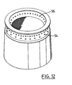
- the burners are provided with burner caps 92, each having an outer array of ports 94 in an outer conical face, which are inclined upwards at a small angle.
- the outer array of ports 94 preferably includes ports of different diameters.
- ports having diameters of 1.4 mm and 1.9 mm are arranged as shown.
- the burners 3 are provided with a venturi arrangement at the inlet for each burner. Flow of combustion gas then draws the required combustion air into the burner, which discharges through the combustion ports.
- the hob burners 3 are supported by a support rack 17, which is integral to an air box 2, and also by gas valve orifice hoods 16.
- the air box 2 also defines a chamber for the flow of incoming combustion air, as will be described below.
- the embodiment of the present invention shown in Figure 1 has four hob burners 3, two of the hob burners 3 located on burner assembly 3A and the other two hob burners 3 located on burner assembly 3B. As such there are two ceramic burner boxes 4 and four ceramic inserts 5 that slip fit into the burner boxes 4 to form combustion chambers for the hob burners 3.
- the hob assembly 70 may comprise any number of hob burners.
- the burner boxes 4 are generally rectangular in shape and include apertures located therein for placement of the ceramic inserts 5.
- the ceramic inserts 5 are generally annular in shape, and have a central opening for the burner 3.
- the inserts 5 include a plurality of holes 82 located proximate the outer edge of the insert 5, providing an exhaust vent.
- the inner edge of the insert 5 is preferably chamfered, as shown in Figure 6 at reference numeral 84, or countersunk.
- the burner boxes 4 and inserts 5 are preferably made from vacuum formed alumina silicate fibres rated at 1260°C, which have been machined and then impregnated with colloidal silica for rigidity.
- each burner box 4 At each bottom corner of each burner box 4 is a push fit thimble 7 sealed thereto by a high temperature silicone sealant. Affixed in each thimble 7 is a compression spring 6, which ensures that the burner box 4 is pressed against a ceramic fibre paper gasket (described below), which separates the burner box 4 from the ceramic cooking surface 26.
- Springs 6 are sufficiently compressible to allow the cooking surface 26 to flex should it be subjected to mechanical shocks. Also, springs 6 should not exert substantial upward pressure on surface 26, as such pressure will tend to warp the surface 26, but should exert sufficient pressure to maintain a good seal between the burner boxes 4, ceramic fibre gasket and cooking surface 26.
- the burner boxes 4 are fitted directly into a hob chassis 8 as drop-in units.
- the hob chassis 8 is fastened to the top of the range 1 with an appropriate amount of bolts 9 and nuts (not shown).
- An exhaust port 11 is located between the two burner boxes 4, and provides for the separation of the burner boxes 4 necessary for proper use of the hob assembly.
- the exhaust port 11 is generally box-like and is integral with hob chassis 8. As will be described below, the exhaust port 11 is connected to a central exhaust system which exhausts the combustion products to the outdoors.
- the gaseous fuel for combustion in the hob burners 3 is supplied from an external source (not shown) to a gas manifold 19 in known manner.
- Agas pressure regulator 18 is used to control and maintain a uniform pressure in gas manifold 19.
- a common gas manifold 19 supplies gas to all four hob burners 3, the gas flow commencing when a solenoid gas valve 20 is energized, the solenoid valve 20 providing on electrically actuated safety valve.
- the gas manifold 19 could also be partitioned such that two or four solenoid gas valves are used to supply the hob burners 3. Such a partitioning has several advantages, as will be outlined below.
- hob burner gas valves 21 are installed on the gas manifold 19 at the front of the range 1.
- the hob burner gas valves 21 extend through a control knob panel 38 and burner control knobs 22 are attached to the portions so extending.
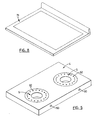
- the top of the hob assembly 70 comprises a glass ceramic cooking surface 26.
- the cooking surface 26 used herein is made of CERAN (trade mark) glass ceramic, manufactured by schott, Germany,and has a length of 752 mm, a width of 573 mm and a thickness of 4 mm. Glass ceramic as identified above has a high physical strength, a low thermal expansion and good heat transfer characteristics.
- cooking surface 26 may be steel, stainless steel or aluminum or may comprise discs of glass ceramic, steel, stainless steel or aluminum imbedded in another material.
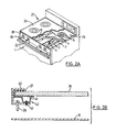
- a metal bezel 27 Prior to being installed in a metal bezel 27, which is preferably aluminum or stainless steel, the circumference of cooking surface 26 is surrounded by a foam rubber strip 40. As is shown in Figure 2B, cooking surface 26 is secured in bezel 27 by a set of metal strips 41, which surround the bottom of the surface 26 proximate the foam rubber strip 40, Compression clips 42 and screws 43. By turning screws 43 such that clips 42 abut strips 41, the bezel 27 can be firmly attached to cooking surface 26.
- a closed cell foam rubber gasket 31 is attached to the bottom of bezel 27. Gasket 31 forms a seal with metal strips 32, 33, which are attached to chassis 8. The seal so formed prevents room air from entering hob assembly 70.
- the cooking surface 26 is positioned on the hob chassis 8 by the use of two locating pins 28, which extend downwardly from bezel 27, each locating pin 28 being adapted to engage a hole located in hob chassis 8.
- bezel 27, and hence cooking surface 26, is not mechanically fastened to hob chassis 8, and therefore can be easily removed by lifting, for example if cleaning is desired.
- FIG. 8 An alternate bezel arrangement is shown in Figure 8.
- the cooking surface fits into a metal frame 71, preferably of steel or stainless steel, and is sealed thereto by silicone sealant or any other suitable adhesive.
- a ceramic fibre paper gasket 29 separates the burner boxes 4 and the cooking surface 26.
- two gaskets 29 are provided, one for each side of the hob assembly 70.
- a single gasket 29 may be used, underlying the whole of the cooking surface 26.
- the preferred gasket 29 is sold under the trade mark Fl-BERFRAX 970, such gaskets having a composition of approximately 52% A1 2 0 3 and 48% Si0 2 and having a nominal uncompressed thickness of 3.20 mm.
- Apertures are provided in the gasket 29 proximate the location of the burners 3, such that the products of combustion of the gaseous fuel can directly contact the bottom of the cooking surface 26.
- the apertures are smaller than the ceramic inserts 5, such that the gasket 29 seals any gap between the burner box 4 and the ceramic insert 5, as is shown in Figure 7.
- the cooking surface 26 thus defines a narrow annular heat transfer passageway 86 above each insert 5, the width or height of the passageway being equal to the thickness of the ceramic fibre gasket 29, which in the compressed state is in the range of 2-3 mm. This creates a narrowgap, through which the hot combustion products must pass. This promotes heat transfer as first, the combustion products must travel at a relatively high velocity, and secondly, unlike some earlier proposals, the combustion products pass close to the cooking surface 26.
- the top of the inserts 5 can be shaped to give any desired velocity profile in the passageway 86.
- the passageway can decrease in width or height in the radially outwards direction, so as to maintain a constant velocity.
- each insert 5 has an approximate diameter of 178 mm with the aperture in the gasket 29 being 165 mm.
- the outer diameter of the chamfered section 84 is 102 mm, with the holes 82 on a circle of diameter of 146 mm, to give a radial path length through the passageway 86 of 22 mm.
- the ratio of radial path length to width of the passageway 86 is then in the range of approximately 11 to 1.
- the circumferential extent or breadth of the passageway 86 increases from 320 mm at the inlet side to 460 mm at the holes 82.
- the combustion products then enter a chamber 88, which is formed by the facing surfaces of the burner box 4 and the insert 5. From the chamber 88, the combustion products are exhausted through a passage 90, located in burner box 4, and into the exhaust port 11.
- the passages 90 which are most clearly shown in Figure 5, are sized to control the flow rate of the combustion products from each burner 3.
- burner exhaust orifice hoods 15 are fitted into passages 90, for exhausting the combustion products from the individual hob burners into the exhaust port 11.
- exhaust port 11 is covered with a ceramic paper gasket 12 and then a cover plate 13, preferably made of steel, which is fixed to the exhaust port 11 by a sufficient quantity of machine screws 14.
- the exhaust port 11 is insulated from the heat produced by the combustion of the gaseous fuel by a ceramic insulation blanket 30 placed above plate 13.
- the ceramic insulation blanket 30 also provides a surface level with the ceramic paper gasket 29.
- the ceramic inserts 5 attain temperatures in excess of 600°C and glow bright red, thereby transmitting radiant energy to the cooking surface 26 and any cooking utensil located thereon.
- the radiant energy is concentrated over the annular- shaped ceramic insert 5 and above the burner 3, resulting in even heat distribution.
- the ports 96 on the inside of the burner 3 produce the effect of a second burner with the heat directed towards the centre of the cooking zone. This results in a more uniform heat distribution across the cooking zone, and better thermal response and increased thermal efficiency, as compared to just outer ports 94, and enables higher burner inputs to be used. Also, the more uniform heat distribution reduces the possibility of breakage of the cooking surface 26 due to thermal stress.
- the surface 26 is protected by a cooking surface thermal protection system.
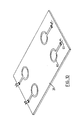
- the glass ceramic cooking surface 26 has attached to it pairs of precious metal strips 60 as shown in Figure 10.
- the precious metal strips of each pair are concentric and define an annulus therebetween.
- the pairs of precious metal strips 60 are attached to the underside of the cooking surface 26 proximate to the location of the hob burners 3.
- the strips 60 are attached to cooking surface 26 by screen printing a thin film conductor gold resinate paste containing 15% gold and a small amount of non-precious metals in the form of soluble organometallic compounds.
- the silver termination is also attached by screen printing, using a silver conductor paste containing 82.2% silver and a small amount of soluble non-precious organometallic compounds.
- the pastes are then dried at between 80°C and 100°C for approximately 20 minutes, and then fired for approximately 2 hours to a peak temperature of 750°C with a 10 minute soak time.
- the gold portion of strips 60 is 0.1 to 0.3 microns in thickness and the silver termination portion is 10 to 14 microns in thickness.
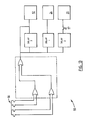
- the precious metal strips 60 are connected by high temperature insulated electrical wire 61 to a resistance measuring circuit, of which a functional block diagram is shown in Figure 9.
- the resistance measuring circuit measures the resistance of the cooking surface in the annulus between the metal strips in each pair. As stated by the manufacturer of the glass ceramic used herein, the resistance varies with the temperature of the glass ceramic cooking surface 26.
- the resistance of the annulus between strips 60 is connected in series with a resistance of known value and a voltage applied across this combination. The voltage at the lunction is then rectified, filtered and compared with voltages for known temperatures. Should the temperature of the surface 26 as determined by this circuit rise above a predetermined value, the circuit automatically disables the solenoid gas valve 20, shutting off the gas supply to the hob burners 3. Once the temperature of the cooking surface 26 has dropped below the cut-off level, the solenoid gas valve 20 is re-energized to allow burner operation to resume.
- the resistance measuring circuit can be adapted to shut off gas flow to only the burner underneath the area where the temperature of the cooking surface 26 has increased beyond the threshold temperature, thus allowing the other burners to remain in normal operation.
- an oven adapted for sealed combustion.
- the corners of the oven box 44 are sealed to prevent any loss of air for combustion to the insulated oven walls.
- the corners of the oven box 44 are sealed using angled metal strips 63, which are secured to the oven box 44 by sheet metal screws (now shown).
- a ceramic fibre paper gasket (not shown) is placed between the oven box 44 and the angled metal strips 63.
- the bottom of the oven box 44 is fitted with combustion air opening 45 to improve the air distribution along the length of oven bake burner 46.
- combustion air for the oven bake burner46 and the oven broil burner 62 is supplied from a two compartment air intake/exhaust manifold 49 through an air duct 50 located at the rear of range 1.
- the combustion air then enters an air chamber 51 located beneath the oven box 44 and is distributed via the combustion air openings 45.
- the oven exhaust is connected directly to exhaust port 11 by means of a flanged plate 47 with an appropriately sized orifice 48 located thereon, as shown in Figure 3A.
- the orifice 48 regulates the flow of combustion products from the oven into the exhaust port 11, and is sized with the passages 90, to give balanced exhaust flow.
- the gaseous fuel for combustion is supplied to the oven from an external source (not shown) through a dual thermal bi-metal gas control valve 64, which utilizes a standard gas manifold arrangement.
- Figure 4A shows a range according to the present invention which includes both a hob assembly and an oven.
- this embodiment comprises a centralized air intake/exhaust system.
- a concentric vent system 53 is used to vent the combustion products to outdoors and to draw fresh combustion air inside from outdoors.
- the vent system 53 is fabricated from thin wall stainless steel tubing inside a type B steel vent with a twist lock connection.
- the vent system 53 terminates outdoors in a vent terminal 54.
- the combustion products flow outward through the inner pipe of the vent system 53 while fresh combustion air flows inward through the outer pipe resulting in heat exchange between the two flows which improves the efficiency of the range, while maintaining the exterior of the vent system 53 at a reasonable temperature. Also, in this arrangement the combustion products are completely separated from the fresh combustion air.
- the vent system 53 is attached to an air intake/exhaust manifold 49 located on the back of the range 1.
- the manifold 49 consists of two separate compartments coupled together to form a single unit, as is illustrated in Figure 4C. Air openings 49A and 49B in the manifold 49 distribute combustion air from the vent system 53 to air box 2 and air duct 50 respectively.
- Combustion air is supplied to the hob assembly 70 as follows. Combustion airflows from vent system 53 into air intake/exhaust manifold 49, through air opening 49A and into air box 2. The combustion air then flows upwardly through the annulus between the burners 3 and the ceramic insert 5, and is used in the combustion of the gaseous fuel. The combustion products are drawn in into exhaust port 11 and then into the intake of an exhaust blower 52. The outlet of exhaust blower 52 is connected to the exhaust portion of the air intake/exhaust manifold 49 and is then exhausted into the inner pipe of the vent system 53.
- Exhaust blower 52 is used to vent the combustion products outdoors.
- the blower 52 operates at a constant speed and maintains a negative pressure throughout the range.
- the blower 52 is selected to provide a capacity in excess of the maximum amount of combustion products generated. Such a capacity will also compensate for pressure drops in the vent system, as well as for the effects of adverse weather conditions such as heavy winds.
- the range 1 preferably also comprises a burner ignition and control system.
- the system comprises a circuit board 55, which incorporates a logic circuit for burner ignition and time delay circuits.
- a functional block diagram of the circuit board 55 of the preferred embodiment is shown in Figure 12.
- the gas valves 21 are fitted with microswitch activators 58 which activate switches 56 to the closed position when a gas valve control knob 22 is turned to the LITE position. Switches 56 are maintained closed when the burner gas valves 21 are turned down for lower gas inputs to hob burners 3.
- the switches 56 are electronically interfaced with exhaust blower 52 such that the blower 52 is energized upon any switch 56 becoming activated.
- the spark ignition module is activated.
- a gas valve control knob 22 is in the LITE position or in any other position than OFF, light emitting diodes 39 indicate that the burner is turned on.
- the spark electrode assembly 23 is powered by the electronic spark module 24, and is connected therewith by a high temperature insulated electrical wire assembly 25.
- the gas solenoid valve 20 is energized.
- the circuitry is such that the gas solenoid valve 20 can only be energized when the differential pressure switch 57 has been and is continuously activated. Gas flows, so that a spark from an appropriate spark assembly 23 can ignite the gas.
- the circuit board 55 also monitors when all burners in the hob assembly 70 have been turned off and thereupon initiates a preset post-purge cycle. This post-purge cycle is set by DELAY 3, which maintains the blower 52 in operation for a present time after all the microswitches 56 have opened.
Landscapes
- Engineering & Computer Science (AREA)
- Chemical & Material Sciences (AREA)
- Combustion & Propulsion (AREA)
- Mechanical Engineering (AREA)
- General Engineering & Computer Science (AREA)
- Baking, Grill, Roasting (AREA)
- Gas Burners (AREA)
Priority Applications (2)
| Application Number | Priority Date | Filing Date | Title |
|---|---|---|---|
| CA 2114242 CA2114242C (fr) | 1993-10-25 | 1994-01-25 | Cuisiniere a combustion en enceinte scellee |
| US08/187,336 US5568804A (en) | 1992-10-23 | 1994-01-26 | Sealed combustion range |
Applications Claiming Priority (2)
| Application Number | Priority Date | Filing Date | Title |
|---|---|---|---|
| US07/965,816 US5406932A (en) | 1992-10-23 | 1992-10-23 | Sealed combustion range |
| US965816 | 1992-10-23 |
Publications (1)
| Publication Number | Publication Date |
|---|---|
| EP0594467A1 true EP0594467A1 (fr) | 1994-04-27 |
Family
ID=25510532
Family Applications (1)
| Application Number | Title | Priority Date | Filing Date |
|---|---|---|---|
| EP93308488A Withdrawn EP0594467A1 (fr) | 1992-10-23 | 1993-10-25 | Cuisinière à combustion étanche |
Country Status (3)
| Country | Link |
|---|---|
| US (1) | US5406932A (fr) |
| EP (1) | EP0594467A1 (fr) |
| CA (1) | CA2082036A1 (fr) |
Cited By (2)
| Publication number | Priority date | Publication date | Assignee | Title |
|---|---|---|---|---|
| ES2157714A1 (es) * | 1998-03-11 | 2001-08-16 | Hergom Ind | Cocina para combustibles solidos. |
| EP1923632B1 (fr) * | 2006-11-14 | 2016-04-27 | M & G Group Europe B.V. | Ensemble comportant un bâtiment avec une paroi externe verticale et une système d'admission/d'évacuation avec embouchure horizontale |
Families Citing this family (11)
| Publication number | Priority date | Publication date | Assignee | Title |
|---|---|---|---|---|
| US6053162A (en) * | 1998-10-30 | 2000-04-25 | Newmac Mfg. Inc. | Balanced flue sealed vent terminal assembly |
| US6373037B1 (en) * | 1999-09-13 | 2002-04-16 | Maytag Corporation | Oven cavity construction for convection cooking appliance |
| USD428131S (en) * | 1999-09-22 | 2000-07-11 | Dundas Jafine, Inc. | Exhaust vent cover |
| EP1573251B1 (fr) * | 2002-11-29 | 2007-01-17 | Lg Electronics Inc. | Cuisiniere a rayonnement gazeux |
| DE60238220D1 (de) * | 2002-11-29 | 2010-12-16 | Lg Electronics Inc | Montagestruktur für verbrennungsgebläse eines gasherdes |
| US6723970B1 (en) | 2003-01-27 | 2004-04-20 | Maytag Corporation | Ventilation system for a cooking appliance |
| US20050103322A1 (en) * | 2003-11-14 | 2005-05-19 | Smith Robert L. | Dual flow convection oven |
| US7049552B2 (en) * | 2004-06-04 | 2006-05-23 | Maytag Corporation | Ventilation system for a cooking appliance |
| ES2382063B1 (es) * | 2008-12-29 | 2013-05-07 | Bsh Electrodomésticos España, S.A. | Placa de coccion a gas |
| USD704978S1 (en) * | 2012-11-29 | 2014-05-20 | Samsung Electronics Co., Ltd. | Oven |
| KR102208566B1 (ko) * | 2014-05-08 | 2021-01-28 | 삼성전자주식회사 | 조리기기 |
Citations (4)
| Publication number | Priority date | Publication date | Assignee | Title |
|---|---|---|---|---|
| FR1136330A (fr) * | 1954-08-24 | 1957-05-13 | Selas Corp Of America | Perfectionnements apportés aux procédés pour cuire des aliments et aux brûleurs à gaz à rayonnement convenant à la mise en oeuvre de ces procédés |
| US2870828A (en) * | 1953-09-14 | 1959-01-27 | Selas Corp Of America | Radiant heat gas range burner |
| US2960980A (en) * | 1955-12-14 | 1960-11-22 | Selas Corp Of America | Stove burner |
| GB1324376A (en) * | 1969-09-30 | 1973-07-25 | Fuji Photo Film Co Ltd | Gas burner for cooking |
Family Cites Families (7)
| Publication number | Priority date | Publication date | Assignee | Title |
|---|---|---|---|---|
| US3494350A (en) * | 1968-05-03 | 1970-02-10 | Tappan Co The | Smooth top gas range with regenerator |
| US3586825A (en) * | 1968-10-03 | 1971-06-22 | Modern Maid Inc | Flush top cooking unit with ventilating means |
| US3785364A (en) * | 1972-06-05 | 1974-01-15 | Columbia Gas Syst Service Corp | Smooth top range |
| US3968785A (en) * | 1974-01-11 | 1976-07-13 | The Tappan Company | Blue flame gas smooth top range |
| US4067681A (en) * | 1975-03-10 | 1978-01-10 | Columbia Gas System Service Corporation | Gas-fired smooth top range |
| JPS61231333A (ja) * | 1985-08-20 | 1986-10-15 | Sanyo Electric Co Ltd | 調理装置 |
| US4972823A (en) * | 1990-02-12 | 1990-11-27 | Stadin Arne H | Safety stove and burner assembly |
-
1992
- 1992-10-23 US US07/965,816 patent/US5406932A/en not_active Expired - Fee Related
- 1992-11-03 CA CA002082036A patent/CA2082036A1/fr not_active Abandoned
-
1993
- 1993-10-25 EP EP93308488A patent/EP0594467A1/fr not_active Withdrawn
Patent Citations (4)
| Publication number | Priority date | Publication date | Assignee | Title |
|---|---|---|---|---|
| US2870828A (en) * | 1953-09-14 | 1959-01-27 | Selas Corp Of America | Radiant heat gas range burner |
| FR1136330A (fr) * | 1954-08-24 | 1957-05-13 | Selas Corp Of America | Perfectionnements apportés aux procédés pour cuire des aliments et aux brûleurs à gaz à rayonnement convenant à la mise en oeuvre de ces procédés |
| US2960980A (en) * | 1955-12-14 | 1960-11-22 | Selas Corp Of America | Stove burner |
| GB1324376A (en) * | 1969-09-30 | 1973-07-25 | Fuji Photo Film Co Ltd | Gas burner for cooking |
Cited By (2)
| Publication number | Priority date | Publication date | Assignee | Title |
|---|---|---|---|---|
| ES2157714A1 (es) * | 1998-03-11 | 2001-08-16 | Hergom Ind | Cocina para combustibles solidos. |
| EP1923632B1 (fr) * | 2006-11-14 | 2016-04-27 | M & G Group Europe B.V. | Ensemble comportant un bâtiment avec une paroi externe verticale et une système d'admission/d'évacuation avec embouchure horizontale |
Also Published As
| Publication number | Publication date |
|---|---|
| CA2082036A1 (fr) | 1994-04-24 |
| US5406932A (en) | 1995-04-18 |
Similar Documents
| Publication | Publication Date | Title |
|---|---|---|
| US5568804A (en) | Sealed combustion range | |
| US5406932A (en) | Sealed combustion range | |
| US5119802A (en) | Gas cooktop appliance for use with downdraft ventilation system | |
| US4434781A (en) | Thermally efficient barbecue grill | |
| US5259361A (en) | Cooking assembly for a cooker or a cooking top and including at least one gas burner | |
| US3785364A (en) | Smooth top range | |
| US3291115A (en) | Infra-red heaters | |
| US2960980A (en) | Stove burner | |
| US2806465A (en) | Radiant panel space heater | |
| US3422810A (en) | Broiler for gas range | |
| CA2114242C (fr) | Cuisiniere a combustion en enceinte scellee | |
| GB2220059A (en) | Water heating apparatus | |
| US4390003A (en) | Petroleum combustion device | |
| US3734681A (en) | Gas smooth top range | |
| US3221730A (en) | Draft diverter hoods | |
| JPS62155428A (ja) | コンロバ−ナ | |
| CA1266212A (fr) | Poele catalytique pour le campisme | |
| CN212299084U (zh) | 一种燃烧器及燃气灶 | |
| GB2087535A (en) | Improvements in or relating to gas cookers | |
| CN220038463U (zh) | 燃烧器 | |
| GR3033525T3 (en) | Gas cooker | |
| KR930000641Y1 (ko) | 장작형 난방기 | |
| CA1192830A (fr) | Bruleur de combustible liquide a detecteur d'oxygene noye dans la flamme | |
| CN219995333U (zh) | 燃烧器 | |
| KR100786072B1 (ko) | 가스 복사 조리기기 |
Legal Events
| Date | Code | Title | Description |
|---|---|---|---|
| PUAI | Public reference made under article 153(3) epc to a published international application that has entered the european phase |
Free format text: ORIGINAL CODE: 0009012 |
|
| AK | Designated contracting states |
Kind code of ref document: A1 Designated state(s): DE ES FR GB IT NL |
|
| 17P | Request for examination filed |
Effective date: 19941025 |
|
| 17Q | First examination report despatched |
Effective date: 19960201 |
|
| 18D | Application deemed to be withdrawn |
Effective date: 19960612 |