EP0594487B1 - Einrichtung zur Messung und Regelung von Signalen auf der Rückleitung eines bidirektionellen Kommunikationsnetzwerkes und ihre Anwendung - Google Patents
Einrichtung zur Messung und Regelung von Signalen auf der Rückleitung eines bidirektionellen Kommunikationsnetzwerkes und ihre Anwendung Download PDFInfo
- Publication number
- EP0594487B1 EP0594487B1 EP19930402548 EP93402548A EP0594487B1 EP 0594487 B1 EP0594487 B1 EP 0594487B1 EP 19930402548 EP19930402548 EP 19930402548 EP 93402548 A EP93402548 A EP 93402548A EP 0594487 B1 EP0594487 B1 EP 0594487B1
- Authority
- EP
- European Patent Office
- Prior art keywords
- amplifier
- frequency
- channel
- signal
- test signal
- Prior art date
- Legal status (The legal status is an assumption and is not a legal conclusion. Google has not performed a legal analysis and makes no representation as to the accuracy of the status listed.)
- Expired - Lifetime
Links
- 230000002457 bidirectional effect Effects 0.000 title description 7
- 230000001105 regulatory effect Effects 0.000 title 1
- 238000012360 testing method Methods 0.000 claims description 62
- 230000008878 coupling Effects 0.000 claims description 26
- 238000010168 coupling process Methods 0.000 claims description 26
- 238000005859 coupling reaction Methods 0.000 claims description 26
- 101000585180 Homo sapiens Stereocilin Proteins 0.000 claims description 18
- 102100029924 Stereocilin Human genes 0.000 claims description 18
- 230000006854 communication Effects 0.000 claims description 16
- 238000004891 communication Methods 0.000 claims description 16
- 238000002347 injection Methods 0.000 claims description 9
- 239000007924 injection Substances 0.000 claims description 9
- 238000013519 translation Methods 0.000 claims description 2
- 238000005070 sampling Methods 0.000 claims 1
- 238000000034 method Methods 0.000 description 15
- 238000005259 measurement Methods 0.000 description 14
- 230000008569 process Effects 0.000 description 9
- 230000005540 biological transmission Effects 0.000 description 7
- 238000010586 diagram Methods 0.000 description 5
- 230000008859 change Effects 0.000 description 4
- 238000012937 correction Methods 0.000 description 4
- 230000032258 transport Effects 0.000 description 4
- 241000135309 Processus Species 0.000 description 3
- 230000006872 improvement Effects 0.000 description 3
- 230000006978 adaptation Effects 0.000 description 2
- 238000012423 maintenance Methods 0.000 description 2
- 238000001228 spectrum Methods 0.000 description 2
- 238000011144 upstream manufacturing Methods 0.000 description 2
- 101100536354 Drosophila melanogaster tant gene Proteins 0.000 description 1
- 230000009471 action Effects 0.000 description 1
- 230000003321 amplification Effects 0.000 description 1
- 230000007175 bidirectional communication Effects 0.000 description 1
- 230000009172 bursting Effects 0.000 description 1
- 238000006243 chemical reaction Methods 0.000 description 1
- 238000006073 displacement reaction Methods 0.000 description 1
- 239000000463 material Substances 0.000 description 1
- 238000003199 nucleic acid amplification method Methods 0.000 description 1
- 238000012545 processing Methods 0.000 description 1
- 239000010453 quartz Substances 0.000 description 1
- 230000004044 response Effects 0.000 description 1
- 238000000926 separation method Methods 0.000 description 1
- VYPSYNLAJGMNEJ-UHFFFAOYSA-N silicon dioxide Inorganic materials O=[Si]=O VYPSYNLAJGMNEJ-UHFFFAOYSA-N 0.000 description 1
- 239000000243 solution Substances 0.000 description 1
Images


Classifications
-
- H—ELECTRICITY
- H04—ELECTRIC COMMUNICATION TECHNIQUE
- H04B—TRANSMISSION
- H04B3/00—Line transmission systems
- H04B3/02—Details
- H04B3/46—Monitoring; Testing
- H04B3/48—Testing attenuation
Definitions
- the invention relates to a device for measuring and adjustment of signals in the return path of a cable network two-way communication.
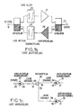
- Two-way communication cable networks used in particular in video communication, are currently formed of two main parts, as well as shown in Figure 1a.
- the first part is made up of a head processing audio or video programs or services, transported by the cable network, and grouping antennas 1, 2, 3 for receiving signals transmitted by terrestrial transmitters, by transmitters on board satellite or radio-relay systems, frequency 4 or modulation 5 to transform the frequency modulation of signals received in modulation amplitude suitable for television receivers, and amplitude modulators 6 for signals locally available in video-frequency and audio-frequency baseband.
- a multiplexer 7 makes it possible to deliver the different signals on an output terminal 8 of the station head. Other signals such as radio broadcasting frequency modulation or services transmitted on carrier modulated by analog or digital modulation can also be forwarded.
- the second part, cable network proper transmits in the form of a radio frequency multiplex the various aforementioned signals.
- the network is generally realized on a physical support constituted by a pair coaxial and has a tree structure. He understands essentially the transport (or distribution) network transmitting the multiplex, delivered by the head station, to distribution areas, this network being made up of a coaxial line 9 with low loss and amplifiers 10 to compensate for these.
- To the transport network one or more distribution networks are associated, interconnected to a compensation amplifier 10 losses via a distribution amplifier 11 and formed by a coaxial distribution line 12 on which passive branch circuits are inserted or distributors 13 to which a connection network formed by a coaxial line 15 is connected.
- Line coaxial 15 is terminated by a user socket 16, which allows to distribute the signals to the terminals 17 of the user.
- the aforementioned cable networks are currently used according to a process of two-way communication, signals or messages being further transmitted to the head station according to a so-called return path.
- the distribution of communication directions in the different coaxial lines making up the cable network is carried out by frequency multiplexing, the band of lower frequency, typically, 5 to 30 MHz being affected to the return channel while the upper frequency band, typically 50 to 860 MHz, is assigned to the channel go.
- Figure 1b the structure of a line amplifier suitable for bidirectional communication, the forward channel comprising an input-output diplexer 19, a correction circuit 20, an amplifier 21, a output diplexer 22, and an output circuit 23, and the return channel, between the two input-output diplexers 19, 22, an amplifier 24, a correction circuit 25.
- Input 18 for the outbound lane is connected to the line coaxial 9 or 12 of Figure 1a, the diplexer 19 ensuring the separation of frequency bands according to their allocation according to the direction of forward or return transmission.
- the output diplexer 22 plays an identical role to the diplexer input 19.
- a power supply not shown, provides the electrical energy essential for supplying amplifiers 21 and 24. Correctors 20 and 25 allow equalize losses as a function of frequency for the way to go respectively the way back.
- FIG. 1c a section of line bursting into two branches from a distributor 30, the bidirectional nature of amplifiers 27, 35 and 39 being symbolized by the empty and full triangles superimposed, symbolizing the amplifiers of the forward path respectively of the return channel shown in Figure 1b.
- Amplifiers 27, 35 and 39 are identical and include for the signals transmitted on the channel go the inputs 26, 36, 40 and outputs 28, 37 and 41 respectively.
- a coaxial line 29 transports the signals to the dispatcher 30, which distributes the input power to input 36 and 40 of the amplifiers 35 and 39, through the lines coaxial 34, 38. Correct operation of the assembly is obtained when the amplifiers compensate for the losses introduced by the corresponding coaxial connections. In Consequently, the electrical power at output 37 and 41 of amplifiers 35 and 39 is identical to the power electrical output 28 of the upstream amplifier 27.
- a reference signal is injected at the head station output and the power in output of each amplifier is adjusted to the same value, proceeding step by step successively, this which involves measurement and adjustment at the geographic location of each amplifier.
- the amplifier 27 cannot compensate for the losses of the link with amplifier 35 and the losses of the connection with amplifier 39, which are not incidentally necessarily identical.
- the process of adjusting the return path is therefore different from that of the outward path and may consist of measuring the power at input 28 of amplifier 27, to act on the corrector 25 figure 1b of the return amplification channel of the upstream amplifier 35 so that this measured power is identical to that which had been measured on input 37 above. Then proceed in the same way for amplifier 39, now the measurement on input 28 of amplifier 27.
- This method therefore appears very cumbersome because it assumes a simultaneous intervention in two places, for example amplifier 35 for injecting a measurement signal reference and action on the corrector of this same amplifier and measurement at input 28 of amplifier 27.
- a first improvement consists in measuring the power level, on the return path, of a carrier at 10 or 30 MHz for example, the measured level being subtracted at a calibration level at this frequency and at the value theoretical gain of the return channel.
- the final result is added to a carrier, transmitted in the band VHF, playing the role of tuning frequency, a carrier of reference being issued in the same band with a level symbolizing the theoretical gain adjustment of the return.
- the adjustment is made when the carrier of reference and the adjustment carrier have the same level, obtained by variation of the gain on the channel amplifier return. This method is satisfactory, but it involves the use of very sophisticated and expensive devices.
- Another improvement is to place in station the device for measuring the power received by the head station from test signals injected into network amplifiers.
- a camera films the reading of corresponding measurement and transmits it in a TV channel of the outward path, where it can be observed by the operator settings.
- This method also involves the use of a sophisticated hardware and does not really allow simplification of the classical method, if not the introduction greater autonomy of the operator site.
- Document NL-A-87 823 describes a method of control of the operation of intermediate amplifiers of a terminal station of a communication system.
- the process described by this document involves the simultaneous sending either of signals at two different carrier frequencies located in the upper frequency band and a product intermodulation in the frequency band lower, either of signals at a single carrier frequency, lying in the lower frequency band and a harmonic product falling in the frequency band superior.
- the object of the present invention is to implement a device for measuring and adjusting the return channel a wired network allowing autonomy and complete independence of the operator from on-site adjustments using the aforementioned device, which may not intervene only in one geographic point for an amplifier given.
- Another object of the present invention is the implementation using a track measurement and adjustment device from a two-way wired communication network allowing an adjustment operator to perform step by step the setting of each amplifier so many the lane go that from the return lane successively from this network.
- Another object of the present invention is the implementation using a track measurement and adjustment device from a wired network using components or common equipment.
- the device for measuring and adjusting signals in return channel of a two-way wired communication network, from test signals, including one channel go and a return path, object of the present invention is remarkable in that it includes a coupling circuit of the measurement and adjustment device to the cable network for taking test signals from the return.
- Frequency converter circuit is interconnected to the coupling circuit and allows translation of the frequency band of the test signals on the return channel in a frequency band of the forward channel to deliver a converted test signal.
- a circuit signal generator with adjustable power is provided for deliver a reference signal having a neighboring frequency that of the converted test signal and a summing circuit independently receives the converted test signal and reference signal and outputs a resulting signal whose frequency is substantially that of the test signal converted.
- the output of the summing circuit is connected to the coupling circuit to reinject at the level of the channel go the resulting signal, which allows to perform the adjustment of the elements of the forward and of the track return.
- the device which is the subject of the present invention finds application to the implementation and maintenance of two-way communication cable networks, such as cable video communication networks.
- the cable network comprises, in a conventional manner, a forward path and a path back under the conditions defined previously in the description, in order to allow communication bidirectional on this network.
- the device object of the present invention comprises a circuit 42 for coupling the measuring device and adjustment to the cable network, this coupling device allowing to take test signals from the return channel.
- a frequency converter circuit 44 is planned, this circuit being interconnected with the coupling 42 and making it possible to translate the frequency band of test signals on the return channel in a forward channel frequency band to deliver a converted test signal.
- STR the test signal on the return channel, which is injected by example at the input of amplifier 51 whose setting must be made, this entry being considered as the input of the return channel of the aforementioned amplifier 51 in the conditions of description of the amplifiers bidirectional used, as described previously in the description.
- the converted test signal is denoted STRC, this converted test signal being delivered in output of circuit 44 frequency converter.
- the device object of the present invention comprises a circuit 50 generator of a reference signal, noted SREF, at adjustable power and frequency, the signal frequency aforementioned reference having a frequency whose value can be adjusted to a value close to that of the signal converted test, STRC.
- SREF reference signal
- the signal frequency aforementioned reference having a frequency whose value can be adjusted to a value close to that of the signal converted test, STRC.
- value close to the frequency of these two signals we mean any distinct value that can be separated by a device such as a spectrum, the frequency difference in relative value between the two signals can for example be rendered also small than 5%.
- the frequency of the reference signal delivered by the generator circuit 50 can also be set to values covering no only the frequency of the converted STRC test signal, but also the frequency band of the forward channel, this at purposes of setting up and using the cable network which will explained later in the description.
- the device which is the subject of the present invention includes a summing circuit 49 independently receiving the converted test signal, STRC, and the reference signal, SREF, and outputting a resulting signal whose frequency is substantially that of the converted test signal when the frequencies of these two signals are close as previously mentioned.
- independent reception the converted STRC test signal and the reference signal SREF means reception by the summing circuit 49 above of these two signals under the multiplexing conditions frequency, either in the same frequency band allocated to the return channel, either with regard to the reference signal as previously mentioned, in the frequency band of the signals allocated to the forward channel.
- the output of the summing circuit 49 is interconnected at an input of the coupling circuit 42, which makes it possible to reinject at the level of the forward path the resulting signal SR above, in order to adjust the track elements go and return path under the conditions that will explained later in the description.
- the resulting signal SR includes the corresponding frequency components with the power levels of the two original signals, converted test signal, STRC, and reference signal, SREF.
- the above circuit can advantageously include in cascade a filter 45 centered on the frequency of test signals, STR, on the return path, these signals test being in the frequency band of the return channel.
- Filter 45 has its input connected to the coupling circuit 42.
- an amplifier 46 with adjustable gain is connected in cascade with filter 45, this amplifier having its output connected to a circuit 47 for changing frequency proper.
- the actual frequency change circuit 47 can be made by any conventional type mixer fitted with a stabilized quartz oscillator for performing frequency change required under conditions of stability and reliability of the frequency value of the converted test signal, STRC.
- the summing circuit 49 has an input connected at the output of the frequency converter circuit 44, or more particularly of circuit 47 for changing frequency proper, via a filter 48 centered on the center frequency of the converted test signal, STRC.
- filters 45 and 48 can be made by suitable filters of the conventional type and of which the response curve is flat and of the bandpass type in the frequency domain allocated to the return channel respectively to the way to go.
- FIGS. 3a, 3b and 3c A more detailed description of a use particularly advantageous of a measuring and tuning of signals in the return path of a cable network two-way communication, as shown in figure 2, will now be given in connection with FIGS. 3a, 3b and 3c.
- the use of the device object of the present invention consists in coupling the aforementioned circuit in the vicinity of the output 8 of the network head station.
- the notion of neighborhood here consists of the notion purely material of the adaptation of the coupling circuit 42 to the output 8 of the headend under the usual conditions interconnection for UHF or VHF signals of bands frequency allocated to the forward channel, respectively to the way back.
- the use object of the present invention then consists in perform a calibration step 100 of the device according to the invention coupled with the output of the head of the network.
- the calibration step was represented by means of a schematic diagram in Figure 3a.
- This calibration step can advantageously include successive stages consisting in performing a step 1000 of injection level of the coupling circuit 42 and in particular of entry 43 thereof located downstream side vis-à-vis the coupling circuit 42 in the direction of propagation of the forward channel, a test signal in the frequency band of the way back.
- this test signal says calibration test signal, is a calibrated signal both in power level only in frequency.
- step 1000 is then followed by a step 1001 for measuring the power of the converted signal delivered by the frequency converter circuit 44, this measurement being performed after transmission by the summing circuit 49 and by the coupling circuit 42, that is to say at the level of the input or injection point 43 of the test signal calibration, STE.
- This measure is of course possible without difficulty for the operator, since the test signal converted is frequency duplexed by the summing circuit 49, the center frequency of this converted signal being good heard in the frequency band allocated to the forward channel.
- step 1001 can then be followed by a gain adjustment by amplifier 46 to obtain a sufficient power level at terminal 43 of the coupling circuit 42, to allow measurement satisfactory of it.
- step 1002 can then be followed by a step 1003 of adjusting the power of the reference signal SREF at a power level determined in relation to the power level of the converted calibration test signal.
- This determined power level can be expressed in dB at a value taking into account in particular the attenuation differences undergone by the calibration test signal and by the reference signal, due to their different course in the device object of the present invention.
- adjusting the gain of amplifier 46 takes a power difference between the level of the reference signal and the level of the reconverted calibration test signal equal at 0 dB.
- step 1003 of the calibration phase, 100 can then be followed by the adjustment step cable network amplifiers, denoted 200 in the figure 3a, which will be described in more detail in connection with the Figure 3b.
- step 200 described in conjunction with the Figures 3a and 3b can be performed after adjusting the channel go, for example.
- step 200 of adjusting the amplifiers of the wired network consists, for any amplifier of rank k, the setting of the forward channel of the row amplifiers anterior being performed, to be injected at the input of all return channel amplifier, a test signal same power as the calibration test signal used for the calibration phase.
- the test signal, noted STR, injected at the input of the amplifier 51 in Figure 2 will also have the same frequency that the calibration test signal used for perform the calibration step previously described.
- the stage of injection has the reference 2001 in FIG. 3b.
- This injection step is followed by a step 2002 consisting of measure the power difference between the test signal converted, STRC, and the reference signal, SREF, these signals being of course received following the coupling by the circuit of coupling 42 via the forward path of amplifier 51 and being thus measured at the output of this forward path, that is to say at the entrance, and therefore at the same operator intervention point of the return channel of this same amplifier 51.
- This injection and this measurement can be performed by the operator using conventional type devices.
- step 2002 is then followed by a step 2003 adjustment of loss correctors back to obtain a power difference identical to that measured during the calibration step between the test signal converted calibration and reference signal.
- step 2003 adjustment of loss correctors back to obtain a power difference identical to that measured during the calibration step between the test signal converted calibration and reference signal.
- the device object of the present invention allows, the adjustment of the forward path having been done beforehand, or setting a portion of this, to carry out step by step the adjustment of return channels of the corresponding amplifiers, and this in the direction of propagation of the outward path.
- the settings for the outbound route and the return route or a portion of these channels can be performed successively for each amplifier and step by step in the direction of propagation of the outward path, as will be described below in conjunction with Figure 3c.
- the actual adjustment step 200 can be carried out in two sub-steps, noted 200a and 200b, the step 200a consisting of an adjustment of the forward channel from the reference signal, for example, and step 200b consisting adjusting the return channel according to process 200 of the Figure 3b.
- steps 200a and 200b are carried out on the bidirectional head amplifier, i.e. the bidirectional amplifier located nearby immediately from exit 8 of the station head, then successively and step by step, for amplifiers of rank k-1, k, k + 1 and so on over all or part of the network to be paid.
- the device object of the present invention can then advantageously include, as shown in FIG. 4, a circuit 52 for decoding a control signal, denoted SC, this control signal, SC, being injected by the operator at amplifier return channel input level 51 transmitted by this return channel not yet set, then by the coupler circuit 42, finally by the filter 45.
- This control signal SC can advantageously consist of a signal modulating pulses the channel test signal back, STR, or a fraction of the power thereof of course, this coded control signal allowing on decoding by the decoding circuit 52 a command from the transmission frequency of oscillator 50 and finally of frequency of the reference signal, SREF.
- control signal injected at the input of the return from amplifier 51 is transmitted with reliability and sufficient precision from the point of view of coding by the return channel of amplifier 51, although this not yet set, so control the frequency of the reference signal, either to the value of one or more forward channel frequencies for tuning of the go channel of the amplifier 51, and then the control of oscillator 50 to generate the signal SREF reference in view, either of the calibration phase, or the successive adjustment of the amplifiers of higher rank.
- the adjustment of the way out and back way can be as well performed at each successive row amplifier during a single geographic displacement on the amplifier site considered for the operator performing the adjustment.
- the injection of different signals for the calibration and actual adjustment can be carried out by conventional means which can be a filter diplexer comprising an input transmitting the frequency band of the return channel, typically 10 to 30 MHz, at which is connected a test signal generator, an input transmitting the frequency band of the forward channel, typically from 50 to 860 MHz, to which a power measurement circuit such as a spectrum or Wattmeter, and a coupling output transmitting the two frequency bands which is connected to the amplifier in adjustment.
- a filter diplexer comprising an input transmitting the frequency band of the return channel, typically 10 to 30 MHz, at which is connected a test signal generator, an input transmitting the frequency band of the forward channel, typically from 50 to 860 MHz, to which a power measurement circuit such as a spectrum or Wattmeter, and a coupling output transmitting the two frequency bands which is connected to the amplifier in adjustment.
Landscapes
- Engineering & Computer Science (AREA)
- Computer Networks & Wireless Communication (AREA)
- Signal Processing (AREA)
- Monitoring And Testing Of Transmission In General (AREA)
Claims (6)
- Einrichtung zum Messen und Regulieren von Rückwegsignalen eines einen Hinweg und einen Rückweg umfassenden bidirektionalen Kabelkommunikationsnetzes vermittels Testsignalen, dadurch gekennzeichnet, daß die Einrichtung umfaßt:Koppelmittel (42) zum Koppeln der Meß- und Reguliereinrichtung mit dem Kabelnetz, wobei es die Koppelmittel (42) erlauben, die Testsignale auf dem Rückweg (STR) abzugreifen, und verbunden mit den Koppelmitteln (42)Frequenzwandlermittel (44), welche mit den Koppelmitteln (42) verschaltet sind und es erlauben, eine Umsetzung des Frequenzbands der Testsignale auf dem Rückweg (STR) in ein Frequenzband des Hinwegs durchzuführen, um ein umgewandeltes Testsignal (STRC) zu liefern,Generatormittel (50) zum Erzeugen eines Referenzsignals (SREF) einstellbarer Energie, wobei das Referenzsignal (SREF) eine Frequenz besitzt, die derjenigen des umgewandelten Testsignals (STRC) benachbart ist,Summationsmittel (49), welche das umgewandelte Testsignal (STRC) sowie das Referenzsignal (SREF) unabhängig voneinander erhalten und ausgangsseitig ein resultierendes Signal (STEC) liefern, dessen Frequenz im wesentlichen diejenige des umgewandelten Testsignals ist, wobei der Ausgang der Summationsmittel (49) mit den Koppelmitteln (42) verbunden ist, um das resultierende Signal (STEC) wieder in den Hinweg einzuspeisen, was es erlaubt, die Regulierung der Elemente des Hinwegs und des Rückwegs durchzuführen.
- Einrichtung nach Anspruch 1, dadurch gekennzeichnet, daß die Frequenzwandlermittel (44) in Kaskade umfassen:ein Filter (45), welches auf die Frequenz der im Frequenzband des Rückwegs liegenden Testsignale (STR) zentriert ist, wobei der Eingang des Filters (45) mit den Koppelmitteln (42) verbunden ist,einen Verstärker (46) mit regulierbarem Verstärkungsfaktor, wobei der Ausgang des Verstärkers (46) mit einer Schaltung (47) zur eigentlichen Frequenzänderung verbunden ist.
- Einrichtung nach Anspruch 1 oder 2, dadurch gekennzeichnet, daß die Summationsmittel (49) einen Eingang besitzen, welcher unter Zwischenschaltung eines auf die Mittenfrequenz des Frequenzbands des umgewandelten Testsignals (STRC) zentrierten Filters (48) mit dem Ausgang der Frequenzänderungsschaltung (47) verbunden ist.
- Verwendung einer Einrichtung zum Messen und Regulieren von Rückwegsignalen eines bidirektionalen Kabelkommunikationsnetzes nach einem der Ansprüche 1 bis 3, dadurch gekennzeichnet, daß die Verwendung umfaßt:die Einrichtung in der Nähe des Ausgangs der Kopfstation des Netzes anzukoppeln undeinen Schritt (100) zum Abgleichen der Einrichtung durchzuführen, wobei dieser Abgleichschritt umfaßt,ein Abgleichtestsignal (STR) im Frequenzband des Rückwegs in die Koppelmittel (42) einzuspeisen (1000),die Energie des von den Frequenzwandlermitteln (44) gelieferten umgewandelten Signals (STRC) im Bereich des Einspeisungspunkts (43) zu messen (1001),den Verstärkungsfaktor des Verstärkers (46) zu justieren (1002), um eine hinreichende Energiehöhe zu erreichen,die Energie des Referenzsignals (SREF) auf eine Energiehöhe einzustellen (1003), die in bezug auf die Energiehöhe des umgewandelten Testsignals (STRC) festgelegt ist, unddie Regulierung der Verstärker des Kabelnetzes nach der Abgleichphase durchzuführen (200).
- Verwendung nach Anspruch 4, dadurch gekennzeichnet, daß der Schritt der Durchführung der Regulierung der Verstärker des Kabelnetzes nach der Regulierung des Hinwegs umfaßt:am Eingang jedes Verstärkers des Rückwegs ein Testsignal (STR) gleicher Energie wie das für die Abgleichphase benutzte Testsignal einzuspeisen (2001),die Abweichung der Energie zwischen dem umgewandelten Testsignal (STRC) und dem Referenzsignal (SREF) zu messen (2002),die Verlustausgleicher dieses Verstärkers des Rückwegs zu justieren, um eine Abweichung zu erhalten, die identisch zu der beim Abgleich gemessenen ist.
- Verwendung nach einem der Ansprüche 4 oder 5, dadurch gekennzeichnet, daß die Regulierungen des Hinwegs und des Rückwegs nacheinander und schrittweise für jeden Verstärker in Ausbreitungsrichtung des Hinwegs durchgeführt werden, wobei so die Regulierung des Hinwegs und des Rückwegs im Bereich jedes Verstärkers im Zuge ein und derselben geographischen Verlagerung an der Stelle des betrachteten Verstärkers durchgeführt wird.
Applications Claiming Priority (2)
| Application Number | Priority Date | Filing Date | Title |
|---|---|---|---|
| FR9212472A FR2697118B1 (fr) | 1992-10-19 | 1992-10-19 | Dispositif de mesure et de réglage des signaux en voie de retour d'un réseau câblé de communication bidirectionnelle, et son utilisation. |
| FR9212472 | 1992-10-19 |
Publications (2)
| Publication Number | Publication Date |
|---|---|
| EP0594487A1 EP0594487A1 (de) | 1994-04-27 |
| EP0594487B1 true EP0594487B1 (de) | 1998-05-27 |
Family
ID=9434657
Family Applications (1)
| Application Number | Title | Priority Date | Filing Date |
|---|---|---|---|
| EP19930402548 Expired - Lifetime EP0594487B1 (de) | 1992-10-19 | 1993-10-15 | Einrichtung zur Messung und Regelung von Signalen auf der Rückleitung eines bidirektionellen Kommunikationsnetzwerkes und ihre Anwendung |
Country Status (3)
| Country | Link |
|---|---|
| EP (1) | EP0594487B1 (de) |
| DE (1) | DE69318795T2 (de) |
| FR (1) | FR2697118B1 (de) |
Families Citing this family (2)
| Publication number | Priority date | Publication date | Assignee | Title |
|---|---|---|---|---|
| DE19536682A1 (de) * | 1995-09-30 | 1997-04-03 | Sel Alcatel Ag | Übertragungssystem mit Übergabeeinrichtungen, die Auswirkungen von Störungen reduzieren |
| CN110311877B (zh) * | 2019-07-05 | 2022-03-01 | 北京神经元网络技术有限公司 | 多子频带信号传输方法、装置、设备及介质 |
Family Cites Families (2)
| Publication number | Priority date | Publication date | Assignee | Title |
|---|---|---|---|---|
| NL87823C (de) * | 1900-01-01 | |||
| JPH01192229A (ja) * | 1988-01-27 | 1989-08-02 | Furukawa Electric Co Ltd:The | 双方向catv用中継増幅器 |
-
1992
- 1992-10-19 FR FR9212472A patent/FR2697118B1/fr not_active Expired - Fee Related
-
1993
- 1993-10-15 DE DE1993618795 patent/DE69318795T2/de not_active Expired - Fee Related
- 1993-10-15 EP EP19930402548 patent/EP0594487B1/de not_active Expired - Lifetime
Also Published As
| Publication number | Publication date |
|---|---|
| FR2697118B1 (fr) | 1995-01-06 |
| FR2697118A1 (fr) | 1994-04-22 |
| DE69318795D1 (de) | 1998-07-02 |
| DE69318795T2 (de) | 1999-01-14 |
| EP0594487A1 (de) | 1994-04-27 |
Similar Documents
| Publication | Publication Date | Title |
|---|---|---|
| FR2662895A1 (fr) | Installation de distribution de programmes de radiodiffusion a reseau cable. | |
| EP0040127B1 (de) | Signalübertragungsanordnung mit einer Schaltung zur Vorkorrektur nichtlinearer Produkte | |
| FR2750258A1 (fr) | Systeme de conformation de faisceau zonal reconfigurable pour une antenne embarquee sur un satellite en orbite et procede d'optimisation de la reconfiguration | |
| EP0808529A1 (de) | Verfahren und anordnung zur verminderung von funkstörungen und anwendung in einem interaktiven fernsehsystem | |
| EP1175741B1 (de) | Bidirektionales multimediakommunikationsendgerät | |
| EP1170823B1 (de) | Telekommunikationsantenne mit grossem Erdabdekkungsbereich | |
| FR2778802A1 (fr) | Dispositif d'emission et de reception d'ondes hyperfrequences polarisees circulairement | |
| EP0120742B2 (de) | Videokommunikationskabelnetzwerk | |
| EP0594487B1 (de) | Einrichtung zur Messung und Regelung von Signalen auf der Rückleitung eines bidirektionellen Kommunikationsnetzwerkes und ihre Anwendung | |
| FR3078600A1 (fr) | Procedes d'emission et de reception d'un signal radiofrequence dans un systeme de transmission par satellite, emetteur, recepteur de caracterisation et programme d'ordinateur correspondants. | |
| EP1331749A1 (de) | Mehrfachsignalübertragungs auf ein Koaxialkabel | |
| EP0118357B1 (de) | Elektronisches Antennensystem für ein zellulares Funktelefonnetz mit ortsfesten Basisstationen und mit beweglichen sowie mit tragbaren Teilnehmergeräten | |
| EP3975434A1 (de) | System und verfahren zur unterdrückung von aufwärts gerichteten störsignalen, die in einem mehrpunkt-raumkommunikationssystem erzeugt werden | |
| EP0991215B1 (de) | Aperiodisches modulares System zur Übertragungswiederholung mit mehreren digitalen Kanälen | |
| FR2559976A1 (fr) | Systeme rayonnant pour la radiodiffusion dans les tunnels routiers et equipement d'alimentation de ce systeme | |
| EP0438934B1 (de) | Verteilungssystem für Signale sehr hoher Frequenz | |
| EP0552094A1 (de) | Mehrnormrundfunkstation für herkömmliches Fernsehen und HDTV beim terrestrische Netzwerk | |
| FR2515400A1 (fr) | Installation de telesurveillance | |
| FR2530394A1 (fr) | Dispositif de multiplexage et de demultiplexage de voies video | |
| FR2778803A1 (fr) | Circuit et procede de reception ou d'emission d'ondes hyperfrequences | |
| JPH07107328A (ja) | 共同聴視施設及び分岐増幅装置 | |
| FR2794330A1 (fr) | Voie modulaire de traitement pour la reemission d'un signal radiofrequence de television analogique et numerique et systeme mettant en oeuvre cette voie de traitement | |
| FR2675604A1 (fr) | Reseau local multipoint permettant la transmission de signaux audiovisuels. | |
| BE571515A (de) | ||
| KR20040104167A (ko) | 케이블 티브이망을 이용한 통신 시스템에 있어서의 노이즈 필터링 및 신호 증폭 장치 |
Legal Events
| Date | Code | Title | Description |
|---|---|---|---|
| PUAI | Public reference made under article 153(3) epc to a published international application that has entered the european phase |
Free format text: ORIGINAL CODE: 0009012 |
|
| AK | Designated contracting states |
Kind code of ref document: A1 Designated state(s): BE DE ES GB NL SE |
|
| 17P | Request for examination filed |
Effective date: 19940328 |
|
| 17Q | First examination report despatched |
Effective date: 19970206 |
|
| GRAG | Despatch of communication of intention to grant |
Free format text: ORIGINAL CODE: EPIDOS AGRA |
|
| GRAG | Despatch of communication of intention to grant |
Free format text: ORIGINAL CODE: EPIDOS AGRA |
|
| GRAH | Despatch of communication of intention to grant a patent |
Free format text: ORIGINAL CODE: EPIDOS IGRA |
|
| GRAH | Despatch of communication of intention to grant a patent |
Free format text: ORIGINAL CODE: EPIDOS IGRA |
|
| GRAA | (expected) grant |
Free format text: ORIGINAL CODE: 0009210 |
|
| AK | Designated contracting states |
Kind code of ref document: B1 Designated state(s): BE DE ES GB NL SE |
|
| PG25 | Lapsed in a contracting state [announced via postgrant information from national office to epo] |
Ref country code: ES Free format text: THE PATENT HAS BEEN ANNULLED BY A DECISION OF A NATIONAL AUTHORITY Effective date: 19980527 |
|
| REF | Corresponds to: |
Ref document number: 69318795 Country of ref document: DE Date of ref document: 19980702 |
|
| GBT | Gb: translation of ep patent filed (gb section 77(6)(a)/1977) |
Effective date: 19980612 |
|
| PG25 | Lapsed in a contracting state [announced via postgrant information from national office to epo] |
Ref country code: SE Free format text: LAPSE BECAUSE OF FAILURE TO SUBMIT A TRANSLATION OF THE DESCRIPTION OR TO PAY THE FEE WITHIN THE PRESCRIBED TIME-LIMIT Effective date: 19980827 |
|
| PLBE | No opposition filed within time limit |
Free format text: ORIGINAL CODE: 0009261 |
|
| STAA | Information on the status of an ep patent application or granted ep patent |
Free format text: STATUS: NO OPPOSITION FILED WITHIN TIME LIMIT |
|
| 26N | No opposition filed | ||
| REG | Reference to a national code |
Ref country code: GB Ref legal event code: IF02 |
|
| PGFP | Annual fee paid to national office [announced via postgrant information from national office to epo] |
Ref country code: GB Payment date: 20020927 Year of fee payment: 10 |
|
| PGFP | Annual fee paid to national office [announced via postgrant information from national office to epo] |
Ref country code: NL Payment date: 20020930 Year of fee payment: 10 Ref country code: BE Payment date: 20020930 Year of fee payment: 10 |
|
| PGFP | Annual fee paid to national office [announced via postgrant information from national office to epo] |
Ref country code: DE Payment date: 20021015 Year of fee payment: 10 |
|
| PG25 | Lapsed in a contracting state [announced via postgrant information from national office to epo] |
Ref country code: GB Free format text: LAPSE BECAUSE OF NON-PAYMENT OF DUE FEES Effective date: 20031015 |
|
| PG25 | Lapsed in a contracting state [announced via postgrant information from national office to epo] |
Ref country code: BE Free format text: LAPSE BECAUSE OF NON-PAYMENT OF DUE FEES Effective date: 20031031 |
|
| BERE | Be: lapsed |
Owner name: *TELEDIFFUSION DE FRANCE Effective date: 20031031 |
|
| PG25 | Lapsed in a contracting state [announced via postgrant information from national office to epo] |
Ref country code: NL Free format text: LAPSE BECAUSE OF NON-PAYMENT OF DUE FEES Effective date: 20040501 Ref country code: DE Free format text: LAPSE BECAUSE OF NON-PAYMENT OF DUE FEES Effective date: 20040501 |
|
| GBPC | Gb: european patent ceased through non-payment of renewal fee |
Effective date: 20031015 |
|
| NLV4 | Nl: lapsed or anulled due to non-payment of the annual fee |
Effective date: 20040501 |