EP0594542A1 - Attache pour élément de couverture plat - Google Patents
Attache pour élément de couverture plat Download PDFInfo
- Publication number
- EP0594542A1 EP0594542A1 EP93810741A EP93810741A EP0594542A1 EP 0594542 A1 EP0594542 A1 EP 0594542A1 EP 93810741 A EP93810741 A EP 93810741A EP 93810741 A EP93810741 A EP 93810741A EP 0594542 A1 EP0594542 A1 EP 0594542A1
- Authority
- EP
- European Patent Office
- Prior art keywords
- clamping
- profile
- clamping part
- spring
- holder according
- Prior art date
- Legal status (The legal status is an assumption and is not a legal conclusion. Google has not performed a legal analysis and makes no representation as to the accuracy of the status listed.)
- Withdrawn
Links
- 230000000284 resting effect Effects 0.000 claims abstract description 4
- 238000004873 anchoring Methods 0.000 claims 1
- 238000010276 construction Methods 0.000 abstract description 5
- 238000009435 building construction Methods 0.000 abstract description 4
- 230000000694 effects Effects 0.000 description 8
- 229910052782 aluminium Inorganic materials 0.000 description 4
- XAGFODPZIPBFFR-UHFFFAOYSA-N aluminium Chemical compound [Al] XAGFODPZIPBFFR-UHFFFAOYSA-N 0.000 description 4
- 239000012792 core layer Substances 0.000 description 4
- 239000000725 suspension Substances 0.000 description 4
- 229910000838 Al alloy Inorganic materials 0.000 description 3
- 239000004033 plastic Substances 0.000 description 3
- 229920003023 plastic Polymers 0.000 description 3
- -1 polyethylene Polymers 0.000 description 3
- XEEYBQQBJWHFJM-UHFFFAOYSA-N Iron Chemical compound [Fe] XEEYBQQBJWHFJM-UHFFFAOYSA-N 0.000 description 2
- 239000004698 Polyethylene Substances 0.000 description 2
- 229910000639 Spring steel Inorganic materials 0.000 description 2
- 229910000831 Steel Inorganic materials 0.000 description 2
- 238000004026 adhesive bonding Methods 0.000 description 2
- 239000002131 composite material Substances 0.000 description 2
- 230000001419 dependent effect Effects 0.000 description 2
- 239000011521 glass Substances 0.000 description 2
- 230000007774 longterm Effects 0.000 description 2
- 229910052751 metal Inorganic materials 0.000 description 2
- 239000002184 metal Substances 0.000 description 2
- 229920000573 polyethylene Polymers 0.000 description 2
- 239000010959 steel Substances 0.000 description 2
- XLYOFNOQVPJJNP-UHFFFAOYSA-N water Chemical compound O XLYOFNOQVPJJNP-UHFFFAOYSA-N 0.000 description 2
- 241001136792 Alle Species 0.000 description 1
- RYGMFSIKBFXOCR-UHFFFAOYSA-N Copper Chemical compound [Cu] RYGMFSIKBFXOCR-UHFFFAOYSA-N 0.000 description 1
- 241001295925 Gegenes Species 0.000 description 1
- 239000004952 Polyamide Substances 0.000 description 1
- 230000001154 acute effect Effects 0.000 description 1
- 238000005452 bending Methods 0.000 description 1
- 230000015572 biosynthetic process Effects 0.000 description 1
- 239000000919 ceramic Substances 0.000 description 1
- 239000010949 copper Substances 0.000 description 1
- 229910052802 copper Inorganic materials 0.000 description 1
- 239000000428 dust Substances 0.000 description 1
- 230000005489 elastic deformation Effects 0.000 description 1
- 238000007373 indentation Methods 0.000 description 1
- 229910052742 iron Inorganic materials 0.000 description 1
- 230000002427 irreversible effect Effects 0.000 description 1
- 238000004519 manufacturing process Methods 0.000 description 1
- 239000000463 material Substances 0.000 description 1
- 238000000034 method Methods 0.000 description 1
- 229920002647 polyamide Polymers 0.000 description 1
- 230000007704 transition Effects 0.000 description 1
- 238000003466 welding Methods 0.000 description 1
Images



Classifications
-
- E—FIXED CONSTRUCTIONS
- E04—BUILDING
- E04D—ROOF COVERINGS; SKY-LIGHTS; GUTTERS; ROOF-WORKING TOOLS
- E04D3/00—Roof covering by making use of flat or curved slabs or stiff sheets
- E04D3/36—Connecting; Fastening
- E04D3/3605—Connecting; Fastening of roof covering supported directly by the roof structure
-
- E—FIXED CONSTRUCTIONS
- E04—BUILDING
- E04D—ROOF COVERINGS; SKY-LIGHTS; GUTTERS; ROOF-WORKING TOOLS
- E04D3/00—Roof covering by making use of flat or curved slabs or stiff sheets
- E04D3/36—Connecting; Fastening
-
- F—MECHANICAL ENGINEERING; LIGHTING; HEATING; WEAPONS; BLASTING
- F16—ENGINEERING ELEMENTS AND UNITS; GENERAL MEASURES FOR PRODUCING AND MAINTAINING EFFECTIVE FUNCTIONING OF MACHINES OR INSTALLATIONS; THERMAL INSULATION IN GENERAL
- F16B—DEVICES FOR FASTENING OR SECURING CONSTRUCTIONAL ELEMENTS OR MACHINE PARTS TOGETHER, e.g. NAILS, BOLTS, CIRCLIPS, CLAMPS, CLIPS OR WEDGES; JOINTS OR JOINTING
- F16B2/00—Friction-grip releasable fastenings
- F16B2/02—Clamps, i.e. with gripping action effected by positive means other than the inherent resistance to deformation of the material of the fastening
- F16B2/06—Clamps, i.e. with gripping action effected by positive means other than the inherent resistance to deformation of the material of the fastening external, i.e. with contracting action
- F16B2/065—Clamps, i.e. with gripping action effected by positive means other than the inherent resistance to deformation of the material of the fastening external, i.e. with contracting action using screw-thread elements
Definitions
- the invention relates to a holder for flat cover elements with at least one angled leg on essentially T or L-shaped profiles of a substructure.
- the raw walls and ceilings of buildings are increasingly clad with curtain-like, plate-shaped elements that are hung in a ventilated manner.
- the curtain wall surfaces give protection from the weather and also have a decorative effect.
- the focus is on the decorative function.
- the dimensions of the elements depend on the character of the building, they are generally about 20-120 cm wide and extend over at least part of the height of one floor, over several floors or even over the entire height of the building. Between the boards, about 1 cm wide joints are left open, which in addition to their effect as expansion joints also act as shadow joints and achieve a decorative effect. In the outside area, the joints are sealed below the surface or, with no effect as shadow joints, provided with a clip-on cover strip, for example. The latter can develop an independent decorative effect.
- Thin facade, wall or ceiling elements are usefully folded at least on their long sides. With cassette ceilings, for example, all four long sides of the elements can also be folded.
- the bevels are used for attachment to the substructure, which in turn is attached to the raw wall or ceiling.
- Known substructures consist, for example, of suspension bolts or suspension rails with corresponding bolts.
- the facade, wall or ceiling elements are suspended via angled grooves in the folds.
- the bolts and the grooves have to be made exactly according to a plan. In the event of inaccuracies, bolts have to be moved and / or grooves refined, which is not only tedious but also costly.
- C2 3048152 a plate holder for facade or roof structures is proposed, which consists of a profile bar and at least one anchor held in its holding position in this with an internal thread for screwing in a screw and a hammer-head-like foot provided with anti-rotation means.
- This foot engages in an undercut groove of the profile bar and is clamped to the profile bar while deforming a clamping part.
- the clamping part located outside the groove is resilient and has at least one locking lug, which is locked in the holding position at a point present in the profile of the profile bar.
- This plate holder for example, multiple glass plates and insulating plates can be attached without having to adjust the position of the holders.
- the holder according to DE, C2 3048152 would be too complicated and too expensive to hold folded facade, wall or ceiling elements, moreover the elements would have to be folded twice in the form of a U instead of simply in the form of an L.
- Covers are also used in numerous areas other than building construction, for example in apparatus construction and in the construction of electrical boxes.
- the inventor has set itself the task of creating a bracket of the type mentioned, which avoids an adjustment of the substructure and / or hanging on covers in general, which should result in a saving in assembly time, an increase in ease of assembly and an improvement in assembly precision .
- the pivotable clamping part is designed as an angled clamping profile.
- a mounting spring preferably a leaf spring, is arranged between this clamping profile and the holding profile, and generates the opening prestress in the clamping piece.
- This relatively strong assembly spring preferably made of stainless spring steel, has another function in addition to the assembly aid, it serves to compensate for tension.
- the pivotable clamping part is designed as a rounded clamping spring, preferably also made of stainless spring steel. It works in a similar way to the angled clamping profile and can also be supplemented by an assembly spring.
- the clamping spring is deformed in the last phase of the tensioning process in addition to swiveling, i.e. slightly bent.
- the clamping spring can also be supported by an angled clamping profile.
- the pivoting movement of the clamping part is preferably carried out via a pivot bearing.
- a pivot bearing is formed on the holding profile and a pivot cylinder forming the pivot axis is formed on the clamping part.
- the swivel cylinder is pushed in the axial direction into the swivel bearing which is open on the longitudinal side at an angle of, for example, approximately 90 °.
- the pivot bearing can also be molded onto the clamping part and the correspondingly designed pivot cylinder into the holding profile. The opening movement is limited by appropriately designed stop surfaces.
- the clamping part can be designed as a clamping spring which is fixedly held at one end in the holding profile, for example in a slot.
- this attachment does not allow any pivoting movement, the clamping spring is closed exclusively by elastic deformation, that is to say by bending.
- Special attention must be paid to the transition from the fixed to the free clamping spring, with known design measures to prevent the clamping spring from being kinked. This is done, for example, by placing it on a correspondingly rounded contact surface.
- the pivoting end of the clamping part which produces the clamping effect brings about a force fit with the tab of the U, T or L profile of the substructure projecting into the clamping piece.
- the free end mentioned is preferably formed at an acute angle in the direction of the flap of the U, T or L profile, with the formation of a press-in lug.
- the push-in lug this is essential, can be designed not only in one piece, but also as a clip-on, screw-on or otherwise fastened spring part, for example as a flat spring.
- the notch created in the flap of the U, T or L profile when clamped creates a positive fit in addition to the frictional connection, which loses its effectiveness more slowly in the long term than a pure frictional connection.
- the clamping effect is preferably generated by means of a clamping screw, which fixes the clamping piece at any location on the surface cover. Both the clamping piece itself and the head of the clamping screw are hidden. Depending on the dimensions of the elements and their mechanical strength, the clamping pieces are arranged at an appropriate distance.
- the screw heads are tightened with a special tool or a shortened Allen key.
- the flat covering elements consist of a metal, for example aluminum, an aluminum alloy, copper, iron or steel, a plastic or a composite material, for example a core layer made of plastic and top surfaces made of aluminum sheets.
- a metal for example aluminum, an aluminum alloy, copper, iron or steel
- a plastic or a composite material for example a core layer made of plastic and top surfaces made of aluminum sheets.
- Such composite materials are known, for example, under the name ALUCOBOND from Alusuisse-Lonza AG.
- ALUCOBOND Alusuisse-Lonza AG.
- facade elements for example, a 2 - 3 mm thick core layer with 0.2 - 0.5 mm thick cover sheets made of an aluminum alloy is used. These covers are folded, on one, two or all around on all four sides (cassettes), or an angled leg is attached accordingly, e.g. by welding, riveting or gluing. The leg can also be replaced by spaced elbows.
- the cover elements can consist of a material that is difficult or not flexible, e.g. from ceramic plates, glass plates or wooden plates. At least one side of the plate has an angled leg attached by gluing, screwing, etc. for receiving the clamping piece.
- the substructure, the holding profile and the clamping profile preferably consist of a metal, such as aluminum, an aluminum alloy or steel, or of a plastic with high mechanical strength and low flow properties, such as a polyethylene or a polyamide.
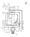
- a folded facade element 10 which could also be a wall or ceiling element, is shown on a substructure with a T-shaped profile 12.
- the facade element 10 consists of a core layer 14 made of polyethylene and two cover plates 16 made of aluminum. In the present case, the cover plates are approximately 0.2 mm thick and the core layer approximately 3 mm thick.
- a bore 20 with a conical bevel for a screw head is cut out at any point perpendicular to the plane of the drawing.
- the distance of the bore 20 from the end face 22 of the bend 18 corresponds approximately to the distance of the bore 24 in the holding profile 26 of a clamping piece 28 from the end face 30 thereof.
- the clamping piece 28 includes a clamping part which is designed as a clamping profile 32 and is approximately rectangular.
- the holding profile 26 and the clamping profile 32 have a wall thickness of approximately 3 mm
- the clamping profile 32 has an angle ⁇ of approximately 85 °.
- the pivotable end 34 of the clamping profile 32 has an acute-angled push-in lug 38 in the direction of a leg 36 of the T-shaped profile 12.
- the pivot axis A of the clamping profile 32 is formed by an integrally formed pivot cylinder 40 which is inserted into a correspondingly designed pivot bearing 42 which is integrally formed on the holding profile 26. Stop surfaces 44 limit the opening movement of the clamping profile 32.
- a clamping screw 46 serves to close the clamping piece 28.
- the screw head 48 which is countersunk in the bore 20 of the fold 18 of the facade element 10, has an Allen hole 50, into which a suitable tool for turning the clamping screw 46 can be inserted.
- a screw shaft 52 passes through the bevel 18, the bore 24 of the holding profile 26, an elongated hole 54 of a mounting spring 56 designed as a leaf spring and an elongated hole 58 of the clamping profile 32.
- the end of the screw shaft 52 facing away from the screw head 48 has an external thread 60.
- a non-rotatable nut 62 which is also shown in FIG. 7, is placed on the external thread 60.
- the essentially rod-shaped screw nut 62 has narrowed ends 64 resting on the clamping profile 32 at both ends and a central part 66 which, to secure the rotation, projects into the elongated hole 58 of the clamping piece 32.
- the screw nut 62 is essentially cylindrical. However, it can be of any shape, it is only essential that a central part 66 can engage in the slot 58 to form the rotation lock. It is also advantageous that the ends 64 of the nut 62 are rounded at least in the direction of the clamping profile 32, so that there is a continuous support at every pivot angle.
- the clamping profile 32 When tightening the clamping screw 46 with the longitudinal axis L, the clamping profile 32 is pivoted against the resistance of the mounting spring 56 and finally the push-in lug 38 is pressed into the leg 36, which rests on the end faces 22 of the fold 18 of the facade element 10 and the end face 30 of the holding profile 26. At the end of the tensioning movement, the swivel profile 32 is also slightly deformed. The indentation in the leg 36 produced by the pressing-in lug 38 brings about a form fit, which ensures a secure hold even if the tensioning force of the tensioning profile 32 is reduced over the long term.
- the leg of the clamping profile 32 comprising the pivotable end 34 can be designed so long that the press-in lug 38 acts on the leg 36 above the bevel 18. It is essential that no torque can act on the clamping piece 28.
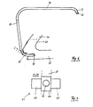
- Fig. 3 shows a clamping spring 74, which is longer compared to the mounting spring 56 of FIG. 2 and bent at the free end 72.
- the push-in nose 38 is formed in a serrated shape, which serrations 76 (FIG. 5) form a positive fit when tensioned with the leg 36 (FIGS. 1, 2).
- the mounting spring 56 can therefore partially replace the clamping profile 32 (Fig. 1, 2). This is not shown in Fig. 3.
- the open position of the clamping spring 74 is indicated by dashed lines.
- a clamping spring 74 without a push-in lug 38 can also be a mounting spring 56.
- FIG. 4 shows a clamping spring 74 which is so strong that it does not require a supporting clamping profile 32 according to FIGS. 1, 2.
- the clamping spring 74 is fastened in a longitudinal slot of a swivel cylinder 40 in accordance with these figures.
- the clamping spring 74 has an elongated hole 58, which is penetrated by the clamping screw.
- a screw nut 62 acts analogously to a clamping profile 32 (FIGS. 1, 2).
- the clamping spring 74 When the clamping piece closes, the clamping spring 74 is initially pivoted about the axis of rotation of the pivot cylinder 40 and then deformed to generate the contact pressure.
- the tines 76 of the push-in lug 38 shown in FIG. 5 are pressed into the leg 36 of the T-shaped profile 12 (FIG. 1).
- FIG. 6 essentially corresponds to that of FIG. 5, but is fastened in a longitudinal slot 78 of the holding profile 26 instead of in a swivel cylinder.
- the tensioning screw 46 (not shown) (FIG. 1, 2) is tightened, the part of the clamping spring 40 emerging from the longitudinal slot 78 "wraps" elastically around a curved surface 80 of the web 68 formed on the holding profile 26. This avoids that in the Clamping spring 74 can cause an irreversible kink.
- FIG. 7 shows a screw nut 62 of a clamping piece 28 with a multi-point push-in lug 38 (cf. FIG. 5), which form a positive connection for the substructure with T-shaped profiles.
- the clamping spring 38 is held down at the free, pivotable end 34 of the clamping profile 32. 8 corresponds to FIGS. 1, 2.
Landscapes
- Engineering & Computer Science (AREA)
- Mechanical Engineering (AREA)
- Architecture (AREA)
- Civil Engineering (AREA)
- Structural Engineering (AREA)
- General Engineering & Computer Science (AREA)
- Finishing Walls (AREA)
Applications Claiming Priority (2)
| Application Number | Priority Date | Filing Date | Title |
|---|---|---|---|
| CH330792A CH686448A5 (de) | 1992-10-23 | 1992-10-23 | Halterung fuer flaechige Abdeckelemente. |
| CH3307/92 | 1992-10-23 |
Publications (1)
| Publication Number | Publication Date |
|---|---|
| EP0594542A1 true EP0594542A1 (fr) | 1994-04-27 |
Family
ID=4253158
Family Applications (1)
| Application Number | Title | Priority Date | Filing Date |
|---|---|---|---|
| EP93810741A Withdrawn EP0594542A1 (fr) | 1992-10-23 | 1993-10-21 | Attache pour élément de couverture plat |
Country Status (2)
| Country | Link |
|---|---|
| EP (1) | EP0594542A1 (fr) |
| CH (1) | CH686448A5 (fr) |
Cited By (4)
| Publication number | Priority date | Publication date | Assignee | Title |
|---|---|---|---|---|
| EP0936000A3 (fr) * | 1998-02-10 | 2001-05-02 | Nordson Corporation | Unité modulaire d'enduction à buse ou embout à changement rapide |
| CN102953457A (zh) * | 2011-08-17 | 2013-03-06 | 上海美特幕墙有限公司 | 一种用于直立锁边板系统的扭曲形装饰片系统 |
| CN106013544A (zh) * | 2016-06-30 | 2016-10-12 | 上海玻机智能幕墙股份有限公司 | 一种分离开放式石材幕墙背栓安装系统 |
| WO2017012611A1 (fr) * | 2015-07-23 | 2017-01-26 | Rittal Gmbh & Co. Kg | Système de fixation pour la fixation d'une structure de toit dans un secteur sur le toit d'une armoire électrique |
Families Citing this family (1)
| Publication number | Priority date | Publication date | Assignee | Title |
|---|---|---|---|---|
| CN214329537U (zh) * | 2020-08-11 | 2021-10-01 | 浙江宝仕龙集成家居股份有限公司 | 梁板连接结构及使用该结构的吊顶 |
Citations (10)
| Publication number | Priority date | Publication date | Assignee | Title |
|---|---|---|---|---|
| FR511091A (fr) * | 1920-03-04 | 1920-12-16 | Athanase Bourbon | éléments métalliques émaillés, inoxydables pour couvertures des constructions |
| FR934602A (fr) * | 1946-10-02 | 1948-05-27 | Perfectionnement à la construction des hangars métalliques | |
| FR64009E (fr) * | 1953-03-27 | 1955-10-17 | Perfectionnements aux attaches sur charpentes de toitures ondulées ou applications analogues | |
| US3039161A (en) * | 1960-08-29 | 1962-06-19 | Paul L Gagnon | Clamp |
| DE3016693A1 (de) * | 1979-05-02 | 1980-11-20 | Vmw Ranshofen Berndorf Ag | Verbindung und befestigung von dachelementen insbesondere von sonnenkollektoren |
| US4685646A (en) * | 1986-07-28 | 1987-08-11 | Craig Harrison | Mount for pickup trucks |
| US4717102A (en) * | 1986-06-05 | 1988-01-05 | Hamilton Industries | Pivotal clamp for connecting modular furniture components |
| US4728235A (en) * | 1986-06-23 | 1988-03-01 | Wheel Masters Inc. | Non-rotatable attachment clip |
| US5131780A (en) * | 1990-03-19 | 1992-07-21 | Grrreat Creations, Inc. | C-clamp |
| US5131269A (en) * | 1984-03-27 | 1992-07-21 | Union Switch & Signal Inc. | Clamp for railroad car coupler |
-
1992
- 1992-10-23 CH CH330792A patent/CH686448A5/de not_active IP Right Cessation
-
1993
- 1993-10-21 EP EP93810741A patent/EP0594542A1/fr not_active Withdrawn
Patent Citations (10)
| Publication number | Priority date | Publication date | Assignee | Title |
|---|---|---|---|---|
| FR511091A (fr) * | 1920-03-04 | 1920-12-16 | Athanase Bourbon | éléments métalliques émaillés, inoxydables pour couvertures des constructions |
| FR934602A (fr) * | 1946-10-02 | 1948-05-27 | Perfectionnement à la construction des hangars métalliques | |
| FR64009E (fr) * | 1953-03-27 | 1955-10-17 | Perfectionnements aux attaches sur charpentes de toitures ondulées ou applications analogues | |
| US3039161A (en) * | 1960-08-29 | 1962-06-19 | Paul L Gagnon | Clamp |
| DE3016693A1 (de) * | 1979-05-02 | 1980-11-20 | Vmw Ranshofen Berndorf Ag | Verbindung und befestigung von dachelementen insbesondere von sonnenkollektoren |
| US5131269A (en) * | 1984-03-27 | 1992-07-21 | Union Switch & Signal Inc. | Clamp for railroad car coupler |
| US4717102A (en) * | 1986-06-05 | 1988-01-05 | Hamilton Industries | Pivotal clamp for connecting modular furniture components |
| US4728235A (en) * | 1986-06-23 | 1988-03-01 | Wheel Masters Inc. | Non-rotatable attachment clip |
| US4685646A (en) * | 1986-07-28 | 1987-08-11 | Craig Harrison | Mount for pickup trucks |
| US5131780A (en) * | 1990-03-19 | 1992-07-21 | Grrreat Creations, Inc. | C-clamp |
Cited By (7)
| Publication number | Priority date | Publication date | Assignee | Title |
|---|---|---|---|---|
| EP0936000A3 (fr) * | 1998-02-10 | 2001-05-02 | Nordson Corporation | Unité modulaire d'enduction à buse ou embout à changement rapide |
| CN102953457A (zh) * | 2011-08-17 | 2013-03-06 | 上海美特幕墙有限公司 | 一种用于直立锁边板系统的扭曲形装饰片系统 |
| WO2017012611A1 (fr) * | 2015-07-23 | 2017-01-26 | Rittal Gmbh & Co. Kg | Système de fixation pour la fixation d'une structure de toit dans un secteur sur le toit d'une armoire électrique |
| CN107851975A (zh) * | 2015-07-23 | 2018-03-27 | 里塔尔有限责任两合公司 | 用于将顶盖结构固定在开关柜的顶盖上的切口中的固定系统 |
| CN107851975B (zh) * | 2015-07-23 | 2019-11-01 | 里塔尔有限责任两合公司 | 用于将顶盖结构固定在开关柜的顶盖上的切口中的固定系统 |
| US10680417B2 (en) | 2015-07-23 | 2020-06-09 | Rittal Gmbh & Co. Kg | Securing system for securing a roof structure in a notch on the roof of a switch cabinet |
| CN106013544A (zh) * | 2016-06-30 | 2016-10-12 | 上海玻机智能幕墙股份有限公司 | 一种分离开放式石材幕墙背栓安装系统 |
Also Published As
| Publication number | Publication date |
|---|---|
| CH686448A5 (de) | 1996-03-29 |
Similar Documents
| Publication | Publication Date | Title |
|---|---|---|
| EP0786566A1 (fr) | Dispositif d'étanchéité pour joint de dilatation | |
| DE10044286A1 (de) | Dach- und Deckensystem | |
| DE3812223A1 (de) | Fassade mit einer aus pfosten- und riegelprofilen bestehenden tragkonstruktion und einer brandschutzverglasung | |
| DE3010523C2 (de) | Wärmetauscher für Hausdächer, Fassaden, Zäune o.dgl. | |
| EP0722022A1 (fr) | Profil de cadre | |
| CH671255A5 (en) | Holder on facade cladding - has rail accommodating sliding nut and with U=sections and springs gripping panels | |
| DD250155A5 (de) | Fenster, welches einen rahmen mit einer nut fuer ein inneres plattenfoermiges element enthaelt | |
| CH686448A5 (de) | Halterung fuer flaechige Abdeckelemente. | |
| DE3729824C2 (fr) | ||
| DE3338037C2 (fr) | ||
| DE2916003A1 (de) | Befestigungsvorrichtung, insbesondere fuer die verbindung von zwei bauteilen von bauwerken | |
| DE4206345C2 (de) | Verfahren und Vorrichtung zum Befestigen von Fassadenplatten | |
| DE4221506C2 (de) | Klemmvorrichtung zur Halterung von Glasscheiben | |
| CH682344A5 (fr) | ||
| EP0510563B1 (fr) | Rail d'écartement et de fixation profilé | |
| DE3733359C2 (fr) | ||
| CH666308A5 (en) | Wall or roof cladding holder - has central rail portion for clamping nut with adjacent channel sections | |
| DE2547002A1 (de) | Befestigungselement | |
| DE10234317A1 (de) | Profil zur Folienbespannung und Decken- oder Wandsystem | |
| EP1905919A2 (fr) | Profilé de recouvrement de socle | |
| DE29720306U1 (de) | Adapterleiste für Tragprofile von abgehängten Decken | |
| DE19945493A1 (de) | Innentrennwandeinrichtung | |
| DE8810264U1 (de) | Anschluß-Eckleiste | |
| DE19518639C1 (de) | Vorhangfassade für Gebäude | |
| DE20219864U1 (de) | Schienensystem für Flächenvorhänge |
Legal Events
| Date | Code | Title | Description |
|---|---|---|---|
| PUAI | Public reference made under article 153(3) epc to a published international application that has entered the european phase |
Free format text: ORIGINAL CODE: 0009012 |
|
| AK | Designated contracting states |
Kind code of ref document: A1 Designated state(s): AT CH DE FR IT LI |
|
| 17P | Request for examination filed |
Effective date: 19941015 |
|
| 17Q | First examination report despatched |
Effective date: 19970715 |
|
| STAA | Information on the status of an ep patent application or granted ep patent |
Free format text: STATUS: THE APPLICATION IS DEEMED TO BE WITHDRAWN |
|
| 18D | Application deemed to be withdrawn |
Effective date: 19971126 |