EP0594543B1 - Kopfstütze für Kraftfahrzeugsitze, insbesondere Fondsitze - Google Patents
Kopfstütze für Kraftfahrzeugsitze, insbesondere Fondsitze Download PDFInfo
- Publication number
- EP0594543B1 EP0594543B1 EP93830027A EP93830027A EP0594543B1 EP 0594543 B1 EP0594543 B1 EP 0594543B1 EP 93830027 A EP93830027 A EP 93830027A EP 93830027 A EP93830027 A EP 93830027A EP 0594543 B1 EP0594543 B1 EP 0594543B1
- Authority
- EP
- European Patent Office
- Prior art keywords
- headrest
- support element
- leaf spring
- motor
- operative position
- Prior art date
- Legal status (The legal status is an assumption and is not a legal conclusion. Google has not performed a legal analysis and makes no representation as to the accuracy of the status listed.)
- Expired - Lifetime
Links
Images

Classifications
-
- B—PERFORMING OPERATIONS; TRANSPORTING
- B60—VEHICLES IN GENERAL
- B60N—SEATS SPECIALLY ADAPTED FOR VEHICLES; VEHICLE PASSENGER ACCOMMODATION NOT OTHERWISE PROVIDED FOR
- B60N2/00—Seats specially adapted for vehicles; Arrangement or mounting of seats in vehicles
- B60N2/80—Head-rests
- B60N2/806—Head-rests movable or adjustable
- B60N2/874—Head-rests movable or adjustable movable to an inoperative or stowed position
-
- B—PERFORMING OPERATIONS; TRANSPORTING
- B60—VEHICLES IN GENERAL
- B60N—SEATS SPECIALLY ADAPTED FOR VEHICLES; VEHICLE PASSENGER ACCOMMODATION NOT OTHERWISE PROVIDED FOR
- B60N2/00—Seats specially adapted for vehicles; Arrangement or mounting of seats in vehicles
- B60N2/02—Seats specially adapted for vehicles; Arrangement or mounting of seats in vehicles the seat or part thereof being movable, e.g. adjustable
- B60N2002/0204—Seats specially adapted for vehicles; Arrangement or mounting of seats in vehicles the seat or part thereof being movable, e.g. adjustable characterised by the seat or seat part turning about or moving along a non-standard, particular axis, i.e. an axis different from the axis characterising the conventional movement
- B60N2002/022—Seats specially adapted for vehicles; Arrangement or mounting of seats in vehicles the seat or part thereof being movable, e.g. adjustable characterised by the seat or seat part turning about or moving along a non-standard, particular axis, i.e. an axis different from the axis characterising the conventional movement the seat or seat part turning about or moving along a vertical axis
Definitions
- the present invention relates to headrests for motor-vehicle seats and in particular to headrests for rear seats.
- US-A-4 881 777 shows a headrest for motor-vehicle seats, particularly for rear seats which may be separated from the backrest of the respective seat and which is pivotally supported on one side thereof by a support element which is fixed to a wall of the motor-vehicle compartment.
- Said headrest is movable between an operative position of normal use and an inoperative position, adjacent to a wall of the motor-vehicle compartment.
- the support element includes a mechanism for locking the headrest.
- the user may bring the headrest in its inoperative position, in order to increase visibility during rearward travelling, or to allow the backrest of the rear seat to be tilted down, with a very simple and rapid operation.
- the present invention provides a headrest for a motor vehicle according to the subject-matter of claim 1.
- said support element on which the headrest is articulated has a support surface acting as a side cushion arranged on the extension of the headrest surface, so as to greatly increase the comfort of the occupant of the rear seat.
- said support element includes a guide member and/or a winding device for a safety belt associated with the seat.
- said element is called to fulfil both the support function for the headrest, and the function of side cushion as already stated above, and the function of masking the guide member or the winding device for the safety belt.
- said support element further includes a mechanism for locking the headrest in its operative position, and spring means operatively interposed between the support element and the headrest structure, biassing the headrest towards its inoperative position.
- Said locking mechanism is provided with an actuating member disposed outside of said support element. By acting on said actuating member, the user can cause unlocking of the locking mechanism and the resulting automatic movement, caused by said spring means, of the headrest to its inoperative position. Subsequently, the headrest may be brought again manually into its operative position until the snap engagement of the locking mechanism is obtained.
- the spring means which urges the headrest towards its inoperative position is comprised of a leaf spring having one end fixed to the headrest structure and the opposite end reacting upon the support element.
- the leaf spring When the headrest is in its operative position, the leaf spring is bent according to a C shape, so that, as soon as the locking mechanism is unlocked, the leaf spring tends to unbend, bringing the headrest into its inoperative position.
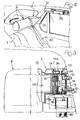
- reference numeral 1 designates the backrest of the rear seat of a car 2 having a compartment 3 with a left side wall 4, a roof 5 and a right side wall (not visible).
- the terms "left” and “right” are used with reference to the direction of movement of the vehicle.
- the left portion of the backrest 1 is provided with a headrest indicated generally by numeral 6.
- the right portion of the backrest is also provided with a headrest identical and symetrical with respect to the headrest 6.
- the headrest 6 is separated from the backrest 1 of the rear seat and, in the case of the illustrated example, is spaced apart from the upper edge of this backrest. Therefore, the headrest according to the invention is not supported by the structure of the seat backrest as in the conventional solutions. It is instead supported on one side thereof in a cantilever fashion by a support element 7 which is fixed to the side wall 4 of the car compartment. More precisely, the headrest 6 is pivotally supported around a vertical axis 8 by the support element 7 and is movable between an operative position of normal use (illustrated with undotted line in the drawings) and an inoperative position, adiacent to the side wall of the compartment, which is illustrated by dotted line in figures 2, 4.
- the support element 7 has a support structure 9 fixed to the car body by screws 10.
- the headrest 6 has, as it is usual, a padding 10 provided with a cover 11, wherein a frame 12 is embedded.
- the frame 12 has a connecting portion 13 arranged outside of the padding 10 and pivotally mounted onto the structure 9 of the support element 7 by interposition of a pivot pin 14.
- the pin 14, for convenience in mounting is comprised of two cap-like elements 14a (figure 3) having an helical spring 15 interposed therebetween and engaging opposite holes 16 formed in the structure 9 of the support element 7.
- the connecting portion 13 of the headrest 6 has a cylindrical surface around which there is wrapped a leaf spring 17 having one end fixed to portion 13 by screws 18 (diagrammatically illustrated in figure 2 by their respective axes) and having the opposite end reacting against the inner ribs 19 of structure 9 (figure 2).
- the leaf spring 17 is bent according to a C shape so that it tends to unbend, pushing the headrest 6 into the inoperative position illustrated by dotted line in figure 2.
- the headrest 6 is held in its operative position, against the action of leaf spring 17, by a locking mechanism including a pair of pawls 20 (figure 2, 3) arranged on a same shaft 21 having end portions 22, 23 which are rotatably and freely supported within cooperating holes formed in the structure 9 of the support element 7.
- a pin spring 25 (figure 2) which tends to keep the pawls 20 in an engagement position within respective seats or notches 24 (figure 2) of the connecting portion 13 of the headrest 6, so as to lock the headrest 6 in its operative position, against the action of the leaf spring 17.
- the end portion 23 of the shaft 21 is connected to an actuating lever 26 arranged above the support element 7 and accessible from the outside.
- the support element 7 is provided at its front portion with a padding 27 with a cooperating cover 28, which define a support surface 29 arranged on the extension of the surface of the headrest 6 and acting as a side cushion, to improve the comfort of the passenger.
- the structure of the support element 7 masks also a guide device and/or a winding device for a safety belt 30 associated with the rear seat.
- the support element 7 allows to fulfil various functions. On the one hand, it fulfills the primary function to support in a cantilever fashion the headrest 6, allowing the latter to be brought rapidly in its inoperative position when one desires to increase visibility during rearward travelling or tilt down the backrest of the rear seat. On the other hand, it fulfills the function of a side cushion, improving thereby the comfort of the passenger.
- the structure 9 of the support element 7 is provided with a slot from which the safety belt is extracted.
- Figure 4 of the drawings shows an alternative embodiment in which the support element 7 is rigidly connected to a further element 31 which supports a handle 32 provided on the side wall of the compartment above the window.
Landscapes
- Engineering & Computer Science (AREA)
- Aviation & Aerospace Engineering (AREA)
- Transportation (AREA)
- Mechanical Engineering (AREA)
- Seats For Vehicles (AREA)
- Chair Legs, Seat Parts, And Backrests (AREA)
Claims (8)
- Kopfstütze für Kraftfahrzeugsitze, insbesondere für Hintersitze, wobei die Kopfstütze (6) von der Rückenlehne (1) des betreffenden Sitzes getrennt ist und an einer Seite desselben schwenkbar durch ein Halteelement (7) gehalten ist, das an einer Wand (4) des Fahrgastraums des Kraftfahrzeugs befestigt ist, welche Kopfstütze (6) zwischen einer Betriebsstellung für normalen Gebrauch und einer Ruhestellung benachbart der Wand (4) des Fahrgastraums beweglich ist, das Halteelement (7) einen Mechanismus (20 bis 26) für die Verriegelung der Kopfstütze (6) in ihrer Betriebsstellung aufweist, dadurch gekennzeichnet, daß der Verriegelungsmechanismus (20 bis 26) eine Welle (21) enthält, die drehbar und frei in dem Aufbau (9) des Halteelements (7) montiert ist, wobei die Welle (21) mit wenigstens einer Klinke (20) zum Zusammenwirken mit einem entsprechenden Sitz (24) des Aufbaus der Kopfstütze (6) versehen ist, um letztere in ihrer Betriebsstellung zu verriegeln, und daß eine Blattfeder (17) wirkungsmäßig zwischen dem Halteelement (7) und dem Kopfstützenaufbau (6) angeordnet ist, die die Kopfstütze (6) in ihre Ruhestellung vorspannt und die am einen Ende am Aufbau der Kopfstütze (6) befestigt ist und sich am entgegengesetzten Ende am Aufbau (9) des Halteelements (7) abstützt.
- Kopfstütze nach Anspruch 1, bei der das Halteelement (7) eine Stützfläche (29) aufweist, die als ein Seitenkissen wirkt und an einem Fortsatz der Oberfläche der Kopfstütze (6) angeordnet ist.
- Kopfstütze nach Anspruch 1, bei der das Halteelement (7) ein Führungselement für einen Sicherheitsgurt (3) aufweist, der dem Kraftfahrzeugsitz zugeordnet ist.
- Kopfstütze nach Anspruch 1, bei der das Halteelement (7) eine Wickelvorrichtung für einen Sicherheitsgurt (30) enthält, der dem Kraftfahrzeugsitz zugeordnet ist.
- Kopfstütze nach Anspruch 1, bei der die Blattfeder (17) in der Betriebsstellung der Kopfstütze (6) eine C-förmige Gestalt aufweist.
- Kopfstütze nach Anspruch 1, bei der die Welle (21) des Verriegelungsmechanismus mit einer Federeinrichtung (25) versehen ist, die dazu neigt, die Klinke (21) in ihrer Eingriffsstellung in dem betreffenden Sitz (24) zu halten, und die starr mit einem von außen zugänglichen Betätigungshebel 26 verbunden ist.
- Kopfstütze nach Anspruch 1, bei der das Halteelement starr mit einem weiteren Element (31) verbunden ist, das an der Seitenwand (4) des Fahrgastraums befestigt ist und einen Handgriff (32) trägt.
- Kopfstütze nach Anspruch 1, bei der die Schwenkachse (8) der Kopfstütze vertikal verläuft.
Applications Claiming Priority (4)
| Application Number | Priority Date | Filing Date | Title |
|---|---|---|---|
| ITTO920825 | 1992-10-14 | ||
| IT92TO825 IT1256969B (it) | 1992-10-14 | 1992-10-14 | Guanciale con poggiatesta incorporato per sedile posteriore di autovettura. |
| ITTO920823 | 1992-10-14 | ||
| IT92TO823 IT1265645B1 (it) | 1992-10-14 | 1992-10-14 | Rotazione laterale del poggiatesta posteriore veicolare. |
Publications (2)
| Publication Number | Publication Date |
|---|---|
| EP0594543A1 EP0594543A1 (de) | 1994-04-27 |
| EP0594543B1 true EP0594543B1 (de) | 1995-05-24 |
Family
ID=26332215
Family Applications (1)
| Application Number | Title | Priority Date | Filing Date |
|---|---|---|---|
| EP93830027A Expired - Lifetime EP0594543B1 (de) | 1992-10-14 | 1993-01-29 | Kopfstütze für Kraftfahrzeugsitze, insbesondere Fondsitze |
Country Status (4)
| Country | Link |
|---|---|
| US (1) | US5346282A (de) |
| EP (1) | EP0594543B1 (de) |
| DE (1) | DE69300163T2 (de) |
| ES (1) | ES2072796T3 (de) |
Families Citing this family (21)
| Publication number | Priority date | Publication date | Assignee | Title |
|---|---|---|---|---|
| US5556171A (en) * | 1995-02-21 | 1996-09-17 | Trw Vehicle Safety Systems Inc. | Seat belt bezel assembly |
| US5590933A (en) * | 1995-03-30 | 1997-01-07 | Lear Seating Corporation | Folding headrest |
| FR2748432B1 (fr) * | 1996-05-13 | 1998-07-24 | Faure Bertrand Equipements Sa | Dispositif d'assise pour vehicule automobile, comportant un appui-tete pivotant escamotable |
| GB2336303A (en) * | 1998-03-04 | 1999-10-20 | Magna Seating Systems Gmbh | Headrest |
| DE19832147A1 (de) * | 1998-07-17 | 2000-01-20 | Cora Stockmann | Kopfstütze für Sitze in Fahrzeugen |
| DE19835355C1 (de) * | 1998-08-05 | 1999-12-02 | Daimler Chrysler Ag | Kopfstütze |
| FR2804915B1 (fr) * | 2000-02-14 | 2002-05-24 | Faure Bertrand Equipements Sa | Siege de vehicule, et vehicule comportant un tel siege |
| US7044554B2 (en) * | 2002-01-29 | 2006-05-16 | Intier Automotive Inc. | Vehicle seat having a head restraint independent from its backrest |
| CA2418563A1 (en) * | 2002-02-11 | 2003-08-11 | Intier Automotive Inc. | Head restraint pivot latch |
| FR2895336B1 (fr) * | 2005-12-22 | 2008-02-15 | Renault Sas | Appui-tete escamotable pour vehicule automobile |
| FR2916423B1 (fr) * | 2007-05-23 | 2010-02-12 | Airbus | Siege avec appui-tete pivotant |
| FR2930208B1 (fr) * | 2008-04-17 | 2010-11-12 | Peugeot Citroen Automobiles Sa | Appuie-tete escamotable. |
| US7651154B1 (en) * | 2008-09-04 | 2010-01-26 | Ford Global Technologies, Llc | One piece modular design for rear seat head restraints and snap in bracket design |
| US8146998B2 (en) * | 2008-09-30 | 2012-04-03 | Lear Corporation | Chuck reducing device |
| GB2469310B (en) * | 2009-04-08 | 2013-11-06 | Ford Global Tech Llc | A seat having an armrest assembly |
| FR2945003B1 (fr) * | 2009-04-30 | 2012-12-21 | Peugeot Citroen Automobiles Sa | Dispositif d'appui-tete lateral pour vehicule |
| FR2955809B1 (fr) * | 2010-02-02 | 2014-11-14 | Peugeot Citroen Automobiles Sa | Dispositif formant appui-tete lateral pour vehicule |
| US8579349B1 (en) * | 2012-01-23 | 2013-11-12 | Phillip E. Schlangen | Headrest assembly |
| US9682781B2 (en) * | 2014-07-22 | 2017-06-20 | Sikorsky Aircraft Corporation | Passive occupant restraint for side-facing aircraft seats |
| US10875435B1 (en) * | 2017-03-30 | 2020-12-29 | Zoox, Inc. | Headrest with passenger flaps |
| DE102019006162B4 (de) * | 2019-09-02 | 2021-11-18 | Grammer Aktiengesellschaft | Betätigungsvorrichtung zur Betätigung einer Ausstattungsvorrichtung des Fahrzeuginnenraums und ein Fahrzeugausstattungsteil |
Family Cites Families (16)
| Publication number | Priority date | Publication date | Assignee | Title |
|---|---|---|---|---|
| US360789A (en) * | 1887-04-05 | James lovell wiseman | ||
| US2649142A (en) * | 1951-10-22 | 1953-08-18 | New Leo | Headrest appliance |
| GB785953A (en) * | 1955-08-03 | 1957-11-06 | Frank Arnau | An improved rest head for vehicles |
| US3310342A (en) * | 1965-01-27 | 1967-03-21 | Drelichowski Kazimierz | Anti-whiplash device |
| US3498671A (en) * | 1968-02-28 | 1970-03-03 | James A Coon | Movable headrest for vehicle seats |
| US3964788A (en) * | 1974-07-03 | 1976-06-22 | Joseph Kmetyko | Headrest for vehicles |
| DE2656249C3 (de) * | 1976-12-11 | 1981-01-08 | Adam Opel Ag, 6090 Ruesselsheim | Aufprallschutzvorrichtung für die Insassen von Fahrzeugen, insbesondere von Personenkraftfahrzeugen |
| US4113310A (en) * | 1977-12-21 | 1978-09-12 | General Motors Corporation | Headrest for vehicles |
| DE2757188A1 (de) * | 1977-12-22 | 1979-06-28 | Carl Maria Best | Kopfstuetze |
| FR2421080A1 (fr) * | 1978-03-31 | 1979-10-26 | Peugeot | Agencement d'un appui-tete dans un vehicule automobile |
| DE3506074A1 (de) * | 1985-02-21 | 1986-08-21 | Karl 8022 Grünwald Gercken | Schwenkbare kopfstuetze fuer eine ruecksitzanordnung |
| US4725076A (en) * | 1986-08-25 | 1988-02-16 | General Motors Corporation | Occupant restraining head rest and seat belt |
| DE3821366C1 (en) * | 1988-06-24 | 1989-07-13 | Daimler-Benz Aktiengesellschaft, 7000 Stuttgart, De | Head-restraint arrangement for the rear seat of a vehicle |
| US4907835A (en) * | 1988-08-08 | 1990-03-13 | Charles Salters | Portable arm rest apparatus |
| US4881777A (en) * | 1988-08-22 | 1989-11-21 | General Motors Corporation | Apparatus and method of utilization thereof of a profile headrest |
| DE9102217U1 (de) * | 1991-02-25 | 1991-07-04 | Autoliv Development AB, Vårgårda | Rückhaltesystem |
-
1993
- 1993-01-29 ES ES93830027T patent/ES2072796T3/es not_active Expired - Lifetime
- 1993-01-29 DE DE69300163T patent/DE69300163T2/de not_active Expired - Fee Related
- 1993-01-29 EP EP93830027A patent/EP0594543B1/de not_active Expired - Lifetime
- 1993-03-09 US US08/029,051 patent/US5346282A/en not_active Expired - Fee Related
Also Published As
| Publication number | Publication date |
|---|---|
| DE69300163D1 (de) | 1995-06-29 |
| US5346282A (en) | 1994-09-13 |
| EP0594543A1 (de) | 1994-04-27 |
| DE69300163T2 (de) | 1996-01-25 |
| ES2072796T3 (es) | 1995-07-16 |
Similar Documents
| Publication | Publication Date | Title |
|---|---|---|
| EP0594543B1 (de) | Kopfstütze für Kraftfahrzeugsitze, insbesondere Fondsitze | |
| EP0604375B1 (de) | Armstütze für Hintersitze von Kraftfahrzeuge | |
| US4626028A (en) | Seat for vehicles | |
| US5265937A (en) | Seat back inertia lock | |
| EP1206367B1 (de) | Klappbare u-förmige kopfstütze | |
| EP1888367B1 (de) | Umwandelbarer monogestellsitz | |
| US5460429A (en) | Inertia latch assembly for seat hinge mechanism | |
| US6663180B2 (en) | Vehicle seat provided with a fold-down back | |
| US4579387A (en) | Motor vehicle seat hinge | |
| US4169626A (en) | Reclining vehicle seat | |
| US4639037A (en) | Auxiliary seat assembly for use in vehicles | |
| US4286819A (en) | Rear seat for cars | |
| JPH09301031A (ja) | 乗物シートに取付けるロック機構およびその機構を取付けた乗物シート | |
| WO2003106214A1 (en) | Seat assembly with integral head/neck rest | |
| US5673972A (en) | Vehicle seat assembly | |
| US5873633A (en) | Retardation lock member for motor vehicle seat component | |
| US20030006641A1 (en) | Device for the detachable attachment of an object, in particular a child's safety seat, on a motor vehicle seat | |
| EP0965488B1 (de) | Vorrichtung zur Ermöglichung des Durchlasses zwischen Sitz- u. Kofferraum eines Kraftfahrzeuges | |
| JP2003127741A (ja) | 車両用シート構造 | |
| EP0713800B1 (de) | Kraftfahrzeugrücksitz | |
| GB2080673A (en) | Seat belts | |
| EP0422527B1 (de) | Vorrichtung zum Umklappen einer Rückenlehne eines Fahrzeugsitzes, insbesondere eines Rücksitzes eines Kraftfahrzeuges | |
| EP0068322B1 (de) | Passives Sicherheitsgurt-System für ein Kraftfahrzeug mit kippbaren Sitzen | |
| EP0925994A1 (de) | Kopfstütze für Kraftfahrzeugsitze | |
| KR0119895B1 (ko) | 자동차용 섭동식 시트의 레버장치 |
Legal Events
| Date | Code | Title | Description |
|---|---|---|---|
| PUAI | Public reference made under article 153(3) epc to a published international application that has entered the european phase |
Free format text: ORIGINAL CODE: 0009012 |
|
| AK | Designated contracting states |
Kind code of ref document: A1 Designated state(s): DE ES FR GB SE |
|
| 17P | Request for examination filed |
Effective date: 19940812 |
|
| 17Q | First examination report despatched |
Effective date: 19941102 |
|
| GRAA | (expected) grant |
Free format text: ORIGINAL CODE: 0009210 |
|
| AK | Designated contracting states |
Kind code of ref document: B1 Designated state(s): DE ES FR GB SE |
|
| REF | Corresponds to: |
Ref document number: 69300163 Country of ref document: DE Date of ref document: 19950629 |
|
| REG | Reference to a national code |
Ref country code: ES Ref legal event code: FG2A Ref document number: 2072796 Country of ref document: ES Kind code of ref document: T3 |
|
| ET | Fr: translation filed | ||
| PLBE | No opposition filed within time limit |
Free format text: ORIGINAL CODE: 0009261 |
|
| STAA | Information on the status of an ep patent application or granted ep patent |
Free format text: STATUS: NO OPPOSITION FILED WITHIN TIME LIMIT |
|
| 26N | No opposition filed | ||
| REG | Reference to a national code |
Ref country code: GB Ref legal event code: IF02 |
|
| PGFP | Annual fee paid to national office [announced via postgrant information from national office to epo] |
Ref country code: SE Payment date: 20030117 Year of fee payment: 11 Ref country code: FR Payment date: 20030117 Year of fee payment: 11 |
|
| PGFP | Annual fee paid to national office [announced via postgrant information from national office to epo] |
Ref country code: ES Payment date: 20030120 Year of fee payment: 11 |
|
| PGFP | Annual fee paid to national office [announced via postgrant information from national office to epo] |
Ref country code: GB Payment date: 20030213 Year of fee payment: 11 |
|
| PGFP | Annual fee paid to national office [announced via postgrant information from national office to epo] |
Ref country code: DE Payment date: 20030227 Year of fee payment: 11 |
|
| PG25 | Lapsed in a contracting state [announced via postgrant information from national office to epo] |
Ref country code: GB Free format text: LAPSE BECAUSE OF NON-PAYMENT OF DUE FEES Effective date: 20040129 |
|
| PG25 | Lapsed in a contracting state [announced via postgrant information from national office to epo] |
Ref country code: SE Free format text: LAPSE BECAUSE OF NON-PAYMENT OF DUE FEES Effective date: 20040130 Ref country code: ES Free format text: LAPSE BECAUSE OF NON-PAYMENT OF DUE FEES Effective date: 20040130 |
|
| PG25 | Lapsed in a contracting state [announced via postgrant information from national office to epo] |
Ref country code: DE Free format text: LAPSE BECAUSE OF NON-PAYMENT OF DUE FEES Effective date: 20040803 |
|
| EUG | Se: european patent has lapsed | ||
| GBPC | Gb: european patent ceased through non-payment of renewal fee |
Effective date: 20040129 |
|
| PG25 | Lapsed in a contracting state [announced via postgrant information from national office to epo] |
Ref country code: FR Free format text: LAPSE BECAUSE OF NON-PAYMENT OF DUE FEES Effective date: 20040930 |
|
| REG | Reference to a national code |
Ref country code: FR Ref legal event code: ST |
|
| REG | Reference to a national code |
Ref country code: ES Ref legal event code: FD2A Effective date: 20040130 |