EP0594548B1 - Dispositif pour circulation automatique dans une station de pompage des eaux usées - Google Patents
Dispositif pour circulation automatique dans une station de pompage des eaux usées Download PDFInfo
- Publication number
- EP0594548B1 EP0594548B1 EP93850173A EP93850173A EP0594548B1 EP 0594548 B1 EP0594548 B1 EP 0594548B1 EP 93850173 A EP93850173 A EP 93850173A EP 93850173 A EP93850173 A EP 93850173A EP 0594548 B1 EP0594548 B1 EP 0594548B1
- Authority
- EP
- European Patent Office
- Prior art keywords
- valve
- chamber
- pump
- pressure
- circulation
- Prior art date
- Legal status (The legal status is an assumption and is not a legal conclusion. Google has not performed a legal analysis and makes no representation as to the accuracy of the status listed.)
- Expired - Lifetime
Links
- 238000005086 pumping Methods 0.000 title claims description 11
- 239000002351 wastewater Substances 0.000 title 1
- 239000012528 membrane Substances 0.000 claims description 8
- 239000010865 sewage Substances 0.000 claims description 3
- XLYOFNOQVPJJNP-UHFFFAOYSA-N water Substances O XLYOFNOQVPJJNP-UHFFFAOYSA-N 0.000 claims 1
- 239000010802 sludge Substances 0.000 description 4
- 239000004575 stone Substances 0.000 description 2
- 238000013019 agitation Methods 0.000 description 1
- 239000011324 bead Substances 0.000 description 1
- 238000005260 corrosion Methods 0.000 description 1
- 230000007797 corrosion Effects 0.000 description 1
- 238000004880 explosion Methods 0.000 description 1
- 239000002360 explosive Substances 0.000 description 1
- 239000012530 fluid Substances 0.000 description 1
- 238000011010 flushing procedure Methods 0.000 description 1
- 238000009434 installation Methods 0.000 description 1
- 238000000034 method Methods 0.000 description 1
- 238000005192 partition Methods 0.000 description 1
- 238000007789 sealing Methods 0.000 description 1
- 239000007787 solid Substances 0.000 description 1
Images
Classifications
-
- E—FIXED CONSTRUCTIONS
- E03—WATER SUPPLY; SEWERAGE
- E03F—SEWERS; CESSPOOLS
- E03F5/00—Sewerage structures
- E03F5/22—Adaptations of pumping plants for lifting sewage
-
- F—MECHANICAL ENGINEERING; LIGHTING; HEATING; WEAPONS; BLASTING
- F04—POSITIVE - DISPLACEMENT MACHINES FOR LIQUIDS; PUMPS FOR LIQUIDS OR ELASTIC FLUIDS
- F04D—NON-POSITIVE-DISPLACEMENT PUMPS
- F04D15/00—Control, e.g. regulation, of pumps, pumping installations or systems
- F04D15/0005—Control, e.g. regulation, of pumps, pumping installations or systems by using valves
- F04D15/0011—Control, e.g. regulation, of pumps, pumping installations or systems by using valves by-pass valves
Definitions
- the invention concerns a device for providing circulation in pumping stations which are parts of a municipal sewage system.
- Sludge banks occur in pumping stations and other tanks in a sewage system as the circulation is not good enough. Sludge banks mean a lot of problems such as a bad smell, risk for explosions, corrosion problems etc.
- the problems have been solved by arranging a valve in the pump outlet, which is opened temporarily thus obtaining a circulation and flushing in the pumping station.
- the sludge banks are dissolved and the fluid is homogenized.
- the purpose of this invention is to obtain a device which in a simple and reliable way controls the valve and which is less sensitive to clogging. This is obtained by help of the method and the device stated in the claims.
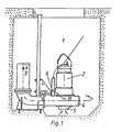
- Fig 1 shows a pumping station with a pump unit and attached valve.
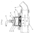
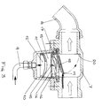
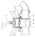
- Figs 2 to 4 show the principle design of the valve in different operating positions.
- FIG. 1 stands for a pumping station with a submersible pump unit 2 connected to a pressure pipe 3.
- 4 stands for the pump housing having an inlet 5
- 6 stands for a mixing valve mounted on the pump housing 4.
- 7 stands for a cylindric part of the valve 6 and 8 its outlet.
- 9 stands for a pressure connection from the pump housing 4, 10 a membrane housing with a membrane 11 which parts two chambers 12 and 13.
- 14 stands for a partition wall having an opening 15, 16 an additional chamber, 17 a flexible wall, 18 a valve flap having a leading edge and 20 finally a valve seat.
- the device operates in the following manner: Normally the valve 6 is closed and the pumped medium is transported from the pump housing 4 and into the pressure pipe 3. The flow direction is shown by the Arrow A.
- valve is open, which means that a certain amount of the pumped medium flows through the valve, arrow B, and obtains a strong agitation in the pump station wrenching possible sludge banks. After a certain time, the valve is closed and the pumping takes place in the normal way.
- the valve 6 comprises a cylindric part 7 and an outlet 8.
- a pressure pipe 9 from the pump housing 4 is connected to the cylindric part 7 via a membrane housing 10 having a first chamber 12.
- the pressure therein acts upon a membrane 11 which in its turn influences on the pressure in another chamber 13 containing a dampening medium such as oil.
- the chamber 13 is further limited by a wall 14 provided with a narrow opening 15 creating a connection with a second oil chamber 16.
- the latter has a flexible wall 17 arranged to be able to act upon a valve flap 18 for a temporary closing of the valve 6.
- Fig 2 shows the valve in an open position which means that circulation is taking place in the pumping station.
- the valve flap 18 then takes a position entirely beside the flow. This is the situation at pump start.
- the pressure in the pump outlet thus acts upon the flap 18 via the chamber 12, the membrane 11 the chamber 13 the opening 15 and the chamber 16.
- the time before which the flap is being closed may be decided by dimensioning the opening 15. The smaller opening, the longer time before enough oil has flown into the chamber 16 to obtain a sufficient force onto the flap 18.
- the suitable opening time may vary depending on the type of pump station and is preferably possible to adjust from outside.
Landscapes
- Engineering & Computer Science (AREA)
- Health & Medical Sciences (AREA)
- Life Sciences & Earth Sciences (AREA)
- Hydrology & Water Resources (AREA)
- Public Health (AREA)
- Water Supply & Treatment (AREA)
- Mechanical Engineering (AREA)
- General Engineering & Computer Science (AREA)
- Structures Of Non-Positive Displacement Pumps (AREA)
- Reciprocating Pumps (AREA)
Claims (3)
- Dispositif pour fournir une circulation automatique dans des stations de pompage d'eau d'égout contenant une ou plusieurs unités de pompe, de préférence des pompes centrifuges du type submersible, dont une ou plusieurs sont munies de vannes de mélange, qui automatiquement, pendant une certaine période ou des périodes de temps limitées, relient le côté de refoulement d'une pompe avec une station de pompage (1) obtenant ainsi une circulation du milieu pompé, et dans lequel la connexion de retour alternée à la station de pompage (1) s'effectue via une vanne (6) comprenant un boîtier (10) relié au côté de refoulement de la pompe par un tuyau (9), caractérisé en ce qu'il comprend un boîtier (10) qui est relié à une pièce (7) de la vanne (6) en forme de cylindre et contient une membrane (11), dont un côté est actionné par la pression dans le boîtier (4) de pompe, pendant que son autre côté constitue une paroi d'une chambre (13) contenant un milieu d'amortissement tel que de l'huile, et un volet (18) chargé par un ressort qui est monté dans la pièce (7) de la vanne en forme de cylindre et qui est agencé pour être capable de fermer ladite vanne et interrompre la circulation, le volet de vanne (18) étant agencé pour être directement ou indirectement déplacé contre la force de ressort, dans un sens de fermeture par la pression dans la chambre (13) commandée par la membrane (11).
- Dispositif selon la revendication 1,
caractérisé en ce que la chambre (13), est reliée, via une ouverture (15), à une autre chambre (16) qui a une paroi flexible (17) agencée pour être capable d'actionner le volet (18) de vanne dans un sens de fermeture. - Dispositif selon la revendication 2,
caractérisé en ce que l'ouverture (15) est réglable pour commander la durée pendant laquelle la pression dans la chambre (16) est suffisamment importante pour faire basculer le volet (18) de vanne dans le flux à travers la vanne (6) et interrompre la circulation.
Applications Claiming Priority (2)
| Application Number | Priority Date | Filing Date | Title |
|---|---|---|---|
| SE9202759A SE469844B (sv) | 1992-09-24 | 1992-09-24 | Anordning för att åstadkomma cirkulation i pumpstationer |
| SE9202759 | 1992-09-24 |
Publications (2)
| Publication Number | Publication Date |
|---|---|
| EP0594548A1 EP0594548A1 (fr) | 1994-04-27 |
| EP0594548B1 true EP0594548B1 (fr) | 1997-08-13 |
Family
ID=20387260
Family Applications (1)
| Application Number | Title | Priority Date | Filing Date |
|---|---|---|---|
| EP93850173A Expired - Lifetime EP0594548B1 (fr) | 1992-09-24 | 1993-09-08 | Dispositif pour circulation automatique dans une station de pompage des eaux usées |
Country Status (3)
| Country | Link |
|---|---|
| EP (1) | EP0594548B1 (fr) |
| DE (1) | DE69313069T2 (fr) |
| SE (1) | SE469844B (fr) |
Families Citing this family (3)
| Publication number | Priority date | Publication date | Assignee | Title |
|---|---|---|---|---|
| DE4415233C1 (de) * | 1994-04-30 | 1995-12-14 | Abs Pumps Ltd | Spülventil |
| IT1314629B1 (it) * | 2000-05-12 | 2002-12-20 | Zenit Spa | Valvola di flussaggio |
| CN107288921A (zh) * | 2017-08-08 | 2017-10-24 | 苏州克莱尔环保科技有限公司 | 搅碎式提升泵站 |
-
1992
- 1992-09-24 SE SE9202759A patent/SE469844B/sv not_active IP Right Cessation
-
1993
- 1993-09-08 DE DE1993613069 patent/DE69313069T2/de not_active Expired - Fee Related
- 1993-09-08 EP EP93850173A patent/EP0594548B1/fr not_active Expired - Lifetime
Non-Patent Citations (3)
| Title |
|---|
| EP-A- 0 058 648 * |
| EP-A- 0 384 903 * |
| EP-A- 0 472 509 * |
Also Published As
| Publication number | Publication date |
|---|---|
| EP0594548A1 (fr) | 1994-04-27 |
| SE9202759D0 (sv) | 1992-09-24 |
| SE9202759L (sv) | 1993-09-27 |
| SE469844B (sv) | 1993-09-27 |
| DE69313069T2 (de) | 1998-02-19 |
| DE69313069D1 (de) | 1997-09-18 |
Similar Documents
| Publication | Publication Date | Title |
|---|---|---|
| CA2009906C (fr) | Methode et dispositif de circulation automatique dans les postes de pompage des eaux usees | |
| EP0472509B1 (fr) | Procédé et dispositif pour la circulation automatique dans une station de pompage d'eaux usées | |
| US5660533A (en) | Vacuum assisted priming and cooling system for a pump | |
| EP0359730B1 (fr) | Dispositif pour la circulation automatique dans une station de pompage d'eaux usées | |
| EP0623713B1 (fr) | Procédé et dispositif pour la circulation automatique dans une station de pompage d'eau usée | |
| EP0594548B1 (fr) | Dispositif pour circulation automatique dans une station de pompage des eaux usées | |
| US5302088A (en) | Water powered sump pump | |
| JP3363362B2 (ja) | 逆流防止装置を備えた水中ポンプユニット | |
| EP0058648B1 (fr) | Dispositif par circulation automatique dans une station de pompage des eaux usées | |
| US5601111A (en) | Method for automatically circulating and then halting circulation of wastewater in a wastewater pump station, and a valving device therefore | |
| US1774234A (en) | Sewage ejector | |
| JP3007791B2 (ja) | 液状物等流体の自動移送装置 | |
| KR200194147Y1 (ko) | 펌프시스템 | |
| JP2869696B2 (ja) | 真空式下水収集システムの空気取込装置 | |
| SU747950A1 (ru) | Установка дл перекачки сточных вод | |
| KR100343437B1 (ko) | 고형물 혼입 액체용 펌프 및 펌프시스템 | |
| JP3025922U (ja) | 間欠圧送式汚水排出装置 | |
| GB2268889A (en) | Mixing wastewater in a sewage pumping station | |
| JPH0762720A (ja) | 下水ポンプシステム | |
| KR19990027186A (ko) | 에어 밸브 |
Legal Events
| Date | Code | Title | Description |
|---|---|---|---|
| PUAI | Public reference made under article 153(3) epc to a published international application that has entered the european phase |
Free format text: ORIGINAL CODE: 0009012 |
|
| AK | Designated contracting states |
Kind code of ref document: A1 Designated state(s): DE FR GB IT NL |
|
| 17P | Request for examination filed |
Effective date: 19941017 |
|
| GRAG | Despatch of communication of intention to grant |
Free format text: ORIGINAL CODE: EPIDOS AGRA |
|
| 17Q | First examination report despatched |
Effective date: 19961203 |
|
| GRAH | Despatch of communication of intention to grant a patent |
Free format text: ORIGINAL CODE: EPIDOS IGRA |
|
| GRAH | Despatch of communication of intention to grant a patent |
Free format text: ORIGINAL CODE: EPIDOS IGRA |
|
| GRAA | (expected) grant |
Free format text: ORIGINAL CODE: 0009210 |
|
| AK | Designated contracting states |
Kind code of ref document: B1 Designated state(s): DE FR GB IT NL |
|
| REF | Corresponds to: |
Ref document number: 69313069 Country of ref document: DE Date of ref document: 19970918 |
|
| ET | Fr: translation filed | ||
| PLBE | No opposition filed within time limit |
Free format text: ORIGINAL CODE: 0009261 |
|
| STAA | Information on the status of an ep patent application or granted ep patent |
Free format text: STATUS: NO OPPOSITION FILED WITHIN TIME LIMIT |
|
| 26N | No opposition filed | ||
| REG | Reference to a national code |
Ref country code: GB Ref legal event code: IF02 |
|
| PGFP | Annual fee paid to national office [announced via postgrant information from national office to epo] |
Ref country code: GB Payment date: 20020904 Year of fee payment: 10 |
|
| PGFP | Annual fee paid to national office [announced via postgrant information from national office to epo] |
Ref country code: FR Payment date: 20020910 Year of fee payment: 10 |
|
| PGFP | Annual fee paid to national office [announced via postgrant information from national office to epo] |
Ref country code: DE Payment date: 20020911 Year of fee payment: 10 |
|
| PGFP | Annual fee paid to national office [announced via postgrant information from national office to epo] |
Ref country code: NL Payment date: 20020930 Year of fee payment: 10 |
|
| PG25 | Lapsed in a contracting state [announced via postgrant information from national office to epo] |
Ref country code: GB Free format text: LAPSE BECAUSE OF NON-PAYMENT OF DUE FEES Effective date: 20030908 |
|
| PG25 | Lapsed in a contracting state [announced via postgrant information from national office to epo] |
Ref country code: NL Free format text: LAPSE BECAUSE OF NON-PAYMENT OF DUE FEES Effective date: 20040401 Ref country code: DE Free format text: LAPSE BECAUSE OF NON-PAYMENT OF DUE FEES Effective date: 20040401 |
|
| GBPC | Gb: european patent ceased through non-payment of renewal fee |
Effective date: 20030908 |
|
| PG25 | Lapsed in a contracting state [announced via postgrant information from national office to epo] |
Ref country code: FR Free format text: LAPSE BECAUSE OF NON-PAYMENT OF DUE FEES Effective date: 20040528 |
|
| NLV4 | Nl: lapsed or anulled due to non-payment of the annual fee |
Effective date: 20040401 |
|
| REG | Reference to a national code |
Ref country code: FR Ref legal event code: ST |
|
| PG25 | Lapsed in a contracting state [announced via postgrant information from national office to epo] |
Ref country code: IT Free format text: LAPSE BECAUSE OF NON-PAYMENT OF DUE FEES;WARNING: LAPSES OF ITALIAN PATENTS WITH EFFECTIVE DATE BEFORE 2007 MAY HAVE OCCURRED AT ANY TIME BEFORE 2007. THE CORRECT EFFECTIVE DATE MAY BE DIFFERENT FROM THE ONE RECORDED. Effective date: 20050908 |