EP0594730B1 - Modularer sichter - Google Patents
Modularer sichter Download PDFInfo
- Publication number
- EP0594730B1 EP0594730B1 EP92915533A EP92915533A EP0594730B1 EP 0594730 B1 EP0594730 B1 EP 0594730B1 EP 92915533 A EP92915533 A EP 92915533A EP 92915533 A EP92915533 A EP 92915533A EP 0594730 B1 EP0594730 B1 EP 0594730B1
- Authority
- EP
- European Patent Office
- Prior art keywords
- separator
- chamber
- conveyor
- separation
- air
- Prior art date
- Legal status (The legal status is an assumption and is not a legal conclusion. Google has not performed a legal analysis and makes no representation as to the accuracy of the status listed.)
- Expired - Lifetime
Links
- 241000208125 Nicotiana Species 0.000 claims abstract description 73
- 235000002637 Nicotiana tabacum Nutrition 0.000 claims abstract description 73
- 230000002441 reversible effect Effects 0.000 claims abstract description 8
- 238000000926 separation method Methods 0.000 claims description 40
- 239000000463 material Substances 0.000 claims description 32
- 238000011144 upstream manufacturing Methods 0.000 claims description 17
- 239000000203 mixture Substances 0.000 claims description 7
- 238000000034 method Methods 0.000 claims description 4
- 230000000630 rising effect Effects 0.000 claims description 2
- 238000007664 blowing Methods 0.000 claims 3
- 230000001419 dependent effect Effects 0.000 claims 3
- 238000012216 screening Methods 0.000 claims 1
- 239000000428 dust Substances 0.000 abstract description 6
- 239000002245 particle Substances 0.000 abstract description 3
- 239000000725 suspension Substances 0.000 abstract description 2
- 238000004140 cleaning Methods 0.000 description 9
- 241000251169 Alopias vulpinus Species 0.000 description 7
- 238000012423 maintenance Methods 0.000 description 6
- 238000007599 discharging Methods 0.000 description 5
- 239000000543 intermediate Substances 0.000 description 5
- 239000002184 metal Substances 0.000 description 5
- 238000010276 construction Methods 0.000 description 3
- 238000007689 inspection Methods 0.000 description 2
- 238000009434 installation Methods 0.000 description 2
- 230000007246 mechanism Effects 0.000 description 2
- 241000196324 Embryophyta Species 0.000 description 1
- 241000555745 Sciuridae Species 0.000 description 1
- 238000005266 casting Methods 0.000 description 1
- 230000002354 daily effect Effects 0.000 description 1
- 230000003203 everyday effect Effects 0.000 description 1
- 230000003134 recirculating effect Effects 0.000 description 1
- 230000000717 retained effect Effects 0.000 description 1
- 235000019505 tobacco product Nutrition 0.000 description 1
Images


Classifications
-
- A—HUMAN NECESSITIES
- A24—TOBACCO; CIGARS; CIGARETTES; SIMULATED SMOKING DEVICES; SMOKERS' REQUISITES
- A24B—MANUFACTURE OR PREPARATION OF TOBACCO FOR SMOKING OR CHEWING; TOBACCO; SNUFF
- A24B5/00—Stripping tobacco; Treatment of stems or ribs
- A24B5/10—Stripping tobacco; Treatment of stems or ribs by crushing the leaves with subsequent separating
-
- B—PERFORMING OPERATIONS; TRANSPORTING
- B07—SEPARATING SOLIDS FROM SOLIDS; SORTING
- B07B—SEPARATING SOLIDS FROM SOLIDS BY SIEVING, SCREENING, SIFTING OR BY USING GAS CURRENTS; SEPARATING BY OTHER DRY METHODS APPLICABLE TO BULK MATERIAL, e.g. LOOSE ARTICLES FIT TO BE HANDLED LIKE BULK MATERIAL
- B07B4/00—Separating solids from solids by subjecting their mixture to gas currents
- B07B4/02—Separating solids from solids by subjecting their mixture to gas currents while the mixtures fall
- B07B4/025—Separating solids from solids by subjecting their mixture to gas currents while the mixtures fall the material being slingered or fled out horizontally before falling, e.g. by dispersing elements
-
- B—PERFORMING OPERATIONS; TRANSPORTING
- B07—SEPARATING SOLIDS FROM SOLIDS; SORTING
- B07B—SEPARATING SOLIDS FROM SOLIDS BY SIEVING, SCREENING, SIFTING OR BY USING GAS CURRENTS; SEPARATING BY OTHER DRY METHODS APPLICABLE TO BULK MATERIAL, e.g. LOOSE ARTICLES FIT TO BE HANDLED LIKE BULK MATERIAL
- B07B9/00—Combinations of apparatus for screening or sifting or for separating solids from solids using gas currents; General arrangement of plant, e.g. flow sheets
- B07B9/02—Combinations of similar or different apparatus for separating solids from solids using gas currents
Definitions
- This invention relates to classifiers and more particularly to the separation of lighter tobacco fractions from heavier tobacco fractions in a mix of threshed tobacco.
- threshers are used to remove tobacco leaf or lamina from the stem portions of the plant.
- the mixed stem and leaf fractions are discharged from the thresher in a mixed stream of tobacco material.
- This stream is then typically conveyed to a classifier or separator where the lighter fractions such as lamina, are separated from the heavier fractions, such as stem or stem with leaf attached.
- a classifier or separator is disclosed, for example, in U.S. Patent No. 4,915,824.
- a further objective of the invention has been to provide self-cleaning modular classifier apparatus.
- a further objective of the invention has been to provide a classifying module and infeed apparatus which can be combined or interchanged with other modules and infeeds for classifying light fractions from heavier fractions in a mix thereof introduced to each module.
- Apparatus for separating heavy and light material fractions, such as tobacco stem and tobacco lamina, conveyed in a mixed stream of such material comprises a separator having an upper separation chamber, infeed means operably associated with the separator having means for projecting a mixed stream into the upper separation chamber of the separator across a rising flow of air so that lighter fractions are removed upwardly while heavier fractions fall out for disposal, and conveyor means for receiving heavier fractions falling out of the mixed stream, characterised in that the apparatus comprises a plurality of such classifying separators, in that the conveyor means extends through each separator for conveying the heavier fractions through successive downstream separators, in that each separator, except for the last downstream separator, has means for receiving remaining fractions in the stream not carried upwardly or falling out, and for delivering such remaining fractions to the projecting means of a downstream separator and in that the separators, except for the last downstream separator, are interchangeable such that the apparatus may be formed with the separators in any order.
- the plurality of operationally linked single pass, vertical lift separators are in modular form and are each fed by an infeed means discharging certain of the heavier fractions across the module directly into the infeed means of the next downstream module.
- the infeed means of each module projects mixed tobacco fed to it across a classifying chamber defined in each module, where lighter fractions are lifted and separated from heavier fractions by means of a vertically upward moving portion of a closed air loop.
- Each module has a heavy fraction removal chamber adapted for interconnection to like chambers of adjacent nodules on either side of the module.
- a common porous conveyor apron extends through such interconnected chambers to convey heavies to a single discharge point.
- Each module has an air inlet plenum beneath the porous apron for receiving air from a blower and directing it upwardly through the apron for separating light fractions from heavier fractions cast across the classifying chamber.
- a reversible common second conveyor extends beneath each module in the air inlet plenums for catching and conveying dust or other material falling from the porous apron and out of the air stream. When operated in one direction, the second conveyor discharges material thereon back into the heavies emanating from the linked modules. When operating in another direction, the second conveyor discharges material thereon to a different discharge point for removal, processing or disposal.
- the infeed apparatus for each module receives incoming tobacco material directly from the initial feed duct or from the next upstream module, and projects a stream of material across its own classifying chamber directly toward the inlet of the next module's infeed apparatus.
- the infeeds may be of a variety of types, such as belt, rotor or winnower and each infeed, regardless of type, is preferably constructed so it is interchangeable with any other infeed.
- Each module in the chain thus has three different effluents, lights, mixed tobacco projected into the infeed of the next downstream module, and heavies, such as stems with no attached lamina.
- Any number of modules can be linked together depending on the classification results desired, and it is not necessary to provide separate conveying apparatus to convey the mixed effluent from one module to the next. Should any infeed apparatus break down, or should another type infeed be desired, it is only necessary to unbolt the infeed in place and insert the desired unit.
- the invention provides a truly modular, self-cleaning classifier having the capacity to save large amounts of energy required by systems where separate conveying apparatus is required between each separator.
- Fig. 1 there is shown therein a modular classifier apparatus 10. While there may be other applications for such apparatus one particular application which the apparatus depicted in Fig. 1 has found particularly utility is in the classification of tobacco.
- the tobacco Upon discharge from the threshing machine, the tobacco constitutes a plurality of different forms. It includes free lamina, lamina attached to stem, and clean stem.
- the free lamina are generally considered to be a light fraction of the mixture emanating from the thresher, while the stems are generally considered to be a heavy fraction.
- the lamina attached to the stems are also heavies or intermediates.
- the modular classifying apparatus includes a plurality of vertical lift, single pass separators 11, 12, 13, 14. Each separator is similar in construction, except as noted below. Each is connected to another for receiving a mixture of tobacco, casting it across a classification chamber, collecting lights lifted away from the projected tobacco stream, and collecting heavies and other components for further treatment or separation.
- Separator 13 is similar to all of the other separators as will be appreciated. It includes a sheet metal housing 16 defining a separation or classification chamber 17. Chamber 17 has an upper tapering hood 18 defining a light fraction removal chamber and feeding into a rotary screen air separator 19.
- Rotary screen air separator 19 includes a rotating screen 20 disposed for rotation about an axis 21. As tobacco moves through the inlet port 22 and toward the screen 20, it generally engages a back wall 23 where it falls and drops toward air lock 24.
- Air lock 24 has an inlet 25, and a plurality of rotating blades 26 which wipe and seal against the cylindrical walls 27. As the blades 26 rotate, they move tobacco entering the inlet 25 into a discharge chute 28 where the light fraction tobacco is dropped onto a conveyor belt 29, for example, for transport for further processing.
- Fig. 4 the separator 14 is shown just to the right of the separator 13 for orientation purposes. Also, a port 30 is provided in the hood 18 of each separator and a light of any suitable construction (not shown) is mounted therein so that the internal operation can be viewed through transparent door 43.
- the separator 13 has an intermediate portion in which is located the classification chamber 17. Separator 13 also has an opening 34 and an opening 35 defined by the respective flanges 36, 37. Openings 34, 35 constitute essentially rectangularly shaped openings in the separator 13. These openings are filled by cooperating infeed means as will be described to further define walls of the chamber 17.
- Housing 16 is also provided with an access door 43 which may be clear for viewing, but in any event provides access into the chamber 17 for any necessary maintenance or inspection.
- each separator such as separator 13 is provided with a rectangularly shaped, heavies removal chamber 45.
- Rectangular chamber 45 is of relatively low height as shown in Fig. 3, but wide enough to extend across and beyond the separation chamber 17 (as indicated in Fig. 2).
- Chamber 45 openly communicates with chamber 17 above, and with an air plenum below, as will be described.
- Flanges 46, 47 are provided at an upstream end of the heavies removal chamber 45 and flanges 48, 49 are provided at the downstream end of the heavies removal chamber 45 for the purpose of securing this chamber to respective chambers 45 of upstream classifier 12 and the downstream classifier 14.
- the chambers 45 are provided with access doors such as at 54 for maintenance or inspection.
- a heavies collection conveyor 58 comprising a porous apron or belt so that air can pass through it, extends through the various chambers 45 when the classifiers are connected together.
- each of the modular classifiers is provided with an infeed apparatus such as shown at 60, 61, 62, 63.
- These infeed apparatus are operable to receive tobacco and to project tobacco across the classification chamber 17 of the respective classifiers so that air moving upwardly through the porous conveyor 58 can carry the lights upwardly into the hoods 18, while other tobacco is projected into the inlets of the next downstream feed means.
- some tobacco projected by infeed means 60 is carried upwardly into hood 18 of classifier 11 and some of the tobacco is directed into the inlet 64 of infeed means 61 where that tobacco is then projected across the separation chamber 17 of classifier 12, and so on.
- infeed means 60, 61, 62 all comprise multiple vaned rotors.
- Infeed means 63 comprises a belt conveyor. These various infeed means are interchangeable whether a rotor is used or a belt infeed 63 is used. Alternately, a winnower infeed means having fingers or rakes rotating clockwise as seen in Fig. 1, could be used to engage incoming tobacco and project it across chambers 17. All these respective infeed means are so constructed that they can be interchanged one for the other as is desirable.
- Infeed means 62 comprising a variable speed rotor infeed is operably interconnected between separators 12 and 13.
- This infeed means comprises a multiple vaned rotor driven by a belt or chain 65 which is in turn driven by an electric motor 66 attached to the housing 16 of the classifier 13.
- Infeed means 62 comprises a sheet metal housing supporting the rotor axis 67 and defining an inlet 68 and outlet 69. Tobacco from separator 12 is projected into inlet 68 and counterclockwise rotation of the rotor then projects tobacco through the outlet 69 into the classification chamber 17 of separator 13.
- the infeed means is further provided with external flanges 72, 73 for interconnection with the flanges 37, 36, respectively, of the two adjacent separators 12 and 13.
- the infeed means 62 also comprises a plurality of sheet metal walls, such as at 74 and 75, for example. These walls actually define, when the infeed means is in place with respect to separator 12, walls of the classification chamber 17 thereof.
- the inlet 68 is defined in part by the top edge of the wall 74 and the wall 75, for example.
- Walls 76 and 77 on the outlet side define the outlet 69 which also comprises the inlet to the classification chamber of the separator 13, located proximate opening 34.
- an adjustable trajectory vane 78 (Fig. 1) can be used with each rotor infeed to adjust the tobacco trajectory.
- Vane 78 is controlled by a push-pull apparatus including push-pull rod 79, fitting 79a attached to lever 79b, and pivot axle 79c rotatably mounted and attached to vane 78.
- Rod 79 can move rearwardly, until rod nut 79d contacts flange 79e to raise vane 78.
- Rod 79 is pushed in a reciprocal direction to lower vane 78.
- Each of the rotor infeeds is provided with a rotating hexagonal bar 170, extending across the housing above the reverse bend 173 therein, mounted in bearings (not shown) and driven by a pulley 172 slaved to the rotor to rotate the bar 170. This rotation keeps any tobacco falling onto the bar in motion, urging it back into the separation chamber and preventing it from collecting and building up at this reverse bend or housing edge as it otherwise might do without the bar.
- infeed means 63 it will be appreciated that no rotor is utilized. Instead, a belt 80 is secured about pulleys 81, 82. Drive pulley 83 is secured to the axis 84 of pulley 82 and is connected via a belt or chain 85 to an electric motor 86 which is attached to the wall of the separator 14 for driving the belt 80.
- infeed means 63 is comprised of a housing provided with flanges 88 and 89 for interconnection to respective flanges 37 of separator 13 and flange 36 of separator 14.
- Infeed means 63 is defined by a sheet metal housing having a number of walls such as wall 90 and lower wall 91 defining therebetween an inlet 92 to the infeed means 63.
- Inlet 92 thus constitutes an outlet for tobacco projected across the chamber 17 of separator 13 by the infeed means 62 and tobacco falling on the inclined, adjustable speed belt conveyor 80 is transported at a desirable speed and inclination where it is projected across chamber 17 of separator 14. While not shown, it will be appreciated that the inclination of conveyor 80 can be constructed so it can be adjusted if desired.
- Upper and lower sheet metal walls 93, 94 of the inlet means 63 form in part walls of the separator 14 within opening 34 and define therebetween an inlet 95 for separator 14.
- the infeed means 62 and 63 comprise respectively a rotor or a belt
- the two infeed means 62, 63 are interchangeable and their outer housing and flanges match up with their respective openings in any of the classifiers. Accordingly, it will be further appreciated that should any maintenance be necessary with respect to an infeed means, the infeed means can be easily removed from the system and a separate or spare infeed means immediately inserted.
- the conveyor 58 supported on the headshaft 101 and tailshaft 102 so that the upper run thereof moves to the right as seen in Figs. 1 and 2.
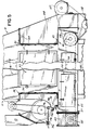
- the tailshaft comprises a housing 103 which has flanges as shown in Fig. 5 interconnected to the upstream end of the upstream-most side of the upstream modular classifier 11.
- Each of the chambers 45 in each module is provided with a circular cut-out, 104 and cover plate 105 (Fig. 3). These accommodate headshaft 101 and headstock 106 driven by any suitable motor 107 through any suitable pulley/sprocket and belt/chain drive.
- Both the headshaft and tailshaft 101, 102 may be horizontally adjustable to provide adequate take-up. It will be appreciated at the downstream or right hand end of Fig. 5, a nose piece 108 is secured by flanges 109 to the modular separator 14, covering opening 35 therein. Tobacco, other than lifted lights, discharging from chamber 17 of this module is directed toward a multiple vaned air lock 118 disposed beneath nose piece 108 for discharging tobacco onto a conveyor 127 as will be described. A common drive from motor 107 might be used to drive both the headstock 106 and airlock 118, as desired.
- the conveyor 58 can be extended through any number of classifiers by means of the headshaft and tailshaft 101 and 102 interconnecting on the ends of the various heavy removal chambers at the upstream and downstream ends of the apparatus.
- the head and tail shafts support end pulleys to support the conveyor.
- each module has a lower air plenum 110 defined in part by walls 111 and 112 from the sides and by a lower self-cleaning floor or discharge conveyor 113.
- Vanes 114, 115, and 116 are located in the air plenum as shown in Fig. 2 for directing air entering from duct 117 upwardly through the porous conveyor 58 into the classification chambers 17 of the respective modules. The bottoms of the vanes do not contact conveyor 113, and any dust or direct retained can fall onto conveyor 113.
- each module comprises or defines a closed-loop air system which is perhaps best seen in Figs. 1, 2, and 4.
- Blower 121 which can be a squirrel cage or any other suitable type, has an outlet duct 122 feeding into enlarged duct 117 and into the air plenum 110.
- Duct 117 at its lower end, can be provided with three internal vanes to spread the air across the duct.
- the air is directed by the vanes 114-116 in plenum 110 upwardly through the porous belt 58 into the classification chamber 17 where it engages or impinges on the projected stream of tobacco and lifts a light tobacco, such as lamina, through inlet 22 into the air separator 19.
- Rotating screen 20 serves to screen tobacco from the air stream. The air moves through the screen 20 into the duct 120 recirculating to blower 121, all in a closed loop fashion.
- each of the modules is provided at location 32 with a plurality of elongated slots 32a extending substantially across the width of chamber 17, for adjustably admitting make-up air. It will be appreciated that the air flow is shown by the heavy lined arrows in the Figs. while the tobacco flow is shown with dash line arrows.
- make up air may be admitted in slots 32a
- make up air is also preferably provided at locations identified at 150 (Fig. 5) and 151, 152, 153 and 154 (Fig. 3) in the various infeed means shown herein.
- the rotor infeeds have make-up air inlets such as 151, 152 and the belt infeeds have make-up air inlets 153, 154.
- Each air make-up is essentially of the same construction, including a plurality of staggered slots in the housing wall and a slide gate to partially open, fully open or close the slots.
- staggered slots 32a are shown in Fig. 2 at make-up air location 32.
- a slide plate 160 (at each air inlet location) has a pattern of staggered upper and lower slots 161, 162 corresponding to the staggered slot pattern 32a in the wall of the separator. Lips 163, 164 overlap plate 160 on its respective upper and lower margins. Tab 165 can be manually grasped to slide the plate 160 so its slots align with slots 32a, at least partially if not fully, to open the make-up air location, or to cover the slots 32a to cut off all make-up air.
- a motor 140 is arranged to drive a shaft 141 through a belt and pulley drive 142.
- Shaft 141 is connected to drive the blower 121 and rotating screen 20.
- Motor 140 and blower 121 are mounted on any suitable frame or support shown diagrammatically at 143.
- the self cleaning conveyor 113 is reversible and is carried by a plurality of rollers 124 or any other suitable means. Any suitable means, such as a reversible motor (not shown) can be used to drive conveyor 113.
- Conveyor 113 preferably includes sliding or wiper edges and forms a lower floor of the air plenum chamber 110. Any material which either drops off the conveyor 58, or which falls out of suspension in the air stream moving through ducts 122, 117 and air plenum 110 fall onto the conveyor 113 and can be removed in one of two ways.
- the conveyor 113 has an upper run and a lower run.
- the upper run When the upper run is moved to the right as viewed in Fig. 1, it discharges any material thereon onto a conveyor 127 which carries and deposits material thereon into an inlet 128 for conveyance through a pneumatic duct, for example, 129 to a downstream thresher 130.
- the porous conveyor 58 carrying stem and other heavies moves to the right as viewed in Fig. 1 and discharges through an appropriate multiple-vaned air lock 118 also onto the conveyor 127.
- any affluent foreign matter dust, etc. falling onto or collected on conveyor 113 is added back into the tobacco product for further treatment.
- Tobacco from the thresher is introduced to inlet 15 of the infeed means 60.
- the multiple vane rotor associated with that infeed means moves in a counterclockwise direction as viewed in Fig. 1 to project a mixed stream of tobacco including the light and heavy components across the classification chamber 17 of the first modular classifier 11.
- Air generated by blower 121 moves through ducts 122, 117 and down into air plenum 110 where the air is directed upwardly through the porous belt 58 to impinge on the projected tobacco stream. This lifts light components of the tobacco upwardly into the hood 18 in the classifier 11 for removal in separator 19 thereof and delivery onto collection conveyor 29 from where these lights are taken for further treatment.
- That infeed means is also a multiple vane rotor, in this configuration, which rotates in a counter-clockwise direction as viewed in Fig. 1 to project the stream of tobacco across the chamber 17 of separator 12.
- the operation of the separator 13 receiving this tobacco stream is similar to that described above for separators 11 and 12.
- the intermediate tobacco components passing across chamber 17 of separator 13 do not engage inlet 68 of a rotor-type infeed means, but rather are projected into the inlet 92 of the belt-type infeed means 63, as shown.
- the inclined belt runs at a speed to take tobacco falling thereon and project it across classification chamber 17 of separator 14.
- the infeed means 60-63 are preferably disposed at the same elevation and it is not necessary to piggyback or raise an upstream classifier above the next downstream classifier in order to provide a tobacco stream discharging across the classification chambers directly into the infeed of the next downstream classifier.
- each of the modules and each of the infeed means are interchangeable one with the other and a varying numbers of modules or infeed means can be used.
- conveyors such as conveyors 58 and conveyors 29, for example, are provided with side wipers, channelized belts or the like so that material is not disposed to fall from the conveyors.
- conveyor 29 is carried within its own housing 132 so that the lights received thereon can be discharged from the conveyor 29 into suitable collection means for further process.
- the invention provides a huge energy savings over prior separators where separate conveyors were required between each of the separators. This results in a significant saving of floor space and energy. Moreover, the self cleaning aspect provided by the conveyor 113 reduces downtime for cleaning and maintenance and provides for further processing as desired.
- Such a modular classifier provides as compared to prior systems of classifiers interconnected together by means of intervening conveying mechanisms, less capital cost, lower installation cost, and less installation time. It also provides lower maintenance cost.
- any of the infeed means can be interchanged depending on the particular result desired and that the system produces a smooth flow of tobacco therethrough without any undue surging.
- the recycled air from the respective blowers is preferably introduced in only one side of the air plenum. Air could be introduced into both sides thereof, with some change in the vanes, for particularly wide units.
- blower speeds and the rotor speeds can be adjusted to adjust the nature of the projected tobacco stream and the air flowing upwardly therethrough. Air velocities in the neighborhood of 500 ft. per min. or slightly above have been found to be suitable.
- adjustable vanes 78 can be utilized beneath each of the infeed rotors for controlling the inclination of the projected tobacco stream, while the inclination of the belt infeed means 63 could also be adjusted to the same end.
Landscapes
- Manufacturing Of Cigar And Cigarette Tobacco (AREA)
- Manufacture Of Tobacco Products (AREA)
Claims (28)
- Vorrichtung (10) zum Trennen von schwerem und leichten Materialfraktionen wie z.B. Tabakstiel und Tabakblätter, befördert in einem Mischstrom eines solchen Materials, umfassend einen Abscheider (11, 12, 13, 14) mit einer oberen Abscheiderkammer (17), mit dem Abscheider (11, 12, 13, 14) betriebsmäßig verbundene Zuführungsmittel (61, 62, 63, 64) mit einem Mittel zum Ausstoßen eines Mischstroms in die obere Abscheiderkammer (17) des Abscheiders (11, 12, 13, 14) über einen aufsteigenden Luftstrom, so daß leichtere Fraktionen nach oben abgeführt werden, während schwerere Fraktionen zur Entsorgung herunterfallen, und ein Fördermittel (58) zur Aufnahme von schwereren, aus dem Mischstrom herausfallenden Fraktionen, dadurch gekennzeichnet, daß die Vorrichtung (10) eine Mehrzahl solcher Trennabscheider (11, 12, 13, 14) umfaßt, dadurch, daß das Fördermittel (58) durch jeden Abscheider (11, 12, 13, 14) verläuft, um die schwereren Fraktionen durch nachfolgende abwärtige Abscheider (12, 13, 14) zu befördern, dadurch, daß jeder Abscheider (11, 12, 13), mit Ausnahme des letzten abwärtigen Abscheiders (14), Mittel zur Aufnahme (61, 62, 63, 64) von Restfraktionen in dem Strom aufweist, die nicht nach oben getragen wurden oder herausgefallen sind, und zum Liefern solcher Restfraktionen zu Ausstoßmitteln (61, 62, 63, 64) eines abwärtigen Abscheiders (12, 13, 14) und dadurch, daß die Abscheider (11, 12, 13, 14), mit Ausnahme des letzten abwärtigen Abscheiders, untereinander austauschbar sind, so daß die Vorrichtung (10) mit den Abscheidern (11, 12, 13, 14) in jeder beliebigen Reihenfolge gebildet werden kann.
- Vorrichtung nach Anspruch 1, bei der die Zuführungsmittel (61, 62, 63, 64) eines abwärtigen Abscheiders (12, 13, 14) das Mittel zur Aufnahme eines Teils eines ausgestoßenen Stroms aus einem aufwärtigen Abscheider (11, 12, 13) beinhaltet.
- Vorrichtung nach Anspruch 1 oder Anspruch 2, bei der die Zuführungsmittel (61, 62, 63, 64) zwischen den Abscheidern (11, 12, 13, 14) austauschbar ist.
- Vorrichtung nach einem der vorherigen Ansprüche, bei der die Abscheider (11, 12, 13, 14) betriebsmäßig wenigstens teilweise durch Befestigen der beteiligten Zuführungsmittel (61, 62, 63, 64) daran miteinander verbunden werden.
- Vorrichtung nach einem der vorherigen Ansprüche, mit einem Ablenkflügel (78), der in der Nähe jedes Zuführungsmittels (61, 62, 63, 64) angeordnet ist, um die Flugbahn des daraus ausgestoßenen Materials einzustellen.
- Vorrichtung nach einem der vorherigen Ansprüche, bei der die Zuführungsvorrichtung (61, 62, 63, 64) im Zusammenhang mit jedem Abscheider (11, 12, 13, 14) in einer gemeinsamen horizontalen Ebene angeordnet sind.
- Vorrichtung nach einem der vorherigen Ansprüche, bei der jeder Abscheider (11, 12, 13, 14) eine Kammer (45) zum Entfernen schwerer Fraktionen beinhaltet, in die schwerere Fraktionen fallen.
- Vorrichtung nach einem der vorherigen Ansprüche, bei der jeder Abscheider eine gemeinsame Förderkammer (45) unterhalb der Abscheiderkammer (17) aufweist, wobei durch alle diese Förderkammern (45) ein gemeinsamer Förderer (58) verläuft, wobei die Abscheider (11, 12, 13, 14) wenigstens teilweise durch Verbinden der gemeinsamen Förderkammern (45) miteinander verbunden sind.
- Vorrichtung nach Anspruch 8 in Abhängigkeit von Anspruch 7, bei der die Förderkammer jedes Abscheiders deren Kammer (45) zum Entfernen schwerer Fraktionen umfaßt, wobei der Förderer ein Förderer (58) zum Abführen schwerer Fraktionen ist.
- Vorrichtung nach Anspruch 9, bei der der Förderer zum Abführen schwerer Fraktionen eine poröse Schürze (58) ist, wobei die Vorrichtung (10) ferner eine vordere Schürzenwelle (101) und eine hintere Schürzenwelle (102) aufweist, wobei die vordere und die hintere Welle (101, 102) auf jeweiligen abwärtigen und aufwärtigen Seiten von abwärtigen und aufwärtigen Abscheidern (11, 12, 13, 14) orientiert sind und die Schürze (58) betriebsmäßig so montieren, daß sie durch die Zwischenkammer (45) zum Entfernen schwerer Fraktionen jedes Abscheiders (11, 12, 13, 14) verläuft, um schwere Fraktionen des aus jeder Abscheidungskammer (17) herausfallenden Gemisches aufzunehmen und abzuführen.
- Vorrichtung nach Anspruch 10, bei der die vordere Welle (101) in der Kammer (45) zum Entfernen schwerer Fraktionen des abwärtigen Abscheiders (14) montiert ist und bei der die hintere Welle (102) in der Nähe eines aufwärtigen Endes der Kammer (45) zum Entfernen schwerer Fraktionen des aufwärtigen Abscheiders (11) montiert ist.
- Vorrichtung nach einem der Ansprüche 8 bis 10, die einen zweiten Förderer (113) aufweist.
- Vorrichtung nach Anspruch 12, bei der der zweite Förderer (113) unterhalb des Förderers (58) zum Abführen schwerer Fraktionen angeordnet ist.
- Vorrichtung nach Anspruch 12 oder Anspruch 13, bei der der zweite Förderer umkehrbar ist.
- Vorrichtung nach einem der vorherigen Ansprüche, bei der jeder Abscheider einen unteren Lufteinlaßraum (110) und Mittel (114, 115, 116) in dem unteren Lufteinlaßraum (110) aufweist, um einen Strom von Abscheidungsluft nach oben durch die Abscheidungskammer (17) zu leiten.
- Vorrichtung nach Anspruch 15 in Abhängigkeit von einem der Ansprüche 12 bis 14, bei der der zweite Förderer durch untere Teile der unteren Lufteinlaßräume (110) verläuft, um Abfälle und Reste aus jedem Abscheider zu sammeln.
- Vorrichtung nach Anspruch 16, bei der das Luftstromleitmittel Flügel (114, 115, 116) aufweist, um Luft im unteren Lufteinlaßraum (110) nach oben in Richtung auf die Abscheiderkammer (17) zu leiten, wobei die Flügel (114, 115, 116) in bezug auf den Luftstrom über dem zweiten Förderer (113) aufwärtige Enden aufweisen.
- Vorrichtung nach einem der vorherigen Ansprüche, bei der jeder Abscheider (11, 12, 13, 14) einen geschlossenen Strömungskreislauf für Abscheidungsluft definiert, wobei Kreislauf und Strömung durch die Abscheidungskammer (17) verlaufen.
- Vorrichtung nach Anspruch 18 in Abhängigkeit von einem der Ansprüche 15 bis 17, bei der jeder Abscheider ferner ein Gebläse (121) zur Aufnahme von Luft von den Empfangsmitteln (61, 62, 63, 64) und zum Blasen von Abscheidungsluft in den unteren Lufteinlaßraum (110) und nach oben durch die Abscheidungskammer (19) aufweist, wobei die Abscheidungsluft in dem geschlossenen Kreislauf von der Abscheidungskammer (17) durch die Strömungsleitmittel (114, 115, 116) und zurück in die Abscheidungskammer (17) strömt.
- Vorrichtung nach einem der vorherigen Ansprüche, bei der jeder Abscheider ferner eine Kammer (18) zum Entfernen leichter Fraktionen aufweist, die betriebsmäßig über der Abscheidungskammer (17) angeordnet ist, ein Mittel (19) zum Filtern der leichten Fraktionen aus einem Luftstrom zum Befördern leichter Fraktionen, und Mittel (24, 26, 28) zum Sammeln der leichten Fraktionen außerhalb des Luftstroms.
- Vorrichtung nach einem der vorherigen Ansprüche, bei der die Ausstoßmittel (61, 62, 63, 64) in allen Abscheidungskammern (17) in derselben horizontalen Ebene angeordnet sind.
- Vorrichtung nach einem der vorherigen Ansprüche, bei der das Materialaufnahmemittel und die Ausstoßmittel einen Bandförderer (63) mit einem Materialaufnahmeende und einem Materialausstoßende umfassen.
- Vorrichtung nach einem der vorherigen Ansprüche, bei der die Abscheider (11, 12, 13, 14) serienmäßig und betriebsmäßig über dieselbe horizontale Anordnung miteinander verbunden sind.
- Vorrichtung nach einem der vorherigen Ansprüche, bei der die Vorrichtung (10) eine Mehrzahl von austauschbaren Modulen umfaßt, wobei jedes Modul einen Abscheider (11, 12, 13, 14) und vorzugsweise auch ein Zuführungsmittel (61, 62, 63, 64) umfaßt.
- Abscheider (11, 12, 13, 14) zur Verwendung in einer Trennvorrichtung (10) zum Trennen leichter Fraktionen von schwereren Fraktionen in einem Gemisch davon, wobei der Abscheider ein Senkrechthub-Einzeldurchgang-Abscheider (11, 12, 13, 14) mit einer Abscheidungskammer (17) ist, eine Kammer (45) zum Entfernen von schweren Fraktionen, die unterhalb der Abscheidungskammer (17) angeordnet ist, ein Lufteinlaßraum (110) unterhalb der Kammer (45) zum Entfernen schwerer Fraktionen, eine Einlaßöffnung (34) in der Abscheidungskammer (17) und eine Auslaßöffnung (35) in der Abscheidungskammer (17), wobei der Abscheider (11, 12, 13, 14) Ausstoßmittel (61, 62, 63, 64) aufweist, die betriebsmäßig mit der Einlaßöffnung (34) in der Abscheidungskammer (17) zum Aufnehmen von Mischmaterial verbunden sind und das aufgenommene Material über die Abscheidungskammer (17) ausstoßen, dadurch gekennzeichnet, daß der Abscheider (11, 12, 13, 14) ein Modul für die Verwendung mit anderen Modulen ist, mit denen es austauschbar ist, dadurch, daß die Kammer (45) zum Entfernen schwerer Fraktionen zum Aufnehmen eines gemeinsamen Förderers (58) dient und auf- und abwärtige Enden hat, dadurch, daß das Modul Mittel (46, 47, 48, 49) am aufwärtigen und am abwärtigen Ende der Kammer (45) zum Entfernen schwerer Fraktionen aufweist, die mit Enden jeweiliger Kammern (45) zum Entfernen schwerer Fraktionen benachbarter Module verbunden werden, so daß der Förderer (58) durch die Kammern (45) verlaufen kann, und dadurch, daß die Ausstoßmittel (61, 62, 63, 64) dazu dienen, über die Abscheidungskammer (17) eines vorgeschalteten Moduls in die Einlaßöffnung (34) ausgestoßenes Mischmaterial aufzunehmen, wenn die Module verbunden sind, und aufgenommenen Tabak über das Modul auszustoßen, und dadurch, daß die Ausstoßmittel (61, 62, 63, 64) betriebsmäßig mit dem Auslaß (35) eines vorgeschalteten Moduls verbunden werden können.
- Abscheider nach Anspruch 25, ferner umfassend eine Kammer (18) zum Entfernen leichter Fraktionen, die über der Abscheidungskammer (17) angeordnet ist, und ein Mittel zum Erzeugen und Definieren eines geschlossenen Abscheidungsluftkreislaufs zum Blasen von Abscheidungsluft nach oben in die Abscheidungskammer (17) von dem Lufteinlaßraum in die genannte Kammer (18) zum Entfernen leichter Fraktionen und zurück in den Lufteinlaßraum (110).
- Verfahren zum Trennen von schweren und leichten Materialfraktionen, die in einem Mischstrom von Materialfraktionen befördert werden, umfassend die folgenden Schritte: Ausstoßen eines Stroms von Mischmaterial progressiv über eine Abscheidungskammer eines Abscheiders, Blasen von Luft nach oben in die Kammer, um leichtere Materialfraktionen abzuheben, Aufnehmen schwererer Niederschlagsfraktionen von Material in einem unteren Teil der Kammer, dadurch gekennzeichnet, daß der Strom über die Abscheidungskammer einer Mehrzahl von betriebsmäßig miteinander verbundenen, austauschbaren Abscheidern ausgestoßen wird, dadurch, daß die schwereren Fraktionen auf einem gemeinsamen Förderer aufgenommen und horizontal in aufeinanderfolgende abwärtige Abscheider befördert werden, und dadurch, daß das Verfahren die Aufnahme eines Mischstroms von Material beinhaltet, der nicht abgehoben wurde oder niedergeschlagen ist, auf einer abwärtigen Seite jeder Kammer bei einer vertikalen Anordnung im wesentlichen auf derselben horizontalen Ebene wie der Ort, von dem der Mischstrom ausgestoßen wurde, und, mit Ausnahme des letzten abwärtigen Abscheiders, Ausstoßen des Mischstroms über die Abscheidungskammer des nächsten abwärtigen Abscheiders zur weiteren Abscheidung.
- Verfahren nach Anspruch 27, beinhaltend das Aufnehmen von Material, das unter den gemeinsamen Förderer auf einen zweiten, darunter befindlichen gemeinsamen Förderer fällt, und selektives Transportieren des Materials zu einer abwärtigen oder aufwärtigen Stelle in bezug auf die Mehrzahl von Abscheidern für die Entladung oder zum Vermischen mit einem Mischstrom aus Material zur weiteren Abscheidung.
Applications Claiming Priority (3)
| Application Number | Priority Date | Filing Date | Title |
|---|---|---|---|
| US07/727,974 US5205415A (en) | 1991-07-10 | 1991-07-10 | Modular classifier |
| US727974 | 1991-07-10 | ||
| PCT/US1992/005743 WO1993000833A1 (en) | 1991-07-10 | 1992-07-09 | Modular classifier |
Publications (2)
| Publication Number | Publication Date |
|---|---|
| EP0594730A1 EP0594730A1 (de) | 1994-05-04 |
| EP0594730B1 true EP0594730B1 (de) | 1997-05-28 |
Family
ID=24924894
Family Applications (1)
| Application Number | Title | Priority Date | Filing Date |
|---|---|---|---|
| EP92915533A Expired - Lifetime EP0594730B1 (de) | 1991-07-10 | 1992-07-09 | Modularer sichter |
Country Status (7)
| Country | Link |
|---|---|
| US (2) | US5205415A (de) |
| EP (1) | EP0594730B1 (de) |
| AU (1) | AU2337592A (de) |
| BR (1) | BR9206257A (de) |
| DE (1) | DE69220065D1 (de) |
| WO (1) | WO1993000833A1 (de) |
| ZW (1) | ZW10992A1 (de) |
Families Citing this family (30)
| Publication number | Priority date | Publication date | Assignee | Title |
|---|---|---|---|---|
| US5325875A (en) * | 1987-08-24 | 1994-07-05 | Universal Leaf Tobacco Co., Inc. | Apparatus for separating threshed leaf tobacco |
| US5205415A (en) * | 1991-07-10 | 1993-04-27 | The Standard Commercial Tobacco Co., Inc. | Modular classifier |
| US5361909A (en) * | 1993-03-31 | 1994-11-08 | Gemmer Bradley K | Waste aggregate mass density separator |
| US5394893A (en) * | 1993-10-22 | 1995-03-07 | Universal Leaf Tobacco Co., Ltd. | Modular style multi-separator |
| US6897016B1 (en) | 1993-11-12 | 2005-05-24 | The Regents Of The University Of Colorado | Alteration of sequence of a target molecule |
| US5667969A (en) * | 1993-11-12 | 1997-09-16 | University Research Corporation | Alteration of sequence of a deleterious target molecule by ribozyme catalyzed trans-splicing |
| US5538017A (en) * | 1994-09-28 | 1996-07-23 | Monk-Austin International, Inc. | Tobacco leaf separator |
| US5804434A (en) * | 1994-10-17 | 1998-09-08 | Cash; Alan Brian | Process for removing solvent from soil and debris |
| US5427248A (en) * | 1994-10-20 | 1995-06-27 | Mactavish Machine Manufacturing Co. | Apparatus for the separation of tobacco lamina from tobacco stem |
| DE4441099A1 (de) * | 1994-11-18 | 1996-05-23 | Koch Industrieanlagen Gmbh | Hochleistungssichter |
| US5727690A (en) * | 1995-10-05 | 1998-03-17 | Hofmeister; William M. | Method and apparatus for processing leafy vegetables |
| US6250471B1 (en) | 1999-02-24 | 2001-06-26 | Key Technology, Inc. | Sorting apparatuses and sorting methods |
| US6435191B1 (en) | 1999-02-26 | 2002-08-20 | Dimon Inc. | Tobacco separator |
| FI110171B (fi) * | 2000-09-20 | 2002-12-13 | Andritz Oy | Laitteen käyttö puuhakkeen jaottelemiseksi eri fraktioihin |
| US7060675B2 (en) * | 2001-02-15 | 2006-06-13 | Nobex Corporation | Methods of treating diabetes mellitus |
| KR100385895B1 (en) * | 2002-07-24 | 2003-06-02 | Seo Won Environ Ment Co Ltd | Apparatus for sorting construction waste |
| CA2499853C (en) * | 2004-03-15 | 2012-11-13 | Universal Leaf Tobacco Company, Inc. | Apparatus and method for scanning and sorting tobacco leaves |
| JP5151940B2 (ja) * | 2008-12-03 | 2013-02-27 | 株式会社リコー | 分級装置 |
| US8281931B2 (en) * | 2009-09-18 | 2012-10-09 | Key Technology, Inc. | Apparatus and method for post-threshing inspection and sorting of tobacco lamina |
| CN102178338A (zh) * | 2011-04-15 | 2011-09-14 | 云南昆船设计研究院 | 一种烟叶回梗循环风选方法及设备 |
| CN103263075B (zh) * | 2013-06-11 | 2015-08-12 | 红塔烟草(集团)有限责任公司 | 高效节能打叶风分新工艺及设备 |
| US10434545B2 (en) * | 2014-01-17 | 2019-10-08 | United Technologies Corporation | Particle separator for an additive manufacturing system and method of operation |
| UA111922C2 (uk) * | 2015-05-25 | 2016-06-24 | Олена Іванівна Кострубяк | Аеродинамічний рециркуляційний сепаратор сипучих матеріалів |
| US9999892B2 (en) | 2015-09-03 | 2018-06-19 | Drsw, Llc | Method and apparatus of processing whole tobacco plants |
| CN108851185A (zh) * | 2018-07-30 | 2018-11-23 | 重庆烟叶复烤有限公司万州复烤厂 | 一种精准打叶风分方法 |
| CN109662337A (zh) * | 2018-11-19 | 2019-04-23 | 红塔烟草(集团)有限责任公司 | 一种基于均质化的打叶复烤过程质量控制方法 |
| CN113399263A (zh) * | 2021-07-06 | 2021-09-17 | 向光联 | 一种石英砂风选设备及其使用方法 |
| KR102713041B1 (ko) | 2023-02-03 | 2024-10-02 | 차이나 타바코 윈난 인더스트리얼 컴퍼니 리미티드 | 각초 제조라인용 각초 이물질 제거 장치 및 각초 이물질 제거 방법 |
| CN116195760B (zh) * | 2023-02-03 | 2025-04-25 | 云南中烟工业有限责任公司 | 一种制丝生产线烟丝异物去除装置及烟丝异物去除方法 |
| US11944116B1 (en) | 2023-02-13 | 2024-04-02 | China Tobacco Yunnan Industrial Co., Ltd. | Device and method for removing unwanted objects from cut tobacco in a cut tobacco production line |
Family Cites Families (64)
| Publication number | Priority date | Publication date | Assignee | Title |
|---|---|---|---|---|
| US518082A (en) * | 1894-04-10 | Mortimer stucke | ||
| NL47566C (de) * | ||||
| US974395A (en) * | 1909-02-03 | 1910-11-01 | George Chandler Kidder | Ore concentrator or separator. |
| US1530277A (en) * | 1922-11-13 | 1925-03-17 | Wonder Grain Cleaner Company | Grain cleaner |
| US1863666A (en) * | 1927-03-19 | 1932-06-21 | United Cigarette Mach Co Inc | Method of and apparatus for loosening tobacco particles and frering them from dust |
| US1903931A (en) * | 1930-03-18 | 1933-04-18 | Molins Walter Everett | Apparatus for supplying tobacco to a cigarette making machine |
| US1962668A (en) * | 1931-09-24 | 1934-06-12 | George J Olney | String bean cleaner |
| DE630756C (de) * | 1934-12-18 | 1936-06-05 | Edwin Hoffmann Dr Ing | Windsichter |
| US2173088A (en) * | 1935-09-19 | 1939-09-19 | Muller J C & Co | Separating device |
| US2130880A (en) * | 1935-10-03 | 1938-09-20 | Int Cigar Mach Co | Tobacco stemming and threshing machine |
| US2275849A (en) * | 1936-08-24 | 1942-03-10 | Fraser Thomas | Apparatus for separating mixed materials |
| FR828904A (fr) * | 1936-11-09 | 1938-06-03 | Fu R Forderanlagen Ernst Hecke | Procédé pour séparer les particules pulvérulentes de poids spécifiques différents contenues dans une matière mêlée |
| US2667174A (en) * | 1947-11-28 | 1954-01-26 | American Machine Dev Corp | Apparatus and method for ripping and assorting tobacco leaves |
| US2658617A (en) * | 1950-02-04 | 1953-11-10 | Imp Tobacco Co Ltd | Tobacco cleaner and classifier |
| GB685417A (en) * | 1950-03-17 | 1953-01-07 | American Tobacco Co | Improvements in process of and apparatus for treating tobacco |
| NL85696C (de) * | 1953-02-20 | |||
| US2825457A (en) * | 1953-07-15 | 1958-03-04 | Imp Tobacco Co Ltd | Tobacco cleaner and classifier |
| GB755252A (en) * | 1954-02-23 | 1956-08-22 | Vokes Ltd | Apparatus for classifying particles by size |
| US2852137A (en) * | 1956-06-05 | 1958-09-16 | Commercial Mfg & Supply Co | Raisin cleaner |
| US2988213A (en) * | 1956-11-19 | 1961-06-13 | American Mach & Foundry | Tobacco separating apparatus |
| US2941667A (en) * | 1957-04-16 | 1960-06-21 | Brown & Williamson Tobacco Corp | Leaf tobacco separator and method |
| FR1195742A (fr) * | 1957-05-11 | 1959-11-19 | Quester Fa Wilh | Dispositif pour l'écôtage de feuilles de tabac |
| US2944629A (en) * | 1957-08-09 | 1960-07-12 | American Mach & Foundry | Tobacco separating apparatus |
| US3010576A (en) * | 1957-12-24 | 1961-11-28 | Hauni Werke Koerber & Co Kg | Apparatus for separating or winnowing tobacco and other like fibrous material |
| US3074413A (en) * | 1959-03-13 | 1963-01-22 | American Mach & Foundry | Cigarette making machine |
| US3034646A (en) * | 1959-08-27 | 1962-05-15 | American Mach & Foundry | Tobacco classifying apparatus |
| DE1152340B (de) * | 1960-10-31 | 1963-08-01 | Hauni Werke Koerber & Co Kg | Vorrichtung zum Sichten von Tabak |
| NL264715A (de) * | 1960-05-16 | |||
| DE1124414B (de) * | 1960-10-04 | 1962-02-22 | Hauni Werke Koerber & Co Kg | Vorrichtung zum Sichten von Tabak |
| US3164548A (en) * | 1961-06-15 | 1965-01-05 | Imp Tobacco Co Ltd | Tower type pneumatic separator |
| DE1150013B (de) * | 1961-06-22 | 1963-06-06 | Hauni Werke Koerber & Co Kg | Vorrichtung zum stufenweisen Sichten von Tabak und aehnlichem Gut |
| US3240335A (en) * | 1961-12-11 | 1966-03-15 | Buell Engineering Company Inc | Classifier with gas flow distributor |
| US3378140A (en) * | 1962-03-27 | 1968-04-16 | Hauni Werke Koerber & Co Kg | Method and apparatus for pneumatically separating solid particles |
| GB1022471A (en) * | 1962-05-09 | 1966-03-16 | Korber Kurt | Improvements in methods and devices for separating tobacco and like material |
| NL295148A (de) * | 1962-07-18 | |||
| GB1077410A (en) * | 1964-12-24 | 1967-07-26 | Kurt Koerber | Apparatus for stripping and separating tobacco or other foliate materials |
| US3360125A (en) * | 1965-02-09 | 1967-12-26 | John B Adt Company | Tobacco-leaf separator |
| DE1532055A1 (de) * | 1965-09-03 | 1970-01-08 | Hauni Werke Koerber & Co Kg | Verfahren und Entrippanlage zum Entrippen von Tabak durch Zerkleinern mit nachfolgendem Sichten |
| CH468853A (de) * | 1965-10-20 | 1969-02-28 | Buehler Ag Geb | Vorrichtung zur schleierartigen Austragung von Schüttgut |
| FR1473911A (fr) * | 1965-11-17 | 1967-03-24 | Seita | Procédé et appareil pour écoter les feuilles de tabac et séparer les produits obtenus |
| DE1532092B2 (de) * | 1965-11-03 | 1976-04-22 | Vorrichtung zum entrippen von tabakblaettern und sichten des erhaltenen gutes | |
| US3397782A (en) * | 1966-01-19 | 1968-08-20 | Chao C. Kwong | Material separator |
| US3542037A (en) * | 1968-02-23 | 1970-11-24 | American Mach & Foundry | Cut tobacco stemmer |
| US3608716A (en) * | 1969-01-27 | 1971-09-28 | Imp Tobacco Co Ltd | Recirculating pneumatic separator |
| DE1932312A1 (de) * | 1969-06-26 | 1971-01-21 | Hauni Werke Koerber & Co Kg | Vorrichtung zum pneumatischen Heraussichten von Tabakrippen aus einem Gemisch von Tabakblatteilen und Tabakrippen |
| US3593851A (en) * | 1969-09-11 | 1971-07-20 | Amf Inc | Tobacco leaf classifier |
| US3727755A (en) * | 1970-02-23 | 1973-04-17 | Amf Inc | Pneumatic separator for a stream of cut tobacco |
| DE2506839C2 (de) * | 1975-02-18 | 1987-04-23 | Hauni-Werke Körber & Co KG, 2050 Hamburg | Vorrichtung zum Bilden eines Tabakfüllstromes |
| US3986949A (en) * | 1975-07-07 | 1976-10-19 | Duca Mark B Di | Air classifier |
| US4045334A (en) * | 1976-05-28 | 1977-08-30 | Amf Incorporated | Method and apparatus for separating lighter and heavier portions of threshed tobacco |
| US4213852A (en) * | 1979-01-15 | 1980-07-22 | Bernard Etkin | Method and apparatus for particle classification |
| US4253940A (en) * | 1979-09-24 | 1981-03-03 | Watson Energy Systems, Inc. | Method and apparatus for separating waste materials |
| US4475562A (en) * | 1981-10-16 | 1984-10-09 | Philip Morris Incorporated | Method and apparatus for separating tobacco mixture into lighter and heavier fractions |
| US4405451A (en) * | 1981-10-20 | 1983-09-20 | Bancohio National Bank | Air separation apparatus and system |
| US4411038A (en) * | 1981-11-16 | 1983-10-25 | Shinichi Mukai | Pneumatic cleaning system |
| US4465194A (en) * | 1982-12-23 | 1984-08-14 | Universal Leaf Tobacco Co. | Threshed tobacco lead separator |
| FR2543456B1 (fr) * | 1983-04-01 | 1986-04-11 | Femia | Procede et dispositif de separation gravimetrique et aerodynamique d'un melange heterogene de corps comprenant des produits et dechets de densites respectivement differentes |
| GB8409766D0 (en) * | 1984-04-14 | 1984-05-23 | Hambro Machinery Ltd | Flutriator |
| US4618415A (en) * | 1984-08-31 | 1986-10-21 | Amf Incorporated | Tobacco separator |
| US4915824A (en) * | 1985-08-12 | 1990-04-10 | Surtees Guy F | Pneumatic classifier for tobacco and method |
| US4701256A (en) * | 1985-12-13 | 1987-10-20 | The Cardwell Machine Company | Recirculating pneumatic separator |
| US5099863A (en) * | 1987-08-24 | 1992-03-31 | Universal Leaf Tobacco Co., Inc. | Apparatus for separating threshed leaf tobacco |
| GB2231770B (en) * | 1989-05-26 | 1993-03-10 | Cardwell Machine Company | Apparatus and method for processing inhomogeneous material such as tobacco |
| US5205415A (en) * | 1991-07-10 | 1993-04-27 | The Standard Commercial Tobacco Co., Inc. | Modular classifier |
-
1991
- 1991-07-10 US US07/727,974 patent/US5205415A/en not_active Expired - Lifetime
-
1992
- 1992-07-09 DE DE69220065T patent/DE69220065D1/de not_active Expired - Lifetime
- 1992-07-09 WO PCT/US1992/005743 patent/WO1993000833A1/en not_active Ceased
- 1992-07-09 AU AU23375/92A patent/AU2337592A/en not_active Abandoned
- 1992-07-09 BR BR9206257A patent/BR9206257A/pt not_active IP Right Cessation
- 1992-07-09 ZW ZW109/92A patent/ZW10992A1/xx unknown
- 1992-07-09 EP EP92915533A patent/EP0594730B1/de not_active Expired - Lifetime
-
1993
- 1993-03-29 US US08/038,707 patent/US5358122A/en not_active Expired - Fee Related
Also Published As
| Publication number | Publication date |
|---|---|
| BR9206257A (pt) | 1995-12-12 |
| ZW10992A1 (en) | 1992-10-28 |
| AU2337592A (en) | 1993-02-11 |
| US5358122A (en) | 1994-10-25 |
| EP0594730A1 (de) | 1994-05-04 |
| WO1993000833A1 (en) | 1993-01-21 |
| US5205415A (en) | 1993-04-27 |
| DE69220065D1 (de) | 1997-07-03 |
Similar Documents
| Publication | Publication Date | Title |
|---|---|---|
| EP0594730B1 (de) | Modularer sichter | |
| US4701256A (en) | Recirculating pneumatic separator | |
| US4915824A (en) | Pneumatic classifier for tobacco and method | |
| US5394893A (en) | Modular style multi-separator | |
| US5476109A (en) | Apparatus for separating threshed leaf tobacco | |
| US4278532A (en) | Air classification apparatus | |
| US4586658A (en) | Impact grinding method and apparatus | |
| EP0479549B1 (de) | Vorrichtung zum Sichten von entrippten Tabakblättern und Verfahren | |
| US5427248A (en) | Apparatus for the separation of tobacco lamina from tobacco stem | |
| CN106690396A (zh) | 一种提高风分效率并降低物料造碎率的风分工艺及装置 | |
| RU189228U1 (ru) | Машина воздушно-решетной очистки вороха семян | |
| US3034646A (en) | Tobacco classifying apparatus | |
| WO1990014020A1 (en) | Apparatus and method for processing inhomogeneous material such as tobacco | |
| CN212041490U (zh) | 一种移动式高效环保粮食杂质清理装置 | |
| RU2464111C1 (ru) | Зерноочистительная машина | |
| US4226704A (en) | Collector discharge apparatus | |
| CN224168007U (zh) | 一种燃料棒生产用风选机 | |
| RU2834712C1 (ru) | Пневмосистема зерноочистительной машины | |
| CN115956702B (zh) | 一种烟叶分离设备 | |
| CN218835200U (zh) | 谷物清选机 | |
| RU2283704C2 (ru) | Зерноочистительная машина | |
| RU1828773C (ru) | Устройство дл обработки и приема зернового вороха | |
| CA1286632C (en) | Pneumatic classifier for tobacco and method | |
| US328269A (en) | Middlings-purifier | |
| CN106690397A (zh) | 一种风力浮选柔性落料工艺及设备 |
Legal Events
| Date | Code | Title | Description |
|---|---|---|---|
| PUAI | Public reference made under article 153(3) epc to a published international application that has entered the european phase |
Free format text: ORIGINAL CODE: 0009012 |
|
| 17P | Request for examination filed |
Effective date: 19940105 |
|
| AK | Designated contracting states |
Kind code of ref document: A1 Designated state(s): DE GB IT |
|
| 17Q | First examination report despatched |
Effective date: 19950321 |
|
| GRAG | Despatch of communication of intention to grant |
Free format text: ORIGINAL CODE: EPIDOS AGRA |
|
| GRAH | Despatch of communication of intention to grant a patent |
Free format text: ORIGINAL CODE: EPIDOS IGRA |
|
| GRAH | Despatch of communication of intention to grant a patent |
Free format text: ORIGINAL CODE: EPIDOS IGRA |
|
| GRAA | (expected) grant |
Free format text: ORIGINAL CODE: 0009210 |
|
| AK | Designated contracting states |
Kind code of ref document: B1 Designated state(s): DE GB IT |
|
| REF | Corresponds to: |
Ref document number: 69220065 Country of ref document: DE Date of ref document: 19970703 |
|
| PGFP | Annual fee paid to national office [announced via postgrant information from national office to epo] |
Ref country code: DE Payment date: 19970718 Year of fee payment: 6 |
|
| PG25 | Lapsed in a contracting state [announced via postgrant information from national office to epo] |
Ref country code: DE Effective date: 19970829 |
|
| PLBE | No opposition filed within time limit |
Free format text: ORIGINAL CODE: 0009261 |
|
| STAA | Information on the status of an ep patent application or granted ep patent |
Free format text: STATUS: NO OPPOSITION FILED WITHIN TIME LIMIT |
|
| 26N | No opposition filed | ||
| REG | Reference to a national code |
Ref country code: GB Ref legal event code: IF02 |
|
| PGFP | Annual fee paid to national office [announced via postgrant information from national office to epo] |
Ref country code: GB Payment date: 20020613 Year of fee payment: 11 |
|
| PG25 | Lapsed in a contracting state [announced via postgrant information from national office to epo] |
Ref country code: GB Free format text: LAPSE BECAUSE OF NON-PAYMENT OF DUE FEES Effective date: 20030709 |
|
| GBPC | Gb: european patent ceased through non-payment of renewal fee |
Effective date: 20030709 |
|
| PGFP | Annual fee paid to national office [announced via postgrant information from national office to epo] |
Ref country code: IT Payment date: 20060731 Year of fee payment: 15 |
|
| PG25 | Lapsed in a contracting state [announced via postgrant information from national office to epo] |
Ref country code: IT Free format text: LAPSE BECAUSE OF NON-PAYMENT OF DUE FEES Effective date: 20070709 |