EP0594855A1 - Chaussure avec bon-bout rempla able - Google Patents
Chaussure avec bon-bout rempla able Download PDFInfo
- Publication number
- EP0594855A1 EP0594855A1 EP92916807A EP92916807A EP0594855A1 EP 0594855 A1 EP0594855 A1 EP 0594855A1 EP 92916807 A EP92916807 A EP 92916807A EP 92916807 A EP92916807 A EP 92916807A EP 0594855 A1 EP0594855 A1 EP 0594855A1
- Authority
- EP
- European Patent Office
- Prior art keywords
- lift
- heel
- engagement
- hook
- hole
- Prior art date
- Legal status (The legal status is an assumption and is not a legal conclusion. Google has not performed a legal analysis and makes no representation as to the accuracy of the status listed.)
- Withdrawn
Links
Images







Classifications
-
- A—HUMAN NECESSITIES
- A43—FOOTWEAR
- A43B—CHARACTERISTIC FEATURES OF FOOTWEAR; PARTS OF FOOTWEAR
- A43B21/00—Heels; Top-pieces or top-lifts
- A43B21/36—Heels; Top-pieces or top-lifts characterised by their attachment; Securing devices for the attaching means
- A43B21/47—Heels; Top-pieces or top-lifts characterised by their attachment; Securing devices for the attaching means by resilient means
- A43B21/48—Heels; Top-pieces or top-lifts characterised by their attachment; Securing devices for the attaching means by resilient means by press-buttons
-
- A—HUMAN NECESSITIES
- A43—FOOTWEAR
- A43B—CHARACTERISTIC FEATURES OF FOOTWEAR; PARTS OF FOOTWEAR
- A43B21/00—Heels; Top-pieces or top-lifts
- A43B21/36—Heels; Top-pieces or top-lifts characterised by their attachment; Securing devices for the attaching means
- A43B21/37—Heels; Top-pieces or top-lifts characterised by their attachment; Securing devices for the attaching means by hook-shaped or bent attaching means
-
- A—HUMAN NECESSITIES
- A43—FOOTWEAR
- A43B—CHARACTERISTIC FEATURES OF FOOTWEAR; PARTS OF FOOTWEAR
- A43B21/00—Heels; Top-pieces or top-lifts
- A43B21/36—Heels; Top-pieces or top-lifts characterised by their attachment; Securing devices for the attaching means
- A43B21/50—Heels; Top-pieces or top-lifts characterised by their attachment; Securing devices for the attaching means by bayonet catches or the like
Definitions
- the present invention relates to the structure of a heel portion (hereinafter referred simply to as a heel) of a high heel shoe or the like of which lower end portion that is called a lift can be exchanged with a new one.
- a conventional high heel shoe is also constructed such that its lift can be exchanged with a new one.
- the high heel shoe includes a lift 1 which is integrated with a connection shaft 2 having a substantially semicircular sectional shape, and the connection shaft 2 is slightly tapered in the upward direction such that its upper end has a slightly reduced sectional area.
- a receiving hole 4 having the same sectional shape as that of the connection shaft 1 is formed through the bottom surface of a heel 3 of the high heel shoe so that the connection shaft 2 is fitted into the receiving hole 4.
- an inner diametrical dimension of the receiving hole 4 is determined to be slightly smaller than an outer diametrical dimension of the connection shaft 2.
- connection shaft 2 is tightly received in the receiving hole 4, it is practically impossible for an unskilled person to disconnect the connection shaft 2 from the receiving hole 4 irrespective of how a high intensity of pulling force is imparted to the connection shaft 2, because the frictional engagement of the connection shaft 2 with the receiving hole 4 is remarkably increased after she wears her high heel shoe for a long time. For this reason, she is unavoidably required to bring her worn high heel shoe to a well-skilled repairing shop in which the worn lift 1 is disconnected from the receiving hole 4 of the heel 3 by actuating a special tool.
- Another problem is that there is a possibility that the surface of the heel 3 is injured or scratched when the worn lift 1 is disconnected from the heel 3 with a high intensity of pulling force imparted to the lift 1 by actuating a certain tool.
- the present invention has been made in consideration of the aforementioned background and its object resides in providing a shoe which assures that a worn heel can easily be exchanged with a new one by any unskilled person.
- a shoe including an exchangeable lift wherein the shoe is characterized in that an anchor plate having a plurality of hook-shaped engagement projections formed thereon is embedded in the upper part of the lift while extending substantially in parallel with the upper surface of the lift in such a manner as to allow the hook-shaped engagement projections to be projected upward of the upper surface of the lift, that an engagement plate is fixedly secured to the lower end surface of a heel located opposite to the upper surface of the lift while extending substantially in parallel with the upper surface of the lift, that a plurality of engagement holes are formed on the engagement plate corresponding to the hook-shaped engagement projections in such a manner that the upper ends of the hook-shaped engagement projections are first inserted through the engagement holes when the upper surface of the lift is located at the insertion/detachment position where the lift is permitted to move along the lower end surface of the heel in the horizontal direction, and thereafter, the horizontal portions of the hook-shaped engagement projections are
- the shoe is constructed in the above-described manner according to the invention as defined by claim 1 of the claim clause, while the lift is seized at the insertion/detachment position relative to the heel with an operator's hand, the upper surface of the lift is brought in contact with the lower end surface of the heel. At this time, the upper ends of the hook-shaped engagement projections projecting upward of the upper surface of the lift are inserted into the engagement holes formed on the engagement plate.
- the lift As the lift is displaced toward the attachment position relative to the heel while maintaining the foregoing state, the lift moves in the horizontal direction while the upper surface of the lift is brought in slidable contact with the lower surface of the heel. At the same time, the vertical portions of the hook-shaped projections are displaced toward the other ends of the respective engagement holes. When the lift reaches the attachment position, the horizontal portions of the hook-shaped engagement projections are engaged with the upper surface of the engagement plate, whereby the lift and the heel are firmly assembled together without any possibility that the lift is disconnected from the heel in the vertical direction.
- the lift Since the lift is released relative to the heel from the immovably seized state that the lift and the heel are firmly assembled together in the horizontal direction till now, the lift can be displaced from the attachment position to the insertion/detachment position,
- the hook-shaped engagement projections are disengaged from the engagement plate so that the lift can be separated from the heel.
- a signal piece is fitted into the lower surface of the anchor plate so as to enable the present state of wearing of the lift to be visually recognized by a user.
- the user can visually detect the present state of wearing of the lift by way of exposure of the signal piece to the outside.
- the signal piece is molded of the same synthetic resin as that of the lift, e.g., a polyurethane resin.
- the lift is colored with black, while the signal piece is colored with a different color, e.g., a red color.
- the reason why the signal piece is molded of the same synthetic resin as that of the lift in that way consists in that the signal piece is intended to wear at the same rate as that of the lift.
- a characterizing feature of the signal piece additionally fitted to the lift according to the invention as defined by claim 2 of the claim clause consists in that excessive wearing of the lift can earlier be detected when the signal piece is disposed at the rear part of the lift (i.e., on the back side of the lift) where the lift wears at a higher rate.
- a shoe including an exchangeable lift, wherein the shoe is characterized in that an anchor plate having at least one hook-shaped engagement projection formed along a part of a cylindrical cup-shaped plane thereof is embedded in the upper part of the lift in such a manner as to allow the hook-shaped engagement projection to be projected upward of the upper surface of the lift, that an engagement plate is fixedly secured to the lower end surface of a heel located opposite to the upper surface of the lift while extending substantially in parallel with the upper surface of the lift, that an engagement hole is formed along a part of the outer peripheral edge of the engagement plate corresponding to the hook-shaped engagement projection so as to allow the upper end of the hook-shaped engagement projection to be inserted through the engagement hole, that a part of the heel located above the engagement hole is recessed so as to avoid interference with the hook-shaped engagement projection, that a pin hole having the opposite ends thereof kept closed is vertically formed through the lower end part of the heel, the engagement plate and the anchor plate at the attachment position
- the anchor plate and the hook-shaped engagement projection are arranged one above another in the coaxial relationship, and the lift is arranged at the angular insertion/detachment position relative to the heel so that the hook-shaped engagement projection is aligned with the engagement hole. While the foregoing state is maintained, the upper surface of the lift is raises up to come near to the lower end surface of the heel. Subsequently, the upper end of the hook-shaped engagement projection projected upward of the upper surface of the lift is inserted into the engagement hole of the engagement plate.
- the lift When the lift is turned relative to the heel to assume an angular attachment position, it performs turning movement while the upper surface of the lift is brought in slidable contact with the lower end surface of the heel. When it reaches the angular attachment position, the horizontal portion of the hook-shaped engagement portion is completely engaged with the upper surface of the engagement plate, whereby the lift and the heel are firmly assembled together without any possibility that the lift is disconnected from the heel in the vertical direction.
- the pin hole on the lift which is located at the position offset from the center line of the anchor plate and the engagement plate, is aligned with the hole on the heel. This causes the locking pin to be displaced in the downward direction by the resilient force given by a pin spring until the lower end of the locking pin is fitted into the pin hole on the anchor plate of the lift.
- the bottom surface of the lift intersects the bottom of the pin hole.
- a hole appears on the bottom surface of the lift.
- a pin having a small diameter is inserted through the foregoing hole from below so as to raise up the locking pin against the resilient force of the pin spring.
- a signal piece is fitted into the lower surface of the anchor plate so as to enable the present state of wearing of the lift to be visually recognized by a user.
- a shoe including an exchangeable lift, wherein the shoe is characterized in that an anchor plate of which both sides are bent in the U-shaped sectional contour to form a pair of first parallel rails and which has at least one hook-shaped engagement projection formed at the central part thereof by bending so as to allow it to stand upright between both the bent side parts thereof is embedded in the upper part of the lift while extending substantially in parallel with the upper surface of the lift in such a manner as to allow the first parallel rails and the hook-shaped engagement projection to be projected upward of the upper surface of the lift, that a pair of second parallel rails exhibiting the U-shaped sectional contour by bending and engageable with the first parallel rails are attached to the lower end part of the heel located opposite to the upper surface of the lift, that an engagement plate is secured to the second parallel rails while extending substantially in parallel with the upper surface of the lift, that an engagement hole is formed on the engagement plate corresponding to the hook-shaped engagement projection on the upper surface of the lift in such a
- the lift is first placed at the insertion/detachment position offset from the heel in the horizontal direction, and thereafter, while the foregoing state is maintained, the upper surface of the lift is raised up to come near to the lower end surface of the heel. Subsequently, the upper end of the hook-shaped engagement projection is inserted into one end of the engagement hole on the engagement plate.
- the upper surface of the lift moves in the horizontal direction while the upper surface of the lift is brought in slidable contact with the lower surface of the heel and the side surfaces of the first parallel rails are brought in slidable contact with the side surfaces of the second parallel rails.
- the vertical portion of the hook-shaped engagement projection is displaced toward the other end of the engagement hole of the engagement plate.
- a signal piece is fitted into the lower surface of the anchor plate so as to enable the present state of wearing of the lift to be visually recognized by a user.
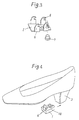
- Fig. 1 is a sectional view of a heel portion of a high heel shoe constructed according to an embodiment of the present invention as defined by claim 2 of the claim clause
- Fig. 2 is a perspective view which shows by way of example the structure of a conventional high heel shoe
- Fig. 3 is a perspective view which shows the structure of an anchor plate for the high heel shoe
- Fig. 4 is a perspective view which shows the high heel shoe constructed to the embodiment of the present invention as defined by claim 2 of the claim clause
- Fig. 5 is a perspective view which shows, in the disassembled state, essential components constituting the heel portion of the high heel shoe constructed according to the embodiment of the present invention as defined by claim 2 of the claim clause
- Fig. 1 is a sectional view of a heel portion of a high heel shoe constructed according to an embodiment of the present invention as defined by claim 2 of the claim clause
- Fig. 2 is a perspective view which shows by way of example the structure of a conventional high heel shoe
- Fig. 3 is a perspective view which shows
- FIG. 6 is an exploded plan view of the heel portion of the high heel shoe constructed according to the embodiment of the present invention as defined by claim 2 of the claim clause
- Fig. 7 is a fragmentary sectional view of a heel portion of a high heel shoe constructed according to an embodiment of the present invention as defined by claim 4 of the claim clause
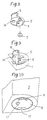
- Fig. 8 is a perspective view of an anchor plate for the high heel shoe constructed according to the embodiment of the present invention as defined by claim 4 of the claim clause
- Fig. 9 is a perspective view of a lift for the high heel shoe constructed according to the embodiment of the present invention as defined by claim 4 of the claim clause
- Fig. 10 is a perspective view of the lower end part of a heel for the high heel shoe constructed according to the embodiment of the present invention as defined by claim 4 of the claim clause
- Fig. 11 is a perspective view which shows, in the disassembled state, essential components constituting a heel portion for the high heel shoe constructed according to the embodiment of the present invention as defined by claim 4 of the claim clause
- Fig. 12 is a sectional view which shows the structure of a pin-shaped sleeve for the high heel shoe constructed according to the embodiment of the present invention as defined by claim 4 of the claim clause
- Fig. 11 is a perspective view which shows, in the disassembled state, essential components constituting a heel portion for the high heel shoe constructed according to the embodiment of the present invention as defined by claim 4 of the claim clause
- Fig. 12 is a sectional view which shows the structure of a pin-shaped sleeve for the high heel shoe constructed according to the embodiment of the present invention as defined by claim 4 of the claim clause
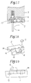
- FIG. 13 is a partially exploded sectional view of the pin-shaped sleeve constructed according to the embodiment of the present invention as defined by claim 4 of the claim clause, particularly showing a process of preventing a locking pin from being disconnected from the pin-shaped sleeve
- Fig. 14 is a sectional view of the pin-shaped sleeve for the high heel shoe constructed according to the embodiment of the present invention as defined by claim 4 of the claim clause, particularly showing that the pin-shaped sleeve is subjected to press working for the purpose of preventing the locking pin from being disconnected from the pin-shaped sleeve
- Fig. 15 is a bottom view of a heel and a lift for the high heel shoe constructed according to the embodiment of the present invention as defined by claim 4 of the claim clause, particularly showing the angular positional relationship between the heel and the lift located at the insertion/detachment position before hook-shaped engagement projections on the lift are engaged with an engagement plate on the lower end surface of the heel
- Fig. 16 is a bottom view of the heel and the lift for the high heel shoe constructed according to the embodiment of the present invention as defined by claim 4 of the claim clause, particularly showing the angular positional relationship between the heel and the lift at the attachment position where the hook-shaped engagement projections have been engaged with the engagement plate
- Fig. 17 is a sectional view of a heel portion for the high heel shoe similar to Fig.
- Fig. 18 is a perspective view of an anchor plate for a high heel shoe constructed according to an embodiment of the present invention as defined by claim 6 of the claim clause
- Fig. 19 is a side view of a lift for the high heel shoe constructed according to the embodiment of the present invention as defined by claim 6 of the claim clause
- Fig. 20 is a perspective view of a heel for the high heel shoe constructed according to the embodiment of the present invention, particularly showing, in the disassembled state, essential components constituting the heel portion
- Fig. 18 is a perspective view of an anchor plate for a high heel shoe constructed according to an embodiment of the present invention as defined by claim 6 of the claim clause
- Fig. 19 is a side view of a lift for the high heel shoe constructed according to the embodiment of the present invention as defined by claim 6 of the claim clause
- Fig. 20 is a perspective view of a heel for the high heel shoe constructed according to the embodiment of the present invention, particularly showing, in the disassembled state, essential components constituting the heel portion
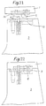
- Fig. 21 is a side view of the high heel shoe constructed according to the embodiment of the present invention as defined by claim 6 of the claim clause, particularly showing the positional relationship between the heel and the lift
- Fig. 22 is a side view of a heel portion for the high heel shoe constructed according to the embodiment of the present invention as defined by claim 6 of the claim clause
- Fig. 23 is a rear view of the heel portion for the high heel shoe constructed according to the embodiment of the present invention as defined by claim 6 of the claim clause
- Fig. 24 is an illustrative view which shows the relationship between a hook-shaped engagement projection and an engagement hole for a high heel shoe constructed according to a modified embodiment of the present invention as defined by claim 1, claim 2, claim 5 and claim 6 of the claim clause.
- reference numeral 5 designates an anchor plate.
- the anchor plate 5 includes plural pairs of hook-shaped projections 6 (four hook-shaped projections in the shown embodiment) each of which is integrated with the anchor plate 5 in the bent state while standing upright along the longitudinally extending opposite side edges of the anchor plate 5 to serve as an engagement projection.
- the anchor plate 5 is made of a metallic material plate, e.g., a stainless steel plate.
- a stepped pin-shaped signal piece 7 is secured to the lower surface of the anchor plate 5 at the rear end of the same.
- the signal piece 7 is molded of a synthetic resin, e.g., a polyurethane resin which is the same material as that of a heel 3 but has a color different from that of the lift 1.
- the anchor plate 5 is prepared in the above-described manner, it is embedded in the upper part of the lift 1 while extending substantially in parallel with the upper surface of the anchor plate 5, as shown in Fig. 1.
- an engagement plate 8 extending substantially in parallel with the upper surface of the lift 1 is secured to the lower end surface of the heel 3 (the upper end surface of the same as seen in Fig. 5 and Fig. 6) located opposite to the upper surface of the lift 1.
- the engagement plate 8 is made of a rectangular metallic material plate having two longitudinally extending cutouts formed along each side edge thereof.
- Each of the cutouts serves as a kind of engagement hole as mentioned above.
- a stopper hole 8a through which the lower end part of a locking pin 11 to be described later is inserted as well as a fixing shaft hole 8b through which a fixing shaft 9 is inserted are drilled through the central part of the engagement plate 8. It is obvious that the stopper hole 8a is located at the intersection where a locking pin 11 to be described later intersects the engagement plate 8.
- the lower surface of the heel 3 (the upper surface of the same as seen in Fig. 5) has a recess formed therein, and a part of the recess having a smallest depth is contoured in the form of an elongated rectangular mounting platform 3a.
- a fixing shaft hole 3b and a pin hole 3c are formed in the mounting platform 3a, and they are located in alignment with each other in the longitudinal direction.
- a fixing shaft 19 having a number of slantwise knurled portions 19a formed therearound is press-fitted through the fixing shaft hole 8a into the fixing shaft hole 3b by actuating a certain tool, e.g., a wood hammer with an operator's hand so as to impart a high intensity of striking force to the flange-shaped head portion of the fixing shaft 19.
- a certain tool e.g., a wood hammer with an operator's hand
- the heel 3 is usually molded of a synthetic resin such as acrylonitrile-butadiene-styrene copolymer
- the inner diameter of the fixing shaft hole 3b is temporarily enlarged due to elastic deformation of the heel 3.
- the inner cylindrical portion of the fixing shaft hole 3b restores the original inner diameter, whereby the fixing shaft 9 is immovably held by the frictional engagement of the slantwise knurled portions 9a with the fixing shaft hole 3b.
- the locking pin 11 and a pin spring 12 serving as a compression spring for biasing the locking pin 11 in the downward direction are preliminarily received in the pin hole 3c before the engagement plate 8 is fixedly secured to the heel 3 with the aid of the fixing shaft 19.
- the locking pin 11 is designed in the form of a stepped pin of which larger diameter portion has a cylindrical hollow space in which the pin spring 12 is received.
- peripheral edge located outside of the mounting platform 3a of the heel 3 is recessed to be deeper than the surface of the mounting platform 3a (i.e., downward of the surface of the mounting platform 3a as seen in Fig. 5).
- the engagement plate 8 is fixedly secured to the heel 3 at the position above the lower end surface of the heel 3.
- the engagement plate 8 is fixedly secured to the heel 3 at the position dislocated upward of the lower surface of the heel 3 so as to avoid the aforementioned interference.
- the engagement plate 8 is fixedly secured to the heel 3 using flat head screws (not shown) so as to enable the lower surface of the engagement plate 8 to be flush with the lower surface of the heel 3.
- the pin hole 1a on the lift 1 side is formed on the upper surface of the lift 1 at the insertion/detachment position where it is correctly aligned with the pin hole 3c when the lift 1 is fixedly secured to the heel 3 as shown in Fig. 1.
- a depth of the pin hole 1a on the lift 1 side is dimensioned such that it extends in the downward direction at least through the anchor plate 5 (see Fig. 1).
- the fact that there is no possibility that the lift 1 is disconnected from the heel 3 represents that the lift 1 can not be disconnected from the heel 3 for a certain period of time after completion of the fitting operation.
- a rod having a small diameter is inserted into the pin hole 1a through the exposed end of the lift 1 so as to raise up the locking pin 11 until the locking pin 11 is released from the engaged state relative to the lift 1.
- the worn lift 1 is ready to be easily disconnected or removed from the heel 3.
- reference numeral 5 designates an anchor plate which is constructed according to the invention as defined by claim 4 of the claim clause.
- the anchor plate 5 is shown in the form of a bottom plate for a cylindrical cup, and two hook-shaped engagement projections 6 each standing upright along a part of the outer peripheral surface of the cylindrical cup are integrated with the anchor plate 5.
- the anchor plate 5 is made of a metallic material plate, e.g., a stainless steel plate.
- reference numeral 7 designates a signal piece which is coincident with the signal piece constructed according to the invention as defined by claim 2 of the claim clause. Thus, repeated description on the signal piece 7 will not be required.
- the anchor plate 5 constructed in the above-described manner is embedded in the upper part of the lift 1 while extending substantially in parallel with the upper surface of the lift 1, whereby at least one hook-shaped engagement projection 6 (two hook-shaped engagement projections in the shown embodiment) is projected upward of the upper surface of the lift 1 as shown in Fig. 9.
- an engagement plate 8 is secured to the lower end of the heel 3 while extending substantially in parallel with the upper surface of the lift 1.
- the engagement plate 8 is designed in the form of a circular metallic plate having two arc-shaped cutouts 13 symmetrically formed along the outer periphery thereof.
- the arc-shaped cutouts 13 correspond to the engagement holes in the preceding embodiment.
- the lower end surface of the heel 3 is recessed in the form of a circular cavity so that the engagement plate 8 is mounted on a mounting surface 3a corresponding to the bottom of the circular cavity so as to allow it to be secured to the heel 3 with the aid of a pin-shaped sleeve 9 to be described later.
- a part of the mounting surface 3a is recessed to be deeper than the level of the mounting surface 3a at the positions exactly corresponding to the cutouts 13 of the engagement plate 8 in the same manner as the preceding embodiment.
- a pin-shaped sleeve hole 3b is formed on the mounting surface 3a of the heel 3 at the position offset from the center line of the heel 3, and a chamfered sleeve hole 8b is formed on the engagement plate 8 at the position located in alignment with the pin-shaped sleeve hole 3b.
- the pin-shaped sleeve 9, of which upper end is kept closed and of which lower end is slantwise expanded to form a truncated-conical flange, is caused to pass through the chamfered sleeve hole 8b of the engagement plate 8, and thereafter, the upper end part of the pin-shaped sleeve 9 is press-fitted into the pin-shaped sleeve hole 3b, whereby the engagement plate 8 is fixedly secured to the lower end part of a heel 3 (see Fig. 10).
- pin-shaped sleeve 9 is stably fixed to the heel 3 for a long time, it is recommendable that the pin-shaped sleeve 9 and the pin-shaped sleeve hole 3b are coated with an adhesive.
- a pin spring 12 serving as a compression spring and a stepped locking pin 11 are received in the pin-shaped sleeve 9.
- annular projection 9b having a truncated conical sectional shape is formed around the opening edge of the pin-shaped sleeve 9 as shown in Fig. 12.
- the annular projection 9b is forcibly press-deformed by actuating a press jig 10 so as to form an annular inner projection along the opening edge of the pin-shaped sleeve 9, as shown in Fig. 13.
- the annular projection 9b is deformed in the inward direction to form an annular inner projection along the opening edge of the pin-shaped sleeve 9 so that the stepped part of the locking pin 11 is engaged with the annular inner projection so as to prevent the locking pin 11 from being disconnected from the pin-shaped sleeve 9, as shown in Fig. 14. It is obvious that the press working to be performed using the press jig 10 is achieved before the pin-shaped sleeve 9 is press-fitted into the pin-shaped sleeve hole 3b (see Fig. 11).
- the pin-shaped sleeve hole 3b on the heel 3 side serves as an inner cylindrical portion for the pin-shaped sleeve 9.
- a pin hole 1a is formed on the upper surface of a lift 1 at the position which is located in alignment with the locking pin 11 when the lift 1 is secured to the heel 3.
- the pin hole 1a has a large depth enough to allow the locking pin 11 to pass through the anchor plate 5 (see Fig. 8).
- the engagement projections 16 are located in alignment with the engagement holes 13 on the engagement plate 8 but the pin hole 1a on the lift 1 side is not located in alignment with the locking pin 11 adapted to be projected downward of the lower end surface of the heel 3.
- the hook-shaped engagement projections 6 on the anchor plate 5 can be inserted into the engagement holes 13 on the engagement plate 8 while the locking pin 11 is retracted in the heel 3 by the upper surface of the lift 1.
- the lift 1 When the lift 1 is turned toward the attachment position in the arrow-marked direction as seen in Fig. 15 while the foregoing state is maintained, the horizontal portions of the hook-shaped engagement projections 6 are brought in engagement with the upper surface of the engagement plate 8, and at the same time, the locking pin 11 is located in alignment with the pin insert hole 1a on the lift 1 side.
- the lift 1 can fixedly be secured to the heel 3 without any possibility that the lift 1 is disconnected from the heel 3 in the same manner as the preceding embodiment.
- Fig. 18 to Fig. 23 show an embodiment of the present invention as defined by claim 6 of the claim clause.
- Fig. 18 shows by way of perspective view the structure of an anchor plate.
- the anchor plate 5 is constructed such that a substantially rectangular metallic plate is bent along the opposite side edges in the U-shaped sectional contour to form a pair of first rail portions 14 extending in parallel with each other on the upper surface (the lower surface as seen in Fig. 18) of the anchor plate 5, and the central part of the anchor plate 5 is bent toward the first rail portions 14 to form a hook-shaped engagement projection 6. It is desirable that the anchor plate 5 is made of a metallic material plate, e.g., a stainless steel plate.
- a fitting hole is formed at the rear end (the right-hand end as seen in Fig. 18) of the anchor plate 5, and a signal piece 7 is press-fitted through the fitting hole from below in the same manner as the anchor plate shown in Fig. 8.
- the anchor plate 5 constructed in the above-described manner is embedded in a lift 1 while extending substantially in parallel with the upper surface of the lift 1, wherein a pair of first rail portions 14 and a hook-shaped engagement projection 6 are projected upward of the upper surface of the lift 1.
- a pin hole 1a is formed through the anchor plate 5 on the upper surface side of the lift 1.
- the pin hole 1a is dimensioned to have a large depth enough to enable a locking pin 11 to pass through the anchor plate 5.
- an engagement plate 8 is secured to the lower end surface (the upper end surface as seen in Fig. 20 and Fig. 21) of the heel 3 while extending substantially in parallel with the upper surface of the lift 1.
- the engagement plate 8 is made of a metallic material plate such that the opposite edges of the metallic material plate are bent in the U-shaped sectional contour to form a pair of second rail portions 15.
- a rectangular engagement hole 13, a stopper hole 8a through which the lower end of the locking pin 11 is caused to pass, and a fixing shaft hole 8b through which a fixing shaft 19 is caused to pass are formed along the central part of the engagement plate 8 in accordance with the order as seen from the rear side (the right-hand side as seen in Fig. 20). It is obvious that the stopper hole 8a serves as an intersection where the pin hole 1a intersects the engagement plate 8.
- the lower surface (the upper surface as seen in Fig. 20) of the heel 3 is recessed in the rectangular contour to form a mounting surface 3a at the bottom of the rectangular cavity.
- a part of the mounting platform 3a corresponding to a rectangular engagement hole 13 on the engagement plate 8 is recessed to have a large depth, while a pin hole 3c and a fixing shaft hole 3b are formed on the mounting platform 3a at the positions located in alignment with the stopper hole 8a and the fixing shaft hole 8b on the engagement plate 8.
- a fixing shaft 9 having a number of slantwise knurled portions 19a formed therearound is used in the same manner as the embodiment of the present invention as defined by claim 2 of the claim clause.
- a locking pin 11 and a pin spring 12 serving as a compression spring for biasing the locking pin 11 in the downward direction are preliminarily received in the pin hole 3c on the heel 3 side before the engagement pin 8 is fixed to the heel 3 with the aid of the fixing shaft 9.
- the locking pin 11 is designed in the form of a stepped pin including a cylindrical larger diameter sleeve portion in which a pin spring 12 is received.
- the distance between the pair of first rail portions 14, the distance between the pair of second rail portions 15 and the relative positional relationship between the first rail portions 14 and the second rail portions 15 are determined in such a manner that when the lift 1 is secured to the heel 3 as shown in Fig. 23, the first rail portions 14 are held in the second rail portions 14 in the clamped state while maintaining a gap of, e.g., about 0.03 mm therebetween.
- the engagement projection 6 is displaced in the horizontal direction.
- the hook-shaped engagement projections 6 may be displaced in the transverse direction as shown in Fig. 24. In this case, a quantity of displacement required by the hook-shaped engagement projection 6 can be reduced but there arises a necessity for modifying the contour of the engagement hole 13 to a L-shaped one.
- a worn lift can easily and simply be exchanged with a new one by an unskilled operator.
- the present invention can equally be applied to all the kinds of shoes with advantageous effects.
Landscapes
- Footwear And Its Accessory, Manufacturing Method And Apparatuses (AREA)
Abstract
L'invention se rapporte à une structure de talon de chaussure et, plus particulièrement, à une chaussure pourvue d'un bon-bout qui peut être remplacé facilement et simplement. A cet effet, des saillies en forme de crochets (6) sont prévues sur la partie supérieure du bon-bout et, en outre, une plaque de prise (8), fixée à la surface terminale inférieure du talon, comporte des trous (13) dans lesquels s'engagent les saillies (6) lors de tout mouvement ou de toute rotation du bon-bout par rapport au talon, pour que l'interpénétration entre les saillies et la plaque de prise (8) puisse bloquer à la fois le bon-bout et le talon contre tout mouvement vertical, et, de plus, un goujon de blocage (11), amené à agir dans la direction d'approche du bon-bout, est placé dans un trou traversant le talon et le bon-bout lorsque ce dernier est fixé au talon, afin de bloquer le bon-bout et le talon contre tout mouvement horizontal.
Applications Claiming Priority (5)
| Application Number | Priority Date | Filing Date | Title |
|---|---|---|---|
| JP288215/91 | 1991-08-15 | ||
| JP28821591 | 1991-08-15 | ||
| JP4035515A JPH0761281B2 (ja) | 1991-08-15 | 1992-01-06 | リフトを交換できるハイヒールなどの靴類 |
| JP35515/92 | 1992-01-06 | ||
| JP4221892A JPH0646905A (ja) | 1992-07-28 | 1992-07-28 | リフトを交換できるハイヒールなどの靴類 |
Publications (2)
| Publication Number | Publication Date |
|---|---|
| EP0594855A4 EP0594855A4 (fr) | 1993-12-16 |
| EP0594855A1 true EP0594855A1 (fr) | 1994-05-04 |
Family
ID=27288786
Family Applications (1)
| Application Number | Title | Priority Date | Filing Date |
|---|---|---|---|
| EP92916807A Withdrawn EP0594855A1 (fr) | 1991-08-15 | 1992-08-07 | Chaussure avec bon-bout rempla able |
Country Status (3)
| Country | Link |
|---|---|
| EP (1) | EP0594855A1 (fr) |
| CA (1) | CA2093118A1 (fr) |
| WO (1) | WO1993003640A1 (fr) |
Cited By (1)
| Publication number | Priority date | Publication date | Assignee | Title |
|---|---|---|---|---|
| GB2294628A (en) * | 1994-11-05 | 1996-05-08 | Agentdraw Ltd | Heel top piece |
Families Citing this family (2)
| Publication number | Priority date | Publication date | Assignee | Title |
|---|---|---|---|---|
| US20170347750A1 (en) * | 2014-11-13 | 2017-12-07 | Kelteknohow Limited | An article of wear |
| CN111329182B (zh) * | 2020-03-12 | 2021-09-24 | 浙江理工大学 | 一种高度可调的高跟鞋 |
Family Cites Families (8)
| Publication number | Priority date | Publication date | Assignee | Title |
|---|---|---|---|---|
| US2206898A (en) * | 1937-04-14 | 1940-07-09 | Hugo R Hustad | Heel structure of footwear |
| US3063169A (en) * | 1961-05-12 | 1962-11-13 | Cortina Anthony | Detachable rubber shoe heel |
| JPS4924447U (fr) * | 1972-06-06 | 1974-03-01 | ||
| US3797136A (en) * | 1973-06-25 | 1974-03-19 | R Soleri | Shoe with flexible height adjustment sole and assorted heights interchangeable heels |
| JPS58196604U (ja) * | 1982-06-23 | 1983-12-27 | 藤原 利一 | 靴の踵 |
| JPS60167513U (ja) * | 1984-04-17 | 1985-11-07 | 山田株式会社 | 靴、サンダル等履物 |
| JPS6326007Y2 (fr) * | 1985-04-10 | 1988-07-15 | ||
| US4667421A (en) * | 1986-04-28 | 1987-05-26 | Rouhani S Zia | Detachable heel for shoes and boots |
-
1992
- 1992-08-07 EP EP92916807A patent/EP0594855A1/fr not_active Withdrawn
- 1992-08-07 CA CA 2093118 patent/CA2093118A1/fr not_active Abandoned
- 1992-08-07 WO PCT/JP1992/001019 patent/WO1993003640A1/fr not_active Ceased
Cited By (2)
| Publication number | Priority date | Publication date | Assignee | Title |
|---|---|---|---|---|
| GB2294628A (en) * | 1994-11-05 | 1996-05-08 | Agentdraw Ltd | Heel top piece |
| GB2294628B (en) * | 1994-11-05 | 1998-07-01 | Agentdraw Ltd | Top piece |
Also Published As
| Publication number | Publication date |
|---|---|
| CA2093118A1 (fr) | 1993-02-16 |
| EP0594855A4 (fr) | 1993-12-16 |
| WO1993003640A1 (fr) | 1993-03-04 |
Similar Documents
| Publication | Publication Date | Title |
|---|---|---|
| US4436238A (en) | Apparatus for attaching fastener elements onto a garment | |
| US7891275B2 (en) | Adapter coupling device | |
| US5108442A (en) | Prosthetic implant locking assembly | |
| US5361925A (en) | Terminal box | |
| US4977660A (en) | Tool for removing and installing an automotive universal joint | |
| US5903331A (en) | Eyeglasses comprising frame unit and snap fitted lens unit | |
| NZ527973A (en) | Eyewear with interchangable temples | |
| US20030110907A1 (en) | Wrench extension with a socket-coupling system | |
| US20140056663A1 (en) | Fastener | |
| GB2183715A (en) | An improved belt buckle | |
| US6655049B2 (en) | Connector for attaching and detaching attachment to/from shoe sole | |
| EP1682312B1 (fr) | Procede et appareil pour ensemble de fixation ayant un element elastique de raccordement a un outil | |
| EP0092408A2 (fr) | Boucle d'oreille et sa pince | |
| EP0300660B1 (fr) | Emerillon | |
| EP0596520A1 (fr) | Ejecteur automatique monté dans le cadre d'un pistolet et interconnecté avec le pirot de chier | |
| EP1331027A1 (fr) | Patin avec chaussure détachable | |
| AU661676B2 (en) | Snap fastener and tooling therefor | |
| US4586641A (en) | Apparatus for attaching pairs of fastener elements onto garment fabrics | |
| KR101350031B1 (ko) | 자동차 매트 후크 | |
| US3964660A (en) | Snap attaching tool | |
| JPH0761281B2 (ja) | リフトを交換できるハイヒールなどの靴類 | |
| CA2093118A1 (fr) | Soulier comportant un talon remplacable | |
| EP0469668A1 (fr) | Assemblage pour pieds de meubles | |
| US5917575A (en) | Split rim eyeglass frame mounting | |
| KR200177132Y1 (ko) | 안경다리 탄착장치의 변형 방지법 |
Legal Events
| Date | Code | Title | Description |
|---|---|---|---|
| PUAI | Public reference made under article 153(3) epc to a published international application that has entered the european phase |
Free format text: ORIGINAL CODE: 0009012 |
|
| 17P | Request for examination filed |
Effective date: 19930510 |
|
| AK | Designated contracting states |
Kind code of ref document: A1 Designated state(s): DE FR GB IT |
|
| 18D | Application deemed to be withdrawn |
Effective date: 19960301 |