EP0594895A1 - Appareil de traitement photographique - Google Patents
Appareil de traitement photographique Download PDFInfo
- Publication number
- EP0594895A1 EP0594895A1 EP92203312A EP92203312A EP0594895A1 EP 0594895 A1 EP0594895 A1 EP 0594895A1 EP 92203312 A EP92203312 A EP 92203312A EP 92203312 A EP92203312 A EP 92203312A EP 0594895 A1 EP0594895 A1 EP 0594895A1
- Authority
- EP
- European Patent Office
- Prior art keywords
- roller
- rollers
- actuator
- cam
- output rod
- Prior art date
- Legal status (The legal status is an assumption and is not a legal conclusion. Google has not performed a legal analysis and makes no representation as to the accuracy of the status listed.)
- Granted
Links
Images



Classifications
-
- G—PHYSICS
- G03—PHOTOGRAPHY; CINEMATOGRAPHY; ANALOGOUS TECHNIQUES USING WAVES OTHER THAN OPTICAL WAVES; ELECTROGRAPHY; HOLOGRAPHY
- G03D—APPARATUS FOR PROCESSING EXPOSED PHOTOGRAPHIC MATERIALS; ACCESSORIES THEREFOR
- G03D3/00—Liquid processing apparatus involving immersion; Washing apparatus involving immersion
- G03D3/08—Liquid processing apparatus involving immersion; Washing apparatus involving immersion having progressive mechanical movement of exposed material
- G03D3/13—Liquid processing apparatus involving immersion; Washing apparatus involving immersion having progressive mechanical movement of exposed material for long films or prints in the shape of strips, e.g. fed by roller assembly
- G03D3/132—Liquid processing apparatus involving immersion; Washing apparatus involving immersion having progressive mechanical movement of exposed material for long films or prints in the shape of strips, e.g. fed by roller assembly fed by roller assembly
-
- G—PHYSICS
- G03—PHOTOGRAPHY; CINEMATOGRAPHY; ANALOGOUS TECHNIQUES USING WAVES OTHER THAN OPTICAL WAVES; ELECTROGRAPHY; HOLOGRAPHY
- G03D—APPARATUS FOR PROCESSING EXPOSED PHOTOGRAPHIC MATERIALS; ACCESSORIES THEREFOR
- G03D15/00—Apparatus for treating processed material
- G03D15/02—Drying; Glazing
-
- G—PHYSICS
- G03—PHOTOGRAPHY; CINEMATOGRAPHY; ANALOGOUS TECHNIQUES USING WAVES OTHER THAN OPTICAL WAVES; ELECTROGRAPHY; HOLOGRAPHY
- G03F—PHOTOMECHANICAL PRODUCTION OF TEXTURED OR PATTERNED SURFACES, e.g. FOR PRINTING, FOR PROCESSING OF SEMICONDUCTOR DEVICES; MATERIALS THEREFOR; ORIGINALS THEREFOR; APPARATUS SPECIALLY ADAPTED THEREFOR
- G03F7/00—Photomechanical, e.g. photolithographic, production of textured or patterned surfaces, e.g. printing surfaces; Materials therefor, e.g. comprising photoresists; Apparatus specially adapted therefor
- G03F7/26—Processing photosensitive materials; Apparatus therefor
- G03F7/30—Imagewise removal using liquid means
- G03F7/3042—Imagewise removal using liquid means from printing plates transported horizontally through the processing stations
Definitions
- This invention relates to apparatus for the processing of photographic sheet materials and particularly for developing exposed photographic material, and more particularly to apparatus for developing lithographic offset printing plates.
- a good removal of processing liquid is also required to reduce the drying time of the sheet material after the last process bath, and hence reduce energy use.
- rollers In order to obtain good imaging quality it is necessary for the rollers to exert a load in the order of 0.5 - 6.0 N/cm roller length to remove excess materials. To this end the rollers are biased together typically by springs which act on the ends of the roller shafts.
- the roller can become coated with gelatin and if the apparatus is switched off with the rollers stationary and biased together then after several hours the rollers become glued together by the gelatin. As a result of this the roller surfaces may become damaged, and the drive gears may also be damaged when the apparatus is restarted.
- rollers have an elastomeric surface, if the apparatus is left with the squeeze rollers biased together, the rollers may take on a set and become temporarily deformed and when the apparatus is restarted this may result in poor quality image reproduction for the first few plates processed on the re-start, after which the deformation disappears.
- the present invention seeks to provide a solution to the above problem of rollers adhering together when the apparatus is idle.
- an apparatus for processing photographic sheet material including at least two rollers rotatable on respective shafts and which are biased together, characterized in that there is provided at each end of at least one roller shaft, a moving means operably connected with said one roller shaft for relative movement of said one roller away from the other roller to open the rollers.
- the moving means comprise a first cam means at each end of said one roller shaft that co-operate with second cam means at each end of said other roller shaft.
- the second cam means may comprise a circular cam fixed to said other roller shaft and the first cam means comprises an eccentric cam which is connected to said one roller shaft through a one way clutch so that in one direction of rotation of said one roller the eccentric cam is free to rotate relative to said one roller, and in the other direction of rotation the eccentric can is rotationally fast with said roller, so that rotation of the eccentric cam in said other direction of rotation causes the one roller to move away from the other roller.
- the moving means is a fluid powered actuator having a reciprocable output rod which is pivotally connected to a bar linkage mechanism which is operable by one direction of movement of the output rod to move said one roller away from the other roller.
- the bar linkage mechanism comprises a first link pivotally connected at one end by a first pivot to the actuator output shaft and pivotally connected by a second pivot to one end of a second link which is in turn connected by a third pivot fixed relative to the axis of rotation of said one roller, the second link having a cranked end portion extending away from the third pivot which in use is engagable with said one roller shaft to move said one roller away from the other roller during said one direction of movement of the actuator shaft.
- the two rollers may be squeeze rollers and the apparatus may further include a third pressure roller which is utilized to bias an upper squeeze roller against a lower squeeze roller, and the actuator output shaft is pivotally connected to a second bar linkage mechanism which is also operable in said one direction of movement of the actuator shaft to lift the third roller away from the upper squeeze roller.
- FIG. 1 With reference to fig. 1 there is illustrated a longitudinal cross-section through an apparatus 10 for processing exposed photographic sheet material, in particular aluminium lithographic printing plates, of the type described in EP-A-410500.
- EP-A-410500 disclosed an imaging element containing an aluminium support provided with in the order given an image receiving layer and a silver halide emulsion.
- a diffusion transfer reversal process (hereinafter called DTR-process) for obtaining a lithographic printing plate in which said imaging element is image-wise exposed and subsequently developed using a developing liquid or activating liquid in the presence of a silver halide complexing agent.
- the imaging element is then guided through a diffusion transfer zone so that the silver halide complexes formed during the development step are allowed to diffuse into the image-receiving layer where they are converted to silver.
- the imaging element leaves the diffusion transfer zone a silver image is formed in the image receiving layer.
- the now useless photosensitive layer and optional other layers above the image receiving layer are then removed by rinsing the imaging element in a washing section.
- the element now carrying a silver image on its surface is treated with a finishing liquid that contains so called hydrophobizing agent for improving the hydrophobicity of the silver image.
- At least three different liquids are used i.e. a developing or activating liquid, a rinsing liquid and a finishing liquid.
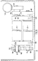
- the apparatus 10 is mounted within a generally rectangular housing 22 (Figs. 2 & 3) which may include a rectangular metal frame (not shown) for supporting the various parts of the apparatus.
- the apparatus comprises a sheet feed means 11, preferably a pair of rollers, a developing section 12, a diffusion transfer section 13, a wash section 14, a rinse section 15, a finishing section 16, a drier 17, and output rollers 18.
- All these sections include conveyor rollers 20 and the exit ends of the developing section 12, wash section 14 and the finishing section 16 have sets of squeeze rollers 21 to remove excess liquid from the sheet material as it exits the respective section. Sets of squeeze roller 21 may also be used in the rinse sections.
- rollers 11, 20, 21, 18 and squeeze rollers are linked by a single drive shaft 26 (see Figs. 4 & 5) to operate simultaneously to advance sheet material through the apparatus 10 from the feed means 11 to the output rollers 18.
- Each set of squeeze rollers 21 comprises a lower squeeze roller 23, and upper squeeze roller 24, which are fixed on respective shafts 31 and 32 for rotation.
- the lower squeeze roller shaft 31 is driven at one end thereof through gears 27, 28, by the drive shaft 26, and the upper squeeze roller shaft 32 is driven by gear 29 that meshes with the gear 28 for operation of the set of squeeze rollers 21.
- gear 29 that meshes with the gear 28 for operation of the set of squeeze rollers 21.
- the end portions of the rotation shafts 31, 32 are located within end bearings 34, as best seen in Figs. 2 and 3 which show the ends of the shafts away from the gear drive.
- the end bearings 34 are formed from a suitable polymer material such as nylon or acetal resin each have a hexagonal end cap 35 to allow them to slide within a retaining groove or slot 43, 44 whilst preventing the rotation of the bearings 34 in the slots.
- the lower squeeze roller 23 is held by the end bearings 34 on its shaft 31 in a pair of opposed slots 43 with an open upper end to allow easy removal of the lower squeeze roller.
- the upper squeeze roller 24 is held by the end bearings 34 on its shaft 32 in the second pair of opposed slots 44 which hold the upper squeeze roller 24 firmly in alignment with the lower roller 23 but allows the upper roller 24 to move towards and away from the lower squeeze roller.
- the axis of rotation of the two squeeze rollers 23 and 24, respectively, may be off-set by a small angle from the vertical towards the feed side of the rollers so that if necessary the rollers 23, 24 are arranged in a line normal to an inclined feed surface, and the opposed slots 44 may be inclined to achieve this end.
- the upper ends of the slots 44 are open to facilitate the removel of the upper roller 24.
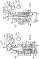
- the upper roller 24 is biased towards the lower roller 23 by two arms 50, operated by actuators 53, and each of which acts against the upper shaft end bearing 34 to bias the upper squeeze roller towards the lower squeeze roller (see Fig. 3).
- Each arm 50 is part of bar linkage mechanism and forms part of a first link 54 one end of which is connected by a first pivot pin 55 to the output rod 52 of a pneumatic single stroke actuator 53.
- the first link 54 is connected by a second pivot pin 56, longitudinally spaced from the first pivot pin 55, to one end of a second link 57.
- the second link 57 is connected by a third pivot pin 58 spaced from the second pivot pin 55.
- the third pivot pin 58 is fixed to a support 59 which is attached to flanged end fitting 64.
- the second link 57 has a cranked over end portion 60 extending away from the fixed pivot 58 which forms a cradle for lifting the respective roller end bearing 34.
- the first link 54 can be formed from two parallel arms of a folded strip of sheet metal, and the second link 57 can also be formed from two aligned sheet metal parts.
- the cranked end portion 60 of the second hub 57 can also be formed separately from the rest of the second link, and arranged to be rotationally fast therewith in the lifting direction.
- the actuator 53 has a cylindrical body 61 with a first end plate 62 at one end thereof having a screw threaded coaxial spigot 63 thereon through which the output rod 52 slidingly passes, and a second end plate 68 at the other end thereof.
- the spigot 63 engages a like threaded flanged end fitting 64 so that the actuator is attached to the housing 22 by the spigot 63 engaging in a hole 25 in the housing 22 and the end fitting 64 screwed thereon to trap a portion of the housing 22 between the end fitting of the first end plate 62.
- the support 59 is integrally formed as a part of the end fitting 64.
- the output rod 52 slidably passes through the end fitting 64 and is sealed thereto by a seal 65.
- the rod 52 is coaxial with the body 61 and is fixed to a piston assembly 66 which is sealingly reciprocable within the body 61.
- the piston diameter is about 40 mm diameter to give a squeeze load as required for the rollers.
- a fluid port 67 is located in the other end plate 68 for the ingress and egress of actuating fluid.
- the piston assembly 66 is biased away from the first end plate 62, by a coaxial spring 71 acting therebetween and arranged concentrically around the piston assembly 66.
- the spring 71 has to exert sufficient spring load to lift the respective end portion of the upper roller 24.
- the spring 71 has a very low spring constant and is held under a pre-load.
- the actuator 53 is a pneumatic actuator and in the present example air at a pressure of 3 bar is introduced into the actuator through the fluid port 67 and moves the piston assembly into abutment with the first end plate 62 at which position the actuator rod 52 has moved the pivot pin 55 causing the bar linkage mechanism to pivot about the pivots 56 and 58 and thereby bring the arm 50 into contact with the respective bearing end cap 34 to bias the upper roller 24 towards the lower roller 23, as shown in Fig. 7.
- the piston assembly 66 comprises a piston body 72 having a coaxial cylindrical tube 73 which is guided for movement in an opposing sleeve 74 forming part of the first end plate 62.
- the piston body is fixed to the output rod 52 by a screw threaded portion 75 of the rod which co-operates with a nut 76.
- the piston body tube 73 bottoms out on the end plate 62 at the end of the piston stroke.
- the piston assembly is adjusted so that the arm 50 contacts the respective end bearings 34 with the piston body 73 about 3 mm from the end of the stroke. The piston then moves to exert a load on the upper roller 24.
- a second spring 77 concentric with the rod 52 acts between a spring end cap 78, which locates on a shoulder 79 on the rod 52, and the piston body 73.
- the spring helps lock the adjusted piston body 73 in position.
- the piston assembly 62 has a seal 81 located between a piston cap 82 and the piston body 73.
- the piston cap 82 screws into the piston body and is held in position by a pin 83 which locks into the nut 76.
- the actuator 53 is connected to an air reservoir 85 via a two way valve 87 and pressure regulator 88.
- the reservoir 85 is connected to an air pump 89.
- the two way valve is operated to connect the air reservoir 85 to the actuator 53 introducing air pressure into the actuator body 61 thereby moving the piston assembly 66 forward against the bias of the spring 71.
- the piston is then held at the end of its stroke loading the upper roller downwards until the air pressure is released by operating the valve 87 until it is connected to atmosphere.
- the upper roller 24 may be biased downward by a pressure roller (not shown).
- the pressure roller is held by end bearings on its shaft in a third set of opposed grooves or slots which may, if desired run into the respective second slots 44, and which also has an open upper end to allow removal of the pressure roller 25, in this case the pressure roller may also be lifted by having an additional bar linkage mechanism connected to the actuator output rod 52.
- FIG. 8 Yet another alternative arrangement for moving the upper roller 24 away from the lower roller 23 is shown in Figs. 8, 9 and 10. Where components are substantially the same as components described with reference to Figs. 2 - 7 they will be given the same reference numbers.
- the rotation shafts 31, 32 of the lower and upper rollers 23, 24 respectively have cams 101, 102 secured thereto at each end thereof.
- the cams 101 on the lower roller shaft 31 are circular and may be fixed for rotation with the shaft 31. If the lower cams 101 are made from an engineering polymer such as nylon or acetal resin then the cams 101 may be rotatable on the shaft 31 when no load is applied to the cams and will be held fixed on the shaft by friction when a load is applied to the cams 101.
- the cams 102 on the upper roller shaft 32 are eccentric, and are secured on the shaft 32 through a one way clutch or bearing mechanism 104 which allows the cams 102 to rotate relative to the shaft 32 in one direction, but locks the cams relative to the shaft 32 in the other direction of rotation (this is shown on one side of Fig. 8 only).
- the one way mechanism 104 is sealed on the shaft 23 to prevent contamination.
- the upper roller 24 is a driven roller and the lower roller 23 is an idle roller.
- the two roller shafts 31, 32 rotate in bearings 105, 106 respectively which are held in a pair of frames 107 located one at each end of the rollers.
- the upper roller 24 rotates in bearing 106 fixed in the frames 107 and is rotated by a drive gear 128 which is driven by a worm screw 126.
- the lower roller 23 rotates in its bearings 105 and the bearings 105 slide in guides 108 in the frames 107 so that the lower roller 23 is free to move towards and away from the upper roller 24 as the bearings 105 move between the positions 105a and 105b as shown in Figs. 9 and 10.
- Springs 109 bias the lower roller 23 towards the upper roller 24 by a force of up to 400 N.
- the lower roller 23 is free to move between 1 - 6 mm away from the upper roller in order to break the miniscus of any process liquid on the rollers.
- the eccentric cams 102 on the upper roller 24 are each held in an "at-rest" position during said one direction of rotation by an index clip 110 which rests against an abutment 111 on the respective frame 107.
- the roller can be made to move apart over the first 180-210 degrees of rotation of the upper cam 102 relative to the lower cam 101, be held apart at a pre-set distance for 60 degrees of rotation, and then move together over the last 120 - 90 degrees of movement.
- the frames 107 are removeable from the housing 22 so t hat the rollers 23 - 24, frames 107 etc., can be removed from the housing as a complete squeeze roller set 21.
- the frames 107 are adapted to receive handles for the removal of the squeeze roller set, the frame 107a away from the worm drive 126 being lifted first to disengage the drive gear 128 from the worm drive 126.
- the eccentric cams 102 can be made to operate simultaneously or in step wise progression whichever is desired. In the preferred embodiment the eccentric cams 102 operate simultaneously.
Landscapes
- Physics & Mathematics (AREA)
- General Physics & Mathematics (AREA)
- Photographic Processing Devices Using Wet Methods (AREA)
- Photographic Developing Apparatuses (AREA)
Priority Applications (2)
| Application Number | Priority Date | Filing Date | Title |
|---|---|---|---|
| EP19920203312 EP0594895B1 (fr) | 1992-10-28 | 1992-10-28 | Appareil de traitement photographique |
| DE1992626189 DE69226189T2 (de) | 1992-10-28 | 1992-10-28 | Photographisches Entwicklungsgerät |
Applications Claiming Priority (1)
| Application Number | Priority Date | Filing Date | Title |
|---|---|---|---|
| EP19920203312 EP0594895B1 (fr) | 1992-10-28 | 1992-10-28 | Appareil de traitement photographique |
Publications (2)
| Publication Number | Publication Date |
|---|---|
| EP0594895A1 true EP0594895A1 (fr) | 1994-05-04 |
| EP0594895B1 EP0594895B1 (fr) | 1998-07-08 |
Family
ID=8211001
Family Applications (1)
| Application Number | Title | Priority Date | Filing Date |
|---|---|---|---|
| EP19920203312 Expired - Lifetime EP0594895B1 (fr) | 1992-10-28 | 1992-10-28 | Appareil de traitement photographique |
Country Status (2)
| Country | Link |
|---|---|
| EP (1) | EP0594895B1 (fr) |
| DE (1) | DE69226189T2 (fr) |
Cited By (3)
| Publication number | Priority date | Publication date | Assignee | Title |
|---|---|---|---|---|
| EP0684524A1 (fr) * | 1994-05-25 | 1995-11-29 | Agfa-Gevaert N.V. | Procédé et dispositif pour la fabrication d'une plaque d'impression lithographique offset suivant le procédé de diffusion-transfert de sel d'argent |
| EP0789276A1 (fr) * | 1996-02-08 | 1997-08-13 | Agfa-Gevaert N.V. | Appareil pour le traitement de feuilles photographiques |
| WO1999017163A1 (fr) * | 1997-09-29 | 1999-04-08 | Eastman Kodak Company | Ensemble de rouleaux destine au transport de film |
Citations (3)
| Publication number | Priority date | Publication date | Assignee | Title |
|---|---|---|---|---|
| GB1530619A (en) * | 1975-12-19 | 1978-11-01 | Polychrome Corp | Apparatus for developing offset printing plates |
| EP0177873A1 (fr) * | 1984-10-09 | 1986-04-16 | Hoechst Aktiengesellschaft | Dispositif de pression et de l'enlèvement de rouleaux |
| EP0417740A2 (fr) * | 1989-09-13 | 1991-03-20 | Sharp Kabushiki Kaisha | Appareil de formation d'image |
-
1992
- 1992-10-28 DE DE1992626189 patent/DE69226189T2/de not_active Expired - Fee Related
- 1992-10-28 EP EP19920203312 patent/EP0594895B1/fr not_active Expired - Lifetime
Patent Citations (3)
| Publication number | Priority date | Publication date | Assignee | Title |
|---|---|---|---|---|
| GB1530619A (en) * | 1975-12-19 | 1978-11-01 | Polychrome Corp | Apparatus for developing offset printing plates |
| EP0177873A1 (fr) * | 1984-10-09 | 1986-04-16 | Hoechst Aktiengesellschaft | Dispositif de pression et de l'enlèvement de rouleaux |
| EP0417740A2 (fr) * | 1989-09-13 | 1991-03-20 | Sharp Kabushiki Kaisha | Appareil de formation d'image |
Cited By (4)
| Publication number | Priority date | Publication date | Assignee | Title |
|---|---|---|---|---|
| EP0684524A1 (fr) * | 1994-05-25 | 1995-11-29 | Agfa-Gevaert N.V. | Procédé et dispositif pour la fabrication d'une plaque d'impression lithographique offset suivant le procédé de diffusion-transfert de sel d'argent |
| EP0789276A1 (fr) * | 1996-02-08 | 1997-08-13 | Agfa-Gevaert N.V. | Appareil pour le traitement de feuilles photographiques |
| US6102588A (en) * | 1996-02-08 | 2000-08-15 | Agfa-Gevaert | Apparatus for the processing of photographic sheet material |
| WO1999017163A1 (fr) * | 1997-09-29 | 1999-04-08 | Eastman Kodak Company | Ensemble de rouleaux destine au transport de film |
Also Published As
| Publication number | Publication date |
|---|---|
| DE69226189D1 (de) | 1998-08-13 |
| EP0594895B1 (fr) | 1998-07-08 |
| DE69226189T2 (de) | 1999-02-18 |
Similar Documents
| Publication | Publication Date | Title |
|---|---|---|
| DE69708648T2 (de) | Gerät zum entwickeln von blattmaterial | |
| DE2833745C2 (de) | Vorrichtung zur Zuführung einer flexiblen Druckplatte zu einem Plattenzylinder | |
| US2974811A (en) | Work handling mechanism | |
| EP0594895A1 (fr) | Appareil de traitement photographique | |
| DE4107146C2 (de) | Umdrucker | |
| US5213038A (en) | Plate exchange apparatus for rotary press | |
| DE69508454T2 (de) | Verbesserte Reinigungsvorrichtung und ein damit versehenes Tintenstrahlaufzeichnungsgerät | |
| US6138566A (en) | Method and apparatus for developing printing plates in press | |
| DE69409624T2 (de) | Mechanismus zur Steuerung des Kontaktes zwischen Rollen in einem elektrophotographischem System mit Flüssigentwicklung | |
| CS268678B2 (en) | Automatic printing machine for text printing on motion picture film | |
| US3186325A (en) | Developing device | |
| DE1209417B (de) | Vorschub- und Schneidvorrichtung fuer eine Projizier- und Kopiereinrichtung | |
| US5606720A (en) | Photographic processing apparatus | |
| JPH05173446A (ja) | 定着装置のニップ圧力設定装置 | |
| DE2022638A1 (de) | Elektrofotografische Kopiermaschine | |
| JP2004025082A (ja) | 円筒体を拭浄して被膜を塗布形成する装置 | |
| JPS6190181A (ja) | 圧接ロ−ラ−対の接離機構 | |
| CA1207175A (fr) | Mecanisme de mise en contact et de separation | |
| DE19617625C2 (de) | Offsetdruckpresse | |
| US5427124A (en) | Photographic processing apparatus | |
| DE2652731A1 (de) | Fixiervorrichtung | |
| JPH05154984A (ja) | 輪転印刷機 | |
| US3953225A (en) | Basic unit processor for offset plates and method of processing them | |
| JPS64701B2 (fr) | ||
| US3955433A (en) | Basic unit processor for offset plates and method of processing them |
Legal Events
| Date | Code | Title | Description |
|---|---|---|---|
| PUAI | Public reference made under article 153(3) epc to a published international application that has entered the european phase |
Free format text: ORIGINAL CODE: 0009012 |
|
| AK | Designated contracting states |
Kind code of ref document: A1 Designated state(s): BE DE FR GB NL |
|
| 17P | Request for examination filed |
Effective date: 19940917 |
|
| 17Q | First examination report despatched |
Effective date: 19970205 |
|
| GRAG | Despatch of communication of intention to grant |
Free format text: ORIGINAL CODE: EPIDOS AGRA |
|
| GRAG | Despatch of communication of intention to grant |
Free format text: ORIGINAL CODE: EPIDOS AGRA |
|
| GRAH | Despatch of communication of intention to grant a patent |
Free format text: ORIGINAL CODE: EPIDOS IGRA |
|
| GRAH | Despatch of communication of intention to grant a patent |
Free format text: ORIGINAL CODE: EPIDOS IGRA |
|
| GRAA | (expected) grant |
Free format text: ORIGINAL CODE: 0009210 |
|
| AK | Designated contracting states |
Kind code of ref document: B1 Designated state(s): BE DE FR GB NL |
|
| PG25 | Lapsed in a contracting state [announced via postgrant information from national office to epo] |
Ref country code: NL Free format text: LAPSE BECAUSE OF FAILURE TO SUBMIT A TRANSLATION OF THE DESCRIPTION OR TO PAY THE FEE WITHIN THE PRESCRIBED TIME-LIMIT Effective date: 19980708 Ref country code: BE Free format text: LAPSE BECAUSE OF FAILURE TO SUBMIT A TRANSLATION OF THE DESCRIPTION OR TO PAY THE FEE WITHIN THE PRESCRIBED TIME-LIMIT Effective date: 19980708 |
|
| REF | Corresponds to: |
Ref document number: 69226189 Country of ref document: DE Date of ref document: 19980813 |
|
| REG | Reference to a national code |
Ref country code: GB Ref legal event code: 746 Effective date: 19981014 |
|
| ET | Fr: translation filed | ||
| NLV1 | Nl: lapsed or annulled due to failure to fulfill the requirements of art. 29p and 29m of the patents act | ||
| REG | Reference to a national code |
Ref country code: FR Ref legal event code: D6 |
|
| PLBE | No opposition filed within time limit |
Free format text: ORIGINAL CODE: 0009261 |
|
| 26N | No opposition filed | ||
| PGFP | Annual fee paid to national office [announced via postgrant information from national office to epo] |
Ref country code: FR Payment date: 20010829 Year of fee payment: 10 Ref country code: DE Payment date: 20010829 Year of fee payment: 10 |
|
| PGFP | Annual fee paid to national office [announced via postgrant information from national office to epo] |
Ref country code: GB Payment date: 20010831 Year of fee payment: 10 |
|
| REG | Reference to a national code |
Ref country code: GB Ref legal event code: IF02 |
|
| PG25 | Lapsed in a contracting state [announced via postgrant information from national office to epo] |
Ref country code: GB Free format text: LAPSE BECAUSE OF NON-PAYMENT OF DUE FEES Effective date: 20021028 |
|
| PG25 | Lapsed in a contracting state [announced via postgrant information from national office to epo] |
Ref country code: DE Free format text: LAPSE BECAUSE OF NON-PAYMENT OF DUE FEES Effective date: 20030501 |
|
| GBPC | Gb: european patent ceased through non-payment of renewal fee | ||
| PG25 | Lapsed in a contracting state [announced via postgrant information from national office to epo] |
Ref country code: FR Free format text: LAPSE BECAUSE OF NON-PAYMENT OF DUE FEES Effective date: 20030630 |
|
| REG | Reference to a national code |
Ref country code: FR Ref legal event code: ST |