EP0594903B1 - Circuit de commande de pompe à lubrifiant pour un moteur à combustion interne à deux temps - Google Patents
Circuit de commande de pompe à lubrifiant pour un moteur à combustion interne à deux temps Download PDFInfo
- Publication number
- EP0594903B1 EP0594903B1 EP19920309829 EP92309829A EP0594903B1 EP 0594903 B1 EP0594903 B1 EP 0594903B1 EP 19920309829 EP19920309829 EP 19920309829 EP 92309829 A EP92309829 A EP 92309829A EP 0594903 B1 EP0594903 B1 EP 0594903B1
- Authority
- EP
- European Patent Office
- Prior art keywords
- output
- generator
- engine
- circuit
- circuit according
- Prior art date
- Legal status (The legal status is an assumption and is not a legal conclusion. Google has not performed a legal analysis and makes no representation as to the accuracy of the status listed.)
- Expired - Lifetime
Links
Images

Classifications
-
- F—MECHANICAL ENGINEERING; LIGHTING; HEATING; WEAPONS; BLASTING
- F01—MACHINES OR ENGINES IN GENERAL; ENGINE PLANTS IN GENERAL; STEAM ENGINES
- F01M—LUBRICATING OF MACHINES OR ENGINES IN GENERAL; LUBRICATING INTERNAL COMBUSTION ENGINES; CRANKCASE VENTILATING
- F01M3/00—Lubrication specially adapted for engines with crankcase compression of fuel-air mixture or for other engines in which lubricant is contained in fuel, combustion air, or fuel-air mixture
- F01M3/02—Lubrication specially adapted for engines with crankcase compression of fuel-air mixture or for other engines in which lubricant is contained in fuel, combustion air, or fuel-air mixture with variable proportion of lubricant to fuel, lubricant to air, or lubricant to fuel-air-mixture
-
- F—MECHANICAL ENGINEERING; LIGHTING; HEATING; WEAPONS; BLASTING
- F01—MACHINES OR ENGINES IN GENERAL; ENGINE PLANTS IN GENERAL; STEAM ENGINES
- F01M—LUBRICATING OF MACHINES OR ENGINES IN GENERAL; LUBRICATING INTERNAL COMBUSTION ENGINES; CRANKCASE VENTILATING
- F01M1/00—Pressure lubrication
- F01M1/16—Controlling lubricant pressure or quantity
-
- F—MECHANICAL ENGINEERING; LIGHTING; HEATING; WEAPONS; BLASTING
- F02—COMBUSTION ENGINES; HOT-GAS OR COMBUSTION-PRODUCT ENGINE PLANTS
- F02B—INTERNAL-COMBUSTION PISTON ENGINES; COMBUSTION ENGINES IN GENERAL
- F02B75/00—Other engines
- F02B75/02—Engines characterised by their cycles, e.g. six-stroke
- F02B2075/022—Engines characterised by their cycles, e.g. six-stroke having less than six strokes per cycle
- F02B2075/025—Engines characterised by their cycles, e.g. six-stroke having less than six strokes per cycle two
-
- F—MECHANICAL ENGINEERING; LIGHTING; HEATING; WEAPONS; BLASTING
- F02—COMBUSTION ENGINES; HOT-GAS OR COMBUSTION-PRODUCT ENGINE PLANTS
- F02B—INTERNAL-COMBUSTION PISTON ENGINES; COMBUSTION ENGINES IN GENERAL
- F02B61/00—Adaptations of engines for driving vehicles or for driving propellers; Combinations of engines with gearing
- F02B61/04—Adaptations of engines for driving vehicles or for driving propellers; Combinations of engines with gearing for driving propellers
- F02B61/045—Adaptations of engines for driving vehicles or for driving propellers; Combinations of engines with gearing for driving propellers for marine engines
Definitions
- This invention relates to engine lubricating oil pump drive circuits and, more particularly, to a lubricating oil pump drive circuit suitable for a small-size two-cycle engine such as is used for motorbikes and snow mobiles or as an outboard engine.
- a lubricating oil pump which is mechanically separated from the engine and uses a battery mounted in the vehicle as a power source. It is driven periodically by a signal obtained by frequency dividing an engine rotation signal.
- Such a lubricating oil pump can supply the minimum necessary amount of lubricating oil in proportion to the engine rotation rate.
- the usual small-size two-cycle engine does not have any battery but has only a magneto generator. The magneto generator is incapable of driving a lubricating oil pump while the engine is idling and also the headlights, direction indicators and so forth are driven. Therefore, any mechanically separated lubricating oil pump has not been used for any small-size two-cycle engine for motorbike or the like without any battery.
- JP-A-62150020 describes an oil pump drive circuit in which an AC output is rectified by a diode, charging a capacitor. The capacitor is discharged through the primary coil of an ignition coil.
- a lubricating oil pump drive circuit for an engine comprising an AC generator driven by the engine; and a capacitor for storing energy obtained through rectification of an output of the AC generator characterised in that the engine is a two-cycle engine, the output of the AC generator is provided by an auxiliary coil, and in that the capacitor is discharged periodically by a switching element through a solenoid of a solenoid pump.
- the invention provides a lubricating oil pump drive circuit, which permits the minimum necessary amount of lubricating oil to be supplied reliably to a two-cycle engine without any battery and also permits the lubricating oil pump to be installed in any desired place.
- a common line is used for both the power source line and the engine rotational rate signal line, thus requiring low assembling cost.
- the energy obtained through rectification of the output of the AC generator driven by the engine is stored in the capacitor for a predetermined period of time.
- This arrangement permits reliable supply of an amount of lubricating oil in proportion to the engine rotational rate.
- a lubricating oil pump drive circuit which uses the battery as a power source, requires wiring of an engine rotational rate signal line for obtaining the lubricating oil pump drive timing in addition to the power source wiring, thus increasing the assembling cost.
- the circuit further comprises an engine rotation monitor circuit connected to the output of the AC generator for determining the rotation rate of the engine, the monitor circuit also being connected to the switching element to control the turn-on time of the switching element in accordance with the monitored rotation rate.
- an engine rotation monitor circuit connected to the output of the AC generator for determining the rotation rate of the engine, the monitor circuit also being connected to the switching element to control the turn-on time of the switching element in accordance with the monitored rotation rate.
- the AC frequency of the output of the AC generator driven by the engine or the DC pulse frequency after rectification and prior to smoothing is proportional to the engine rotational rate.
- the engine rotational rate signal can be obtained from either of these frequencies, thus permitting the lubricating oil pump to be driven at a rate proportional to the engine rotational rate.
- a common line may be used for the power line, i.e. the output line of the AC generator, and the engine rotational rate signal line.
- the lubricating oil pump can be mechanically separated from the engine, thus permitting increase of the freedom of the engine design and also avoiding excessive supply of the lubricating oil.
- circuit may be used with a small-size two-cycle engine without any battery as well, permitting reliable supply of lubricating oil in proportion to the engine rotational rate during idling as well.
- a capacitor stores energy obtained through rectification of the output of an AC generator driven by an engine, and it is discharged periodically by a transistor through a solenoid of a solenoid pump.
- a pulse prior to smoothing is obtained from the output of the AC generator through a diode to be used as an engine rotational rate signal for obtaining a transistor turn-on timing.
- the lubricating oil pump is driven independently of the engine rotation, and it is possible to supply the minimum necessary lubricating oil reliably in a two-cycle engine without any battery as well.
- a common line is provided to a power source line and an engine rotational rate signal line, thus providing a lubricating oil pump drive circuit for a two-cycle engine, which requires a low assembling cost.
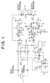
- Fig. 1 is a circuit diagram showing the embodiment of the lubricating oil pump drive circuit for a two-cycle engine according to the invention.
- designated at 1 is an AC generator, more definitely a magneto generator, which is driven from the engine and has an auxiliary coil connected to the input terminals of the embodiment of the circuit.
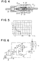
- Fig. 2 shows the construction of the AC generator 1.
- the rotor 11 of the generator is a four-pole permanent magnet having two N poles and two S poles and is driven from the engine.
- the rotor 11 has an inner yoke, on which three coils 12 are wound such as to hold an angle difference of 90 degrees.
- the coils 12 are connected in series so that their electromotive forces are added together and connected between an auxiliary coil output terminal and the ground.
- the output from the auxiliary coil output terminal is used as power source for lamps and horn and also used as power source coupled between the input terminals of the embodiment of the circuit.
- Designated at 14 is a coil of a high voltage power source for ignition.
- Designated at 13 is a pick-up coil for ignition timing.
- Fig. 3 shows the auxiliary coil output waveform of the AC generator 1 during idling of the engine.
- the input terminals shown in Fig. 1 are connected to the input side of a bridge rectifier including diodes D1 to D4.
- the output side of the bridge rectifier is connected between the ground and plus terminal of a capacitor C2, which has its minus terminal grounded and is charged by an output current from the bridge rectifier.
- the plus terminal of the capacitor C2 is connected to one of output terminals of the embodiment of the circuit.
- the capacitor C2 is discharged through a solenoid 4 connected between the output terminals and a transistor 5 connected between one of the output terminals and the ground.
- the transistor 5 is on-off controlled by its base current supplied to it through a resistor R11, thus controlling the conduction start timing and conduction period of the solenoid 4.
- a series circuit including a diode D6, a Zener diode ZD2 and a resistor R2 is connected between the output terminals and serves as a snubber circuit to protect the transistor 5 against the inverse electromotive force voltage generated when the solenoid 4 is de-energized.
- the circuit from the diode D7 to the resistor R11 constitutes a circuit for supplying the base current to the transistor 5, and the circuit from the diode D5 to the capacitor C5 constitutes a DC constant voltage power supply for the circuit noted above.
- a three-terminal regulator 2 has its input terminal connected to the plus terminal of a capacitor C3, which is charged by a series circuit of a diode D5 and a resistor R1, and its output terminal connected along with the plus terminal of a capacitor C5 to a DC power supply terminal 3.
- the capacitor C3 and a Zener diode ZD1 in parallel therewith serve to stabilize the input voltage to the three-terminal regulator 2, and the capacitor C5, which is connected between the output terminal of the three-terminal regulator 2 and the ground, serves to stabilize the output voltage of the DC constant voltage power supply.
- a pulse voltage is generated on the juncture point between the resistors R3 and R4, and a base current is supplied as a pulse current to a transistor 6.
- a series circuit of diodes D8 and D9 is connected between the ground and the juncture point between the resistors R3 and R4 and serves to restrict the magnitude of the voltage applied to the base of the transistor 6.
- the transistor 6 has its collector connected through a resistor R5 to a DC power supply terminal 3 and its emitter connected through a resistor R6 to the ground.
- the collector and emitter of the transistor 6 are also connected to the base and emitter, respectively, of a digital transistor 7, thus forming a commonly termed Schmitt trigger circuit.
- the collector of the digital transistor 7 is connected through a resistor R7 to the DC power supply terminal 3 and also connected to a clock terminal CK of a frequency divider 9.
- pulses corresponding in number to those impressed on the base of the transistor 6 are supplied to the clock terminal CK of the frequency divider 9.
- the frequency division factor of the frequency divider 9 may be selected depending on the size of the engine, and in this embodiment it is 256.
- the frequency divider 9 divides the pulse input to its clock teriminal CK and outputs the resultant pulses to the base of a digital transistor 8.
- the digital transistor 8 has its collector connected through a resistor R8 to the DC power supply terminal and its emitter connected to the ground.
- the collector of the digital transistor 8 is also connected through a capacitor C8 to the juncture point of a series circuit of resistors R9 and R10 connected between the DC power supply terminal and the ground.
- the juncture point between the resistors R9 and R10 is connected to a trigger terminal Trig of a one-shot multi-vibrator 10 and also connected through a diode D10 to the DC power supply terminal.
- the voltage on the juncture point between the the resistors R9 and R10 is normally held at a voltage, which is obtained by dividing the DC power supply voltage between the resistors R9 and R10.
- a differential component of the falling of the collector voltage is impressed to generate a "low” pulse.
- the digital transistor 8 is turned off, the differential component of the rising of the collector voltage is impressed on the juncture between the resistors R9 and R10 to generate a " high” pulse.
- a diode D10 provides for peak restriction on the "high” pulse such that the DC power supply voltage is not exceeded.
- the one-shot multi-vibrator 10 includes a timer circuit IC, which has its threshold terminal Th and discharge terminal Dis. These terminals are connected to a CR circuit constituted by a variable resistor VR and a capacitor C9.
- the voltage at an output terminal Vo is held at "high" level for a predetermined period of time from the impression of a "low” pulse on the trigger terminal as determined by the time constasnt of the CR circuit. While the "high" level voltage prevails at the output terminals of the one-shot multi-vibrator, the base current to the transistor 5 is supplied through a resistor R11.
- a capacitor C11 is connected between a control terminal Cont and the ground to remove noise in the internal control voltage in the one-shot multi-vibrator 10.
- Surge absorbers SA1 and SA2 are provided to absorb surges, and capacitors C1, C4, C7 and C10 serve to absorb noise.
- the solenoid 4 is provided in a lubricating oil pump as shown in Fig. 4. As shown in Fig. 4, the solenoid 4 is wound on a sleeve 15. An inner yoke 17 extends into and is secured to the sleeve 15. A plunger 16 is slidably disposed in the sleeve 15 such that it faces the inner yoke 17. A conical coil spring 20 presses the plunger 16 leftwards.
- a magnetic circuit is formed by the plunger 16 and inner yoke 17 together with an end yoke 19 and an outer yoke 18, and an oil path is formed in a nipple 24, the outer yoke 18, the plunger 16 and the inner yoke 17.
- On the oil path are provided a valve 21 biased by a compression coil spring 22 and a valve 23 fitted in the inner yoke 17. Oil is thus allowed to flow only from the nipple 24 to the inner yoke 17.
- the solenoid pump having the above construction supplies lubricating oil in proportion to the number of strokes of the plunger.
- the magnetic circuit of the lubricating oil pump generates a magnetic flux to attract the plunger 16 to the side of the inner yoke 17 so as to close the magnetic gap between the inner yoke 17 and plunger 16, thus causing discharge of lubricating oil.
- the plunger 16 is returned to the position shown in Fig. 4 by the restoring force of the conical coil spring 20.
- the output energy of the AC generator 1 is stored in the capacitor while the engine is rotated a predetermined number of rotations, and the stored energy drives the lubricating oil pump.
- the lubricating oil pump can be driven reliably even at a low rotational rate of the engine during idling thereof.
- a magnet generator which is usually used for an engine provides a high output peak voltage even when the rotational rate of the engine is low, as shown in Fig. 3.
- the capacitor is charged up to the vicinity of the output peak voltage. Thus, sufficient energy is stored. Further, with the high voltage built up by the charging a high rush energy is provided to the solenoid, which is an inductive load, thus obtaining a high attraction force to attract the plunger.
- the period of time to energize the solenoid is set to an optimum value by the variable resistor VR independently of the rotational rate of the engine.
- the peaks of the output voltage of the AC generator 1 are counted, and the lubricating oil pump is driven for every predetermined number of rotations of the engine.
- Fig. 6 shows a modification of the above embodiment.
- a circuit from a NOR gate 25 to a resistor R11 is substituted for the circuit from the digital transistor 8 to the resistor R11 shown in Fig. 1.
- the remainder of the construction is the same as that of the circuit shown in Fig. 1.
- the output of frequency divider 9 is input to the input terminal of the NOR gate 25.
- the output of the NOR gate 25 is input to the input terminals of NOR gates 26 and 27.
- the output terminal of the NOR gate 26 is connected through a circuit including a resistor Rt, a diode D11 and a capacitor Ct to the ground.
- the common juncture point to the resistor Rt, diode D11 and capacitor Ct is connected through a resistor R12 to the other input terminal of the NOR gate 27.
- the base current to transistor 5 is supplied from the output terminal of the NOR gate 27 through the resistor R11.
- This circuit can attain the function of the one-shot multi-vibrator shown in Fig. 1 as well.
- the conduction time of the transistor 5 is determined by the time constant of the CR circuit formed by the resistor Rt and the capacitor Ct.
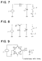
- Fig. 7 shows a different embodiment of the invention.
- the output of AC generator 1 is half-wave rectified by a diode D12 before charging capacitor C2.
- the charge stored in the capacitor C2 is discharged through solenoid 4 and transistor 5.
- a base current supply circuit (not shown) for the transistor 5 supplies a base current periodically like the previous embodiment. This embodiment is inferior in the energy storage efficiency but has the effects of the invention.
- Fig. 8 shows a further embodiment of the invention.
- the output of AC generator 1 is half-wave rectified by a transistor 28 before charging capacitor C2.
- the charge stored in the capacitor C2 is discharged through solenoid 4 and transistor 5.
- the base current to the transistor 28 is supplied through a resistor R13 only for the half-wave rectification period.
- the emitter-collector voltage across the transistor is lower than the forward voltage drop across the diode, and thus the terminal voltage of charging across the capacitor can be increased compared to the case of the diode.
- Fig. 9 shows a still further embodiment of the invention.
- the output of AC generator 1 is rectified by a full-wave rectifier including diodes D1 to D4 and then coupled through a diode D13 to capacitor C2 for the charging thereof. While the charge stored in the capacitor C2 drives the solenoid, the circuit to this end is the same as that in the previous embodiments and hence is not shown. Positive pulse voltage appears from the anode of the dode D13, and these pulses are utilized as the engine rotational rate signal.
- the circuit for controlling the solenoid according to the engine rotational rate signal is the same as the circuit including the diode D7 and the other elements shown in Fig. 1 and hence is not shown.
Landscapes
- Engineering & Computer Science (AREA)
- Mechanical Engineering (AREA)
- General Engineering & Computer Science (AREA)
- Electromagnetic Pumps, Or The Like (AREA)
- Lubrication Of Internal Combustion Engines (AREA)
- Ignition Installations For Internal Combustion Engines (AREA)
Claims (18)
- Circuit de commande de pompe à lubrifiant d'un moteur comprenant un générateur à courant alternatif (1) commandé par le moteur; et un condensateur (C2) pour stocker de l'énergie obtenue par le redressement d'une sortie du générateur à courant alternatif (1), caractérisé en ce que le moteur est un moteur à deux temps, ladite sortie du générateur à courant alternatif est fournie par une bobine auxiliaire (12), et en ce que le condensateur est déchargé périodiquement par un élément de commutation (5) par l'intermédiaire d'un électro-aimant (4) d'une pompe à électro-aimant.
- Circuit selon la revendication 1, comprenant en outre un circuit de contrôle de rotation de moteur connecté à la sortie du générateur à courant alternatif (1) pour déterminer la vitesse de rotation du moteur, le circuit de contrôle étant aussi connecté à l'élément de commutation (5) pour contrôler le temps de mise en route de l'élément de commutation conformément à la vitesse de rotation observée.
- Circuit selon la revendication 2, comprenant en outre un circuit de déclenchement Schmitt auquel est alimentée la sortie du générateur à courant alternatif avant redressement, la sortie du circuit de déclenchement Schmitt étant appliquée à un diviseur de fréquence (9); et un générateur de signal de contrôle d'élément de commutation connecté à la sortie du diviseur de fréquence (9) pour générer un signal de contrôle en réponse à la sortie du diviseur de fréquence (9) pour application à l'élément de commutation (5).
- Circuit selon la revendication 3, dans lequel le générateur de signal de contrôle d'élément de commutation comprend un multivibrateur monostable (10).
- Circuit selon la revendication 3, dans lequel le générateur de signal de contrôle d'élément de commutation comprend un circuit logique remplissant la fonction d'un multivibrateur monostable.
- Circuit selon la revendication 5, dans lequel le circuit logique comprend une première porte NI (25) vers une entrée de laquelle est alimentée la sortie du diviseur de fréquence (9); des deuxième et troisième portes NI (26, 27) auxquelles la sortie de la première porte NI (25) est alimentée en parallèle; et un circuit comprenant une résistance (Rt) et un redresseur (D11) connectés en parallèle et à la sortie de la deuxième porte NI (26), la sortie du circuit étant alimentée vers l'autre entrée de la troisième porte NI (27), où la sortie de la troisième porte NI (27) constitue le signal de contrôle d'élément de commutation.
- Circuit selon l'une quelconque des revendications précédentes, dans lequel le redressement de la sortie du générateur à courant alternatif (1) est fourni par un redresseur à pont.
- Circuit selon l'une quelconque des revendications 1 à 6, dans lequel la sortie du générateur à courant alternatif subit un redressement demi-onde par une diode (D12).
- Circuit selon l'une quelconque des revendications 1 à 6, dans lequel la sortie du générateur à courant alternatif subit un redressement demi-onde par un transistor (28).
- Circuit selon l'une quelconque des revendications 1 à 6, dans lequel la sortie du générateur à courant alternatif (1) subit un redressement pleine-onde par un redresseur pleine-onde, la sortie du redresseur étant alimentée vers une autre diode (D13) avant de charger le condensateur (C2).
- Circuit selon l'une quelconque des revendications précédentes, dans lequel un circuit amortisseur (D6, ZD2, R2) est connecté en parallèle à travers l'électro-aimant (4).
- Circuit selon l'une quelconque des revendications précédentes, dans lequel l'élément de commutation (5) comprend un transistor.
- Circuit selon l'une quelconque des revendications précédentes, dans lequel la sortie du générateur à courant alternatif est fournie par une pluralité de bobines auxiliaires (12) connectées en série.
- Circuit selon la revendication 13, dans lequel chacune des bobines auxiliaires (12) est disposée sensiblement à 90 degrés par rapport aux bobines auxiliaires adjacentes.
- Circuit selon l'une quelconque des revendications précédentes, dans lequel la/les bobine(s) auxiliaire(s) (12) agit/agissent aussi comme une source d'énergie pour d'autres composants, tels que des lampes et/ou un klaxon.
- Moteur à deux temps comprenant une pompe à lubrifiant incluant un électro-aimant (4), et un circuit de contrôle selon l'une quelconque des revendications précédentes pour contrôler le fonctionnement de la pompe.
- Moteur selon la revendication 16, dans lequel le générateur à courant alternatif comprend en outre une bobine d'allumage (14) qui agit comme une source d'énergie à haute tension pour l'allumage du moteur.
- Moteur selon la revendication 16 ou 17, dans lequel le générateur à courant alternatif comprend en outre une bobine exploratrice (13) pour temporiser l'allumage du moteur.
Priority Applications (3)
| Application Number | Priority Date | Filing Date | Title |
|---|---|---|---|
| DE1992612485 DE69212485T2 (de) | 1992-10-27 | 1992-10-27 | Schmierölpumpensteuerschaltung für eine Zweitakt-Brennkraftmaschine |
| EP19920309829 EP0594903B1 (fr) | 1992-10-27 | 1992-10-27 | Circuit de commande de pompe à lubrifiant pour un moteur à combustion interne à deux temps |
| ES92309829T ES2092059T3 (es) | 1992-10-27 | 1992-10-27 | Circuito de accionamiento de bomba de aceite lubricante para motor de dos tiempos. |
Applications Claiming Priority (1)
| Application Number | Priority Date | Filing Date | Title |
|---|---|---|---|
| EP19920309829 EP0594903B1 (fr) | 1992-10-27 | 1992-10-27 | Circuit de commande de pompe à lubrifiant pour un moteur à combustion interne à deux temps |
Publications (2)
| Publication Number | Publication Date |
|---|---|
| EP0594903A1 EP0594903A1 (fr) | 1994-05-04 |
| EP0594903B1 true EP0594903B1 (fr) | 1996-07-24 |
Family
ID=8211529
Family Applications (1)
| Application Number | Title | Priority Date | Filing Date |
|---|---|---|---|
| EP19920309829 Expired - Lifetime EP0594903B1 (fr) | 1992-10-27 | 1992-10-27 | Circuit de commande de pompe à lubrifiant pour un moteur à combustion interne à deux temps |
Country Status (3)
| Country | Link |
|---|---|
| EP (1) | EP0594903B1 (fr) |
| DE (1) | DE69212485T2 (fr) |
| ES (1) | ES2092059T3 (fr) |
Families Citing this family (1)
| Publication number | Priority date | Publication date | Assignee | Title |
|---|---|---|---|---|
| DE10016344A1 (de) * | 2000-03-31 | 2001-10-04 | Wacker Werke Kg | Verbrennungsmotor mit eine Ölpumpe mit Energie versorgender Zündeinrichtung |
-
1992
- 1992-10-27 ES ES92309829T patent/ES2092059T3/es not_active Expired - Lifetime
- 1992-10-27 EP EP19920309829 patent/EP0594903B1/fr not_active Expired - Lifetime
- 1992-10-27 DE DE1992612485 patent/DE69212485T2/de not_active Expired - Fee Related
Also Published As
| Publication number | Publication date |
|---|---|
| DE69212485T2 (de) | 1997-02-27 |
| EP0594903A1 (fr) | 1994-05-04 |
| DE69212485D1 (de) | 1996-08-29 |
| ES2092059T3 (es) | 1996-11-16 |
Similar Documents
| Publication | Publication Date | Title |
|---|---|---|
| US3911886A (en) | Ignition system for an internal combustion engine | |
| US4537174A (en) | Output supply control apparatus for internal combustion engine magneto generator | |
| KR0147080B1 (ko) | 자동차의 차체진동 저감장치 | |
| US3515109A (en) | Solid state ignition with automatic timing advance | |
| JP2005315254A (ja) | コンデンサ放電型点火システム | |
| US4938200A (en) | Ignition device | |
| CA1194536A (fr) | Magneto a un seul enroulement et commutateur de transfert entre le dispositif d'allumage a decharge de condensateur et une charge | |
| US3864621A (en) | Transistorized control circuit for magneto motor ignition systems | |
| EP0594903B1 (fr) | Circuit de commande de pompe à lubrifiant pour un moteur à combustion interne à deux temps | |
| US5404859A (en) | Ignition system for internal combustion engine | |
| EP1764502A2 (fr) | Dispositif d'allumage | |
| US3280810A (en) | Semiconductor ignition system | |
| US5513619A (en) | Discharge ignition apparatus for internal combustion engine | |
| JPH0745865B2 (ja) | 内燃機関用点火装置 | |
| JP2717464B2 (ja) | 2サイクルエンジン用分離潤滑油ポンプ駆動回路 | |
| EP1691053B1 (fr) | Circuit de commande pour système d'allumage à décharge de condensateur | |
| CA1310356C (fr) | Systeme d'allumage | |
| US3853107A (en) | Capacitive discharge ignition system | |
| JP2657181B2 (ja) | 2サイクルエンジン用分離潤滑油ポンプ駆動回路 | |
| US4428333A (en) | Electronic ignition device for combustion engines | |
| US4612493A (en) | Control device for charging generator | |
| US5806503A (en) | Discharge ignition apparatus for internal combustion engine having stepped spark advance | |
| JP2930778B2 (ja) | オルタネータを用いたエンジン制振装置 | |
| CA2195793C (fr) | Systeme d'allumage pour moteurs a combustion interne | |
| JP2750397B2 (ja) | 磁石発電機の電圧制御回路 |
Legal Events
| Date | Code | Title | Description |
|---|---|---|---|
| PUAI | Public reference made under article 153(3) epc to a published international application that has entered the european phase |
Free format text: ORIGINAL CODE: 0009012 |
|
| AK | Designated contracting states |
Kind code of ref document: A1 Designated state(s): DE ES FR GB IT |
|
| 17P | Request for examination filed |
Effective date: 19940929 |
|
| 17Q | First examination report despatched |
Effective date: 19950426 |
|
| GRAH | Despatch of communication of intention to grant a patent |
Free format text: ORIGINAL CODE: EPIDOS IGRA |
|
| GRAA | (expected) grant |
Free format text: ORIGINAL CODE: 0009210 |
|
| AK | Designated contracting states |
Kind code of ref document: B1 Designated state(s): DE ES FR GB IT |
|
| GRAH | Despatch of communication of intention to grant a patent |
Free format text: ORIGINAL CODE: EPIDOS IGRA |
|
| REF | Corresponds to: |
Ref document number: 69212485 Country of ref document: DE Date of ref document: 19960829 |
|
| ITF | It: translation for a ep patent filed | ||
| ET | Fr: translation filed | ||
| REG | Reference to a national code |
Ref country code: ES Ref legal event code: FG2A Ref document number: 2092059 Country of ref document: ES Kind code of ref document: T3 |
|
| PLBE | No opposition filed within time limit |
Free format text: ORIGINAL CODE: 0009261 |
|
| 26N | No opposition filed | ||
| REG | Reference to a national code |
Ref country code: GB Ref legal event code: IF02 |
|
| PGFP | Annual fee paid to national office [announced via postgrant information from national office to epo] |
Ref country code: FR Payment date: 20021008 Year of fee payment: 11 |
|
| PGFP | Annual fee paid to national office [announced via postgrant information from national office to epo] |
Ref country code: GB Payment date: 20021023 Year of fee payment: 11 |
|
| PGFP | Annual fee paid to national office [announced via postgrant information from national office to epo] |
Ref country code: ES Payment date: 20021031 Year of fee payment: 11 Ref country code: DE Payment date: 20021031 Year of fee payment: 11 |
|
| PG25 | Lapsed in a contracting state [announced via postgrant information from national office to epo] |
Ref country code: GB Free format text: LAPSE BECAUSE OF NON-PAYMENT OF DUE FEES Effective date: 20031027 |
|
| PG25 | Lapsed in a contracting state [announced via postgrant information from national office to epo] |
Ref country code: ES Free format text: LAPSE BECAUSE OF NON-PAYMENT OF DUE FEES Effective date: 20031028 |
|
| PG25 | Lapsed in a contracting state [announced via postgrant information from national office to epo] |
Ref country code: DE Free format text: LAPSE BECAUSE OF NON-PAYMENT OF DUE FEES Effective date: 20040501 |
|
| GBPC | Gb: european patent ceased through non-payment of renewal fee |
Effective date: 20031027 |
|
| PG25 | Lapsed in a contracting state [announced via postgrant information from national office to epo] |
Ref country code: FR Free format text: LAPSE BECAUSE OF NON-PAYMENT OF DUE FEES Effective date: 20040630 |
|
| REG | Reference to a national code |
Ref country code: FR Ref legal event code: ST |
|
| REG | Reference to a national code |
Ref country code: ES Ref legal event code: FD2A Effective date: 20031028 |
|
| PG25 | Lapsed in a contracting state [announced via postgrant information from national office to epo] |
Ref country code: IT Free format text: LAPSE BECAUSE OF NON-PAYMENT OF DUE FEES;WARNING: LAPSES OF ITALIAN PATENTS WITH EFFECTIVE DATE BEFORE 2007 MAY HAVE OCCURRED AT ANY TIME BEFORE 2007. THE CORRECT EFFECTIVE DATE MAY BE DIFFERENT FROM THE ONE RECORDED. Effective date: 20051027 |