EP0594921A1 - Vorrichtung zum Aufbringen von entfernbaren Auskleidungen in Behältern - Google Patents
Vorrichtung zum Aufbringen von entfernbaren Auskleidungen in Behältern Download PDFInfo
- Publication number
- EP0594921A1 EP0594921A1 EP92830595A EP92830595A EP0594921A1 EP 0594921 A1 EP0594921 A1 EP 0594921A1 EP 92830595 A EP92830595 A EP 92830595A EP 92830595 A EP92830595 A EP 92830595A EP 0594921 A1 EP0594921 A1 EP 0594921A1
- Authority
- EP
- European Patent Office
- Prior art keywords
- vessel
- liner
- end portions
- cylindric
- expansible
- Prior art date
- Legal status (The legal status is an assumption and is not a legal conclusion. Google has not performed a legal analysis and makes no representation as to the accuracy of the status listed.)
- Granted
Links
Images
Classifications
-
- B—PERFORMING OPERATIONS; TRANSPORTING
- B29—WORKING OF PLASTICS; WORKING OF SUBSTANCES IN A PLASTIC STATE IN GENERAL
- B29C—SHAPING OR JOINING OF PLASTICS; SHAPING OF MATERIAL IN A PLASTIC STATE, NOT OTHERWISE PROVIDED FOR; AFTER-TREATMENT OF THE SHAPED PRODUCTS, e.g. REPAIRING
- B29C57/00—Shaping of tube ends, e.g. flanging, belling or closing; Apparatus therefor, e.g. collapsible mandrels
- B29C57/005—Shaping of tube ends, e.g. flanging, belling or closing; Apparatus therefor, e.g. collapsible mandrels the end of an internal lining
-
- B—PERFORMING OPERATIONS; TRANSPORTING
- B29—WORKING OF PLASTICS; WORKING OF SUBSTANCES IN A PLASTIC STATE IN GENERAL
- B29C—SHAPING OR JOINING OF PLASTICS; SHAPING OF MATERIAL IN A PLASTIC STATE, NOT OTHERWISE PROVIDED FOR; AFTER-TREATMENT OF THE SHAPED PRODUCTS, e.g. REPAIRING
- B29C63/00—Lining or sheathing, i.e. applying preformed layers or sheathings of plastics; Apparatus therefor
- B29C63/26—Lining or sheathing of internal surfaces
- B29C63/28—Lining or sheathing of internal surfaces applied by "rubber" bag or diaphragm
Definitions
- the present invention relates to an apparatus for automatically applying a removable inner liner to vessels or containers in general.
- the inner surface of the vessels is usually coated by a coating layer or liner, conventionally made of plastic material bags, which are usually made of polyethylene or the like.
- the bag material can be easily torn or broken, expecially when, for removing the contained product, there are used collecting metal scraping elements and the like.
- the main object of the present invention is to solve the above mentioned problems, by providing an apparatus for automatically applying an inner coating or liner layer, of the easily removable type, in vessels in general, which is specifically designed for automatically performing all of the operations for applying said inner liner, while providing a perfect adhesion of the inner liner to the inner surface of the vessel.
- a main object of the present invention is to provide such an apparatus which also allows the possibility of properly coating also the edge or rim of the vessel, so as to prevent the formation of regions at which leakages can occur between the inner wall of the vessel and the inner liner layer.
- Another object of the present invention is to provide such an apparatus which also affords the possibility of easily removing the liner, as required, by means of simple operations and in a very reduced time, and which apparatus, moreover, is very reliable and safe in operation.
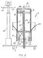
- an apparatus for automatically applying a removable inner liner layer, in vessels in general characterized in that said apparatus comprises, on a supporting framework, a substantially cylindric body, to which a liner element can be applied, and having an expansible and resiliently deformable side surface, and a top wall substantially mating with the inner bottom of a vessel to be lined, said cylindric body being partially housed, at the bottom end portion thereof, in a bell body providing a holding or containment element for the resilient deformation of the bottom portion of the expansible side wall, in order to cause the liner element to adhere to the inner surface of said vessel and to bend the end portions of said inner liner on the edge of the vessel.
- the apparatus for automatically applying an inner coating or liner layer, of a removable type, in vessels or containers in general which has been indicated generally at the reference number 1, comprises a supporting framework 2, on which there is arranged a supporting structure 3, on the top of which there is located a cylindric body, generally indicated at the reference number 4, comprises a rigid material cylindric drum 5, which is closed at the end portions thereof, by a bottom plate 6 and a top plate 7.
- a bottom and top counter-plate Adjoining the plate 6 and 7, there are provided a bottom and top counter-plate, indicated respectively at 8 and 8a, which can be mutually clamped so as to tightly hold the end portions of a tubular membrane 9 made of a resiliently deformable and expansible material.
- the tubular membrane 9 provides, in cooperation with the rigid drum 5, a gap 10 which communicates with a pressurized air source, through a nozzle 11, leading to the rigid drum 5 and connected to the pressure source by means of a pipe 13.
- a bell body 20 which is arranged at the bottom portion of the tubular membrane 9 and is adjustably supported, in order to in turn adjust the position of the bell body, with respect to the free edge or rim of the vessel, as it will become more apparent hereinafter.
- the means for adjusting the height of the bell body 20, comprise a disc 21, including a threaded hole 22, which is supported by the support 3 and engages with a rotary threaded shaft or spindle 24, in turn axially supported in said drum 10 and adapted to be connected with a removable crank 25.
- the disc 21 is connected to an annular body 23, therefrom extend radial pins 27, passing through slots 28 of the support 3, and connected to the bottom portion of the bell body 20, which can be displaced vertically, by causing the threaded spindle or shaft 24 to rotate.
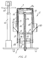
- an inner liner can be applied, said liner comprising a polythene or the like material bag 30, and, after the application of said bag, the vessel 31 can be assembled, so as to assume one of several conventional configurations.
- the top plate has preferably a shape mating with the inner bottom of the vessel or container 31.
- a sealing plate 40 which is supported by a radially extending arm 41, coupled to a column post 42, thereon there are arranged all of the drive means of the apparatus.
- the arm 41 can rotate with respect to the mentioned post, so as to cause the sealing or tightness plate 40 to be moved away, as the vessel must be applied or removed, whereas said plate 40 will be properly located and pressed on the bottom of the vessel during the operating steps of the apparatus.
- the inner liner element 30 is applied, comprising a bag or the like, and, above the latter, there is assembled the vessel 31 as is clearly shown in figure 2.
- pressurized air is supplied inside the bag 10, so as to resiliently deform the tubular membrane 9, which perfectly adheres on the inner wall of the vessel, and so as to cause the inner liner to also perfectly adhere, said inner liner being firmly held since, because of the withdrawing of the air, there is provided a sucker type of effect.
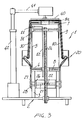
- the tubular membrane which is not herein counterbiassed by the vessel, will be dilated, so as to contact the mentioned bell body, which will operate as a holding or containment element, and, in actual practice, will provide an upwardly turned portion, as clearly shown in figure 3, which will cause the free end portion of the liner to be outwardly turned on the outer rim of the vessel, so that the inner element will perfectly adhere to the walls of the vessel.
- the pressure is removed from the gap 9 and, then, after having also removed the plate 40, the vessel will be withdrawn with the liner perfectly adhering thereon, since the adhesion has been obtained by means of an even pressure effect applied on the overall surface of said liner, owing to the resilient expansion of the membrane.
- the means for positioning the bell body with respect to the cylindric body can be of any suitable types, such as pneumatic pistons or the like.
- the used materials, as well as the contingent shapes and size can be any according to requirements.
Landscapes
- Engineering & Computer Science (AREA)
- Mechanical Engineering (AREA)
- Manufacturing & Machinery (AREA)
- Application Of Or Painting With Fluid Materials (AREA)
- Containers And Packaging Bodies Having A Special Means To Remove Contents (AREA)
- Lining Or Joining Of Plastics Or The Like (AREA)
- Details Of Rigid Or Semi-Rigid Containers (AREA)
Priority Applications (3)
| Application Number | Priority Date | Filing Date | Title |
|---|---|---|---|
| AT92830595T ATE139733T1 (de) | 1992-10-30 | 1992-10-30 | Vorrichtung zum aufbringen von entfernbaren auskleidungen in behältern |
| EP92830595A EP0594921B1 (de) | 1992-10-30 | 1992-10-30 | Vorrichtung zum Aufbringen von entfernbaren Auskleidungen in Behältern |
| DE69211852T DE69211852T2 (de) | 1992-10-30 | 1992-10-30 | Vorrichtung zum Aufbringen von entfernbaren Auskleidungen in Behältern |
Applications Claiming Priority (1)
| Application Number | Priority Date | Filing Date | Title |
|---|---|---|---|
| EP92830595A EP0594921B1 (de) | 1992-10-30 | 1992-10-30 | Vorrichtung zum Aufbringen von entfernbaren Auskleidungen in Behältern |
Publications (2)
| Publication Number | Publication Date |
|---|---|
| EP0594921A1 true EP0594921A1 (de) | 1994-05-04 |
| EP0594921B1 EP0594921B1 (de) | 1996-06-26 |
Family
ID=8212194
Family Applications (1)
| Application Number | Title | Priority Date | Filing Date |
|---|---|---|---|
| EP92830595A Expired - Lifetime EP0594921B1 (de) | 1992-10-30 | 1992-10-30 | Vorrichtung zum Aufbringen von entfernbaren Auskleidungen in Behältern |
Country Status (3)
| Country | Link |
|---|---|
| EP (1) | EP0594921B1 (de) |
| AT (1) | ATE139733T1 (de) |
| DE (1) | DE69211852T2 (de) |
Cited By (3)
| Publication number | Priority date | Publication date | Assignee | Title |
|---|---|---|---|---|
| IT201800020170A1 (it) * | 2018-12-19 | 2020-06-19 | Metalscatola Spa | Macchina per il rivestimento interno di contenitori |
| IT201900003475A1 (it) * | 2019-03-11 | 2020-09-11 | Dromont S P A | Procedimento per applicare elementi di rivestimento all'interno di contenitori |
| EP3848176A3 (de) * | 2019-12-20 | 2021-10-06 | Saier Verpackungstechnik GmbH & Co. KG | Behälter mit in-mould-labeln und/oder mit labeln, verfahren und vorrichtungen zu dessen herstellung sowie deckel und gebinde |
Citations (6)
| Publication number | Priority date | Publication date | Assignee | Title |
|---|---|---|---|---|
| US1993751A (en) * | 1934-03-08 | 1935-03-12 | American Can Co | Method of lining tubular bodies |
| US2065828A (en) * | 1934-01-10 | 1936-12-29 | Kraft Phenix Cheese Corp | Box lining machine |
| FR1436023A (fr) * | 1965-03-10 | 1966-04-22 | Michelin & Cie | Dispositif de retroussage des extrémités d'un manchon élastique autour d'un cylindre rigide |
| DE2737790A1 (de) * | 1976-09-08 | 1978-03-09 | Resistoflex Corp | Verfahren zum herstellen einer erweiterung am ende von einem plastikrohr sowie diesbezuegliches werkzeug |
| US4142453A (en) * | 1977-11-04 | 1979-03-06 | Cvp Systems, Inc. | Flexible container inserting apparatus |
| US4723935A (en) * | 1986-06-26 | 1988-02-09 | Takao Furukawa | Method and apparatus for inserting a bag into an outer packaging box |
-
1992
- 1992-10-30 EP EP92830595A patent/EP0594921B1/de not_active Expired - Lifetime
- 1992-10-30 AT AT92830595T patent/ATE139733T1/de not_active IP Right Cessation
- 1992-10-30 DE DE69211852T patent/DE69211852T2/de not_active Expired - Fee Related
Patent Citations (6)
| Publication number | Priority date | Publication date | Assignee | Title |
|---|---|---|---|---|
| US2065828A (en) * | 1934-01-10 | 1936-12-29 | Kraft Phenix Cheese Corp | Box lining machine |
| US1993751A (en) * | 1934-03-08 | 1935-03-12 | American Can Co | Method of lining tubular bodies |
| FR1436023A (fr) * | 1965-03-10 | 1966-04-22 | Michelin & Cie | Dispositif de retroussage des extrémités d'un manchon élastique autour d'un cylindre rigide |
| DE2737790A1 (de) * | 1976-09-08 | 1978-03-09 | Resistoflex Corp | Verfahren zum herstellen einer erweiterung am ende von einem plastikrohr sowie diesbezuegliches werkzeug |
| US4142453A (en) * | 1977-11-04 | 1979-03-06 | Cvp Systems, Inc. | Flexible container inserting apparatus |
| US4723935A (en) * | 1986-06-26 | 1988-02-09 | Takao Furukawa | Method and apparatus for inserting a bag into an outer packaging box |
Cited By (7)
| Publication number | Priority date | Publication date | Assignee | Title |
|---|---|---|---|---|
| IT201800020170A1 (it) * | 2018-12-19 | 2020-06-19 | Metalscatola Spa | Macchina per il rivestimento interno di contenitori |
| EP3670148A1 (de) * | 2018-12-19 | 2020-06-24 | Metalscatola S.p.a | Maschine zur internen beschichtung von behältern |
| IT201900003475A1 (it) * | 2019-03-11 | 2020-09-11 | Dromont S P A | Procedimento per applicare elementi di rivestimento all'interno di contenitori |
| EP3708334A1 (de) * | 2019-03-11 | 2020-09-16 | Dromont S.p.A. | Verfahren zum anbringen von auskleidungen im inneren von behältern |
| CN111674656A (zh) * | 2019-03-11 | 2020-09-18 | 德罗蒙特股份公司 | 用于在容器内部施加内衬的方法 |
| US11731286B2 (en) | 2019-03-11 | 2023-08-22 | Dromont S.P.A. | Method for applying liners inside containers |
| EP3848176A3 (de) * | 2019-12-20 | 2021-10-06 | Saier Verpackungstechnik GmbH & Co. KG | Behälter mit in-mould-labeln und/oder mit labeln, verfahren und vorrichtungen zu dessen herstellung sowie deckel und gebinde |
Also Published As
| Publication number | Publication date |
|---|---|
| DE69211852D1 (de) | 1996-08-01 |
| EP0594921B1 (de) | 1996-06-26 |
| DE69211852T2 (de) | 1997-02-13 |
| ATE139733T1 (de) | 1996-07-15 |
Similar Documents
| Publication | Publication Date | Title |
|---|---|---|
| US3918605A (en) | Combination container with disposable closure and linear assembly | |
| US5680959A (en) | Bulk container with removable liner, discharge fitment for the liner, and adapter for connection to discharge port of the container | |
| RU2459669C2 (ru) | Устройство для распределения при помощи насоса текучих веществ, содержащихся в герметичных условиях в деформируемом мешке, помещенном в жесткий контейнер | |
| US3377766A (en) | Lined containers | |
| US5676512A (en) | Thin walled cover for aerosol container and method of making same | |
| US9950301B2 (en) | Mixing machine and its liner | |
| US4140543A (en) | Method and apparatus for emptying and cleaning viscous product from a drum | |
| GB1455797A (en) | Method for the liquid-tight welding of a sealable cast nozzle into a thin-walled container for liquid | |
| US5794670A (en) | Tank liner and method of installation | |
| US5046634A (en) | Drum liner assembly | |
| US6789780B2 (en) | Unit and method for discharging loose material from a dispensing device | |
| EP0456403B1 (de) | Behälter für Schüttgut mit biegsamer Verkleidung mit einem Mitnehmer | |
| JPH0699000B2 (ja) | 液体化学薬品取扱い装置 | |
| EP0594921B1 (de) | Vorrichtung zum Aufbringen von entfernbaren Auskleidungen in Behältern | |
| US20160375416A1 (en) | Mixing Machine and Discharging Station | |
| US2139961A (en) | Sediment remover | |
| JPH05310281A (ja) | 気体、液体、ペースト状材料またはそれに類似の生成物を収容する圧力容器 | |
| US6068152A (en) | Shipping container for highly viscous fluids and/or pastes | |
| US5282550A (en) | Bulk material container with a flexible liner | |
| US5503701A (en) | Method for providing recyclable steel drum for hot flow products | |
| JP3944836B2 (ja) | 容器のライニング方法 | |
| JPH03502133A (ja) | 容器リーク検知装置 | |
| US4674262A (en) | Device for releasably holding a container on a feed connection piece | |
| US12371213B2 (en) | Lid supply for a sealer and a sealer | |
| US3880324A (en) | Paste-liquid dispenser with removable puncture rod |
Legal Events
| Date | Code | Title | Description |
|---|---|---|---|
| PUAI | Public reference made under article 153(3) epc to a published international application that has entered the european phase |
Free format text: ORIGINAL CODE: 0009012 |
|
| AK | Designated contracting states |
Kind code of ref document: A1 Designated state(s): AT DE ES FR GB IT NL SE |
|
| 17P | Request for examination filed |
Effective date: 19940920 |
|
| 17Q | First examination report despatched |
Effective date: 19951023 |
|
| GRAH | Despatch of communication of intention to grant a patent |
Free format text: ORIGINAL CODE: EPIDOS IGRA |
|
| GRAH | Despatch of communication of intention to grant a patent |
Free format text: ORIGINAL CODE: EPIDOS IGRA |
|
| GRAA | (expected) grant |
Free format text: ORIGINAL CODE: 0009210 |
|
| AK | Designated contracting states |
Kind code of ref document: B1 Designated state(s): AT DE ES FR GB IT NL SE |
|
| PG25 | Lapsed in a contracting state [announced via postgrant information from national office to epo] |
Ref country code: NL Free format text: LAPSE BECAUSE OF FAILURE TO SUBMIT A TRANSLATION OF THE DESCRIPTION OR TO PAY THE FEE WITHIN THE PRESCRIBED TIME-LIMIT Effective date: 19960626 Ref country code: ES Free format text: THE PATENT HAS BEEN ANNULLED BY A DECISION OF A NATIONAL AUTHORITY Effective date: 19960626 Ref country code: AT Effective date: 19960626 |
|
| REF | Corresponds to: |
Ref document number: 139733 Country of ref document: AT Date of ref document: 19960715 Kind code of ref document: T |
|
| REF | Corresponds to: |
Ref document number: 69211852 Country of ref document: DE Date of ref document: 19960801 |
|
| ITF | It: translation for a ep patent filed | ||
| PG25 | Lapsed in a contracting state [announced via postgrant information from national office to epo] |
Ref country code: SE Effective date: 19960926 |
|
| ET | Fr: translation filed | ||
| NLV1 | Nl: lapsed or annulled due to failure to fulfill the requirements of art. 29p and 29m of the patents act | ||
| PLBE | No opposition filed within time limit |
Free format text: ORIGINAL CODE: 0009261 |
|
| 26N | No opposition filed | ||
| REG | Reference to a national code |
Ref country code: GB Ref legal event code: IF02 |
|
| PGFP | Annual fee paid to national office [announced via postgrant information from national office to epo] |
Ref country code: GB Payment date: 20061025 Year of fee payment: 15 |
|
| PGFP | Annual fee paid to national office [announced via postgrant information from national office to epo] |
Ref country code: DE Payment date: 20061030 Year of fee payment: 15 |
|
| PGFP | Annual fee paid to national office [announced via postgrant information from national office to epo] |
Ref country code: IT Payment date: 20061031 Year of fee payment: 15 |
|
| GBPC | Gb: european patent ceased through non-payment of renewal fee |
Effective date: 20071030 |
|
| PG25 | Lapsed in a contracting state [announced via postgrant information from national office to epo] |
Ref country code: DE Free format text: LAPSE BECAUSE OF NON-PAYMENT OF DUE FEES Effective date: 20080501 |
|
| REG | Reference to a national code |
Ref country code: FR Ref legal event code: ST Effective date: 20080630 |
|
| PGFP | Annual fee paid to national office [announced via postgrant information from national office to epo] |
Ref country code: FR Payment date: 20061011 Year of fee payment: 15 |
|
| PG25 | Lapsed in a contracting state [announced via postgrant information from national office to epo] |
Ref country code: GB Free format text: LAPSE BECAUSE OF NON-PAYMENT OF DUE FEES Effective date: 20071030 |
|
| PG25 | Lapsed in a contracting state [announced via postgrant information from national office to epo] |
Ref country code: FR Free format text: LAPSE BECAUSE OF NON-PAYMENT OF DUE FEES Effective date: 20071031 |
|
| PG25 | Lapsed in a contracting state [announced via postgrant information from national office to epo] |
Ref country code: IT Free format text: LAPSE BECAUSE OF NON-PAYMENT OF DUE FEES Effective date: 20071030 |