EP0594933A1 - Procédé pour fabriquer des chauffes-eau instantanés électriques pour liquides - Google Patents
Procédé pour fabriquer des chauffes-eau instantanés électriques pour liquides Download PDFInfo
- Publication number
- EP0594933A1 EP0594933A1 EP93105465A EP93105465A EP0594933A1 EP 0594933 A1 EP0594933 A1 EP 0594933A1 EP 93105465 A EP93105465 A EP 93105465A EP 93105465 A EP93105465 A EP 93105465A EP 0594933 A1 EP0594933 A1 EP 0594933A1
- Authority
- EP
- European Patent Office
- Prior art keywords
- heating element
- coil
- tubular
- tube
- heater
- Prior art date
- Legal status (The legal status is an assumption and is not a legal conclusion. Google has not performed a legal analysis and makes no representation as to the accuracy of the status listed.)
- Granted
Links
Images
Classifications
-
- F—MECHANICAL ENGINEERING; LIGHTING; HEATING; WEAPONS; BLASTING
- F24—HEATING; RANGES; VENTILATING
- F24H—FLUID HEATERS, e.g. WATER OR AIR HEATERS, HAVING HEAT-GENERATING MEANS, e.g. HEAT PUMPS, IN GENERAL
- F24H1/00—Water heaters, e.g. boilers, continuous-flow heaters or water-storage heaters
- F24H1/10—Continuous-flow heaters, i.e. heaters in which heat is generated only while the water is flowing, e.g. with direct contact of the water with the heating medium
- F24H1/12—Continuous-flow heaters, i.e. heaters in which heat is generated only while the water is flowing, e.g. with direct contact of the water with the heating medium in which the water is kept separate from the heating medium
- F24H1/14—Continuous-flow heaters, i.e. heaters in which heat is generated only while the water is flowing, e.g. with direct contact of the water with the heating medium in which the water is kept separate from the heating medium by tubes, e.g. bent in serpentine form
- F24H1/142—Continuous-flow heaters, i.e. heaters in which heat is generated only while the water is flowing, e.g. with direct contact of the water with the heating medium in which the water is kept separate from the heating medium by tubes, e.g. bent in serpentine form using electric energy supply
-
- H—ELECTRICITY
- H05—ELECTRIC TECHNIQUES NOT OTHERWISE PROVIDED FOR
- H05B—ELECTRIC HEATING; ELECTRIC LIGHT SOURCES NOT OTHERWISE PROVIDED FOR; CIRCUIT ARRANGEMENTS FOR ELECTRIC LIGHT SOURCES, IN GENERAL
- H05B3/00—Ohmic-resistance heating
- H05B3/78—Heating arrangements specially adapted for immersion heating
- H05B3/82—Fixedly-mounted immersion heaters
Definitions
- the invention relates to a method for producing instantaneous water heaters for liquids according to the preamble of patent claim 1.
- a flow tube is provided for the liquid to be heated, around which a tubular heating element in the form of a coil is placed.
- the latter is provided on its outer jacket with a helical groove, the flanks of which are pressed against the tubular heater inserted into the groove.
- This structure does not require any soldering or welding work, but the production of the flow tube is very complex.
- a continuous-flow heater has become known from DE-OS 3534 754 A1, in which a helical tubular heater is arranged on the continuous tube and is covered with a metal jacket.
- a helical tubular heater is arranged on the continuous tube and is covered with a metal jacket.
- DE-PS 3720 927 also shows a tubular heating element arranged in the form of a spiral on the flow tube. However, due to the narrowly limited contact surfaces between the heating element and the flow tube, the heat transfer is also restricted.
- the covering with a molded part made of insulating material can only improve little here.
- the object of the present invention was therefore to provide a process for the production of instantaneous water heaters of the type described which, with relatively little technical effort and avoiding expensive soldering and welding work, enables the production of an efficient instantaneous water heater in which the heat generated by the radiator has no significant value Losses are transferred to the medium flowing through.
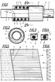
- the instantaneous heater shown in FIG. 1 consists of a continuous tube 1, two half-shells 3 and 4 made of aluminum or the like and holding a helically shaped tubular heating element 2 and a jacket tube 5 made of steel and the two electrical connections 6 for the tubular heating element 2.
- the two half-shells 3 and 4 are produced from an extruded part S, which is provided with a plurality of parallel longitudinal grooves 7 and is available in lengths of up to approximately 6 m.
- pieces corresponding to the length of the continuous-flow heater are cut off, the cut edges S running at an angle to the longitudinal edge of the extruded part S determined by the pitch of the coil of the tubular heating element.
- Two of these pieces separated in this way are now formed into a half-shell 3 or 4, then put together to form an annular body, and the tubular heater 2 previously formed into a spiral is now inserted into the now also helical grooves 7, for example by screwing in.
- the flow tube 1 and the jacket tube 5 are pushed in or over and this structure is subjected to a pressing process.
- the pressure acting here also has the consequence, among other things, that the jacket tube 5 is reduced in diameter and the relatively soft aluminum of the half-shells 3 and 4 is plastically deformed, such that, as shown in FIG. 4, the tube heater is almost in diameter is completely enveloped and an extraordinarily good heat transfer between the radiator and the half-shell is achieved.
- thermal paste can also be applied to the tubular heating element and the flow tube may be applied to close micropores or the like.
- such an order has the advantage that thermal expansions that occur are compensated for.
- the latter can be knurled or fluted on its circumference before installation.
- the instantaneous water heater according to the invention can also be produced without an outer jacket if high operating temperatures are not required.
- the desired helical shape of the grooves 7 is also obtained here.
- the preformed tubular heater can also be installed here by screwing it into the ring body.
Landscapes
- Engineering & Computer Science (AREA)
- Physics & Mathematics (AREA)
- Thermal Sciences (AREA)
- Chemical & Material Sciences (AREA)
- Combustion & Propulsion (AREA)
- Mechanical Engineering (AREA)
- General Engineering & Computer Science (AREA)
- Resistance Heating (AREA)
- Instantaneous Water Boilers, Portable Hot-Water Supply Apparatuses, And Control Of Portable Hot-Water Supply Apparatuses (AREA)
- Heat-Pump Type And Storage Water Heaters (AREA)
Applications Claiming Priority (2)
| Application Number | Priority Date | Filing Date | Title |
|---|---|---|---|
| DE4235989 | 1992-10-24 | ||
| DE4235989A DE4235989A1 (de) | 1992-10-24 | 1992-10-24 | Verfahren zum Herstellen von elektrischen Durchlauferhitzern für Flüssigkeiten |
Publications (2)
| Publication Number | Publication Date |
|---|---|
| EP0594933A1 true EP0594933A1 (fr) | 1994-05-04 |
| EP0594933B1 EP0594933B1 (fr) | 1995-10-11 |
Family
ID=6471291
Family Applications (1)
| Application Number | Title | Priority Date | Filing Date |
|---|---|---|---|
| EP93105465A Expired - Lifetime EP0594933B1 (fr) | 1992-10-24 | 1993-04-02 | Procédé pour fabriquer des chauffes-eau instantanés électriques pour liquides |
Country Status (3)
| Country | Link |
|---|---|
| EP (1) | EP0594933B1 (fr) |
| AT (1) | ATE129114T1 (fr) |
| DE (2) | DE4235989A1 (fr) |
Cited By (2)
| Publication number | Priority date | Publication date | Assignee | Title |
|---|---|---|---|---|
| EP1395085A3 (fr) * | 2002-08-22 | 2005-12-21 | Türk + Hillinger GmbH | Appareil de chauffage électrique pour les corps cylindriques |
| US7703188B2 (en) | 2005-05-19 | 2010-04-27 | Mold-Masters (2007) Limited | Thermal shroud and method of making same |
Families Citing this family (1)
| Publication number | Priority date | Publication date | Assignee | Title |
|---|---|---|---|---|
| DE29910670U1 (de) | 1999-06-18 | 1999-09-23 | Türk & Hillinger GmbH, 78532 Tuttlingen | Durchlauferhitzer mit PTC-Heizelementen |
Citations (2)
| Publication number | Priority date | Publication date | Assignee | Title |
|---|---|---|---|---|
| DE3307962A1 (de) * | 1983-03-07 | 1984-09-20 | Siemens AG, 1000 Berlin und 8000 München | Elektrischer durchlauferhitzer fuer getraenkebereiter |
| DE3534754A1 (de) * | 1985-09-28 | 1987-04-02 | Bauknecht Hausgeraete | Elektrischer durchlauferhitzer fuer haushaltgeraete |
-
1992
- 1992-10-24 DE DE4235989A patent/DE4235989A1/de not_active Withdrawn
-
1993
- 1993-04-02 EP EP93105465A patent/EP0594933B1/fr not_active Expired - Lifetime
- 1993-04-02 AT AT93105465T patent/ATE129114T1/de not_active IP Right Cessation
- 1993-04-02 DE DE59300748T patent/DE59300748D1/de not_active Expired - Fee Related
Patent Citations (2)
| Publication number | Priority date | Publication date | Assignee | Title |
|---|---|---|---|---|
| DE3307962A1 (de) * | 1983-03-07 | 1984-09-20 | Siemens AG, 1000 Berlin und 8000 München | Elektrischer durchlauferhitzer fuer getraenkebereiter |
| DE3534754A1 (de) * | 1985-09-28 | 1987-04-02 | Bauknecht Hausgeraete | Elektrischer durchlauferhitzer fuer haushaltgeraete |
Cited By (2)
| Publication number | Priority date | Publication date | Assignee | Title |
|---|---|---|---|---|
| EP1395085A3 (fr) * | 2002-08-22 | 2005-12-21 | Türk + Hillinger GmbH | Appareil de chauffage électrique pour les corps cylindriques |
| US7703188B2 (en) | 2005-05-19 | 2010-04-27 | Mold-Masters (2007) Limited | Thermal shroud and method of making same |
Also Published As
| Publication number | Publication date |
|---|---|
| ATE129114T1 (de) | 1995-10-15 |
| DE59300748D1 (de) | 1995-11-16 |
| DE4235989A1 (de) | 1994-04-28 |
| EP0594933B1 (fr) | 1995-10-11 |
Similar Documents
| Publication | Publication Date | Title |
|---|---|---|
| EP0000189B1 (fr) | Echangeur de chaleur à collecteurs d'eau en matière plastique et tubes en métal, et son procédé de fabrication | |
| DE3347160A1 (de) | Elektrische heizeinrichtung fuer kunststoffspritzduesen | |
| DE3340359C2 (fr) | ||
| DE102012109740B4 (de) | Elektrische Heizvorrichtung und Verfahren zur Herstellung einer solchen elektrischen Heizvorrichtung | |
| DE2053085B2 (de) | Verfahren und Vorrichtung zur kontinuierlichen Herstellung von Rohren mit wendeiförmigen oder ringförmigen Innenrippen | |
| DE2454920B2 (de) | Elektrischer Durchlauferhitzer | |
| EP0594933B1 (fr) | Procédé pour fabriquer des chauffes-eau instantanés électriques pour liquides | |
| EP2353837B1 (fr) | Dispositif de chauffage électrique doté d'un tuyau oméga | |
| EP3883338B1 (fr) | Chauffage compact pourvu de radiateur à tube de protection | |
| DE2903743C2 (de) | Verfahren zum Herstellen eines elektrischen Durchlauferhitzers | |
| DE19543083A1 (de) | Verfahren und Mittel zum Verschweißen von Wellrohren und/oder Verbundrohren und hiernach erzeugte Schweißverbindung | |
| DE2521754A1 (de) | Heizvorrichtung und verfahren zum herstellen einer heizvorrichtung | |
| DE3925704A1 (de) | Waermeaustauscher | |
| DE3541641A1 (de) | Rohrheizkoerper-heizeinrichtung sowie verfahren zu deren herstellung | |
| DE4226767C1 (en) | Mfg electric through-flow water heater - profiling flow pipe before insertion in extruded metal profile incorporating electric heating elements for improved heat transfer | |
| DE2652656C3 (de) | Elektrischer Durchlauferhitzer für flüssige Medien und Verfahren zu seiner Herstellung | |
| DE2655305C3 (de) | Verfahren zur Herstellung eines elektrischen Rohrheizkörpers | |
| DE4226325C1 (de) | Elektrischer Durchlauferhitzer | |
| DE3303983C1 (de) | Elektrisches Heizelement mit profiliertem Außenmantel | |
| DE19523047C1 (de) | Elektrischer Durchlauferhitzer für flüssige Medien | |
| DE1094383B (de) | Elektrisches Strahlungsheizelement | |
| AT398673B (de) | Heizkörper mit spiralförmig gewickeltem rohrheizkörper sowie verfahren zu seiner herstellung | |
| DE4402020C2 (de) | Verfahren und Anlage zur Herstellung von Wärmetauschern für fluide Wärmeträger sowie druckfester Wärmetausch | |
| DE2660676C2 (de) | Durchlauferhitzer | |
| DE3915272A1 (de) | Heizelement fuer elektrische raumheizkoerper, besonders vom durchflusstyp |
Legal Events
| Date | Code | Title | Description |
|---|---|---|---|
| PUAI | Public reference made under article 153(3) epc to a published international application that has entered the european phase |
Free format text: ORIGINAL CODE: 0009012 |
|
| AK | Designated contracting states |
Kind code of ref document: A1 Designated state(s): AT DE FR GB IT |
|
| ITCL | It: translation for ep claims filed |
Representative=s name: DE DOMINICIS & MAYER S.R.L. |
|
| 17P | Request for examination filed |
Effective date: 19940427 |
|
| GBC | Gb: translation of claims filed (gb section 78(7)/1977) | ||
| EL | Fr: translation of claims filed | ||
| 17Q | First examination report despatched |
Effective date: 19950331 |
|
| GRAA | (expected) grant |
Free format text: ORIGINAL CODE: 0009210 |
|
| AK | Designated contracting states |
Kind code of ref document: B1 Designated state(s): AT DE FR GB IT |
|
| REF | Corresponds to: |
Ref document number: 129114 Country of ref document: AT Date of ref document: 19951015 Kind code of ref document: T |
|
| REF | Corresponds to: |
Ref document number: 59300748 Country of ref document: DE Date of ref document: 19951116 |
|
| ET | Fr: translation filed | ||
| ITF | It: translation for a ep patent filed | ||
| GBT | Gb: translation of ep patent filed (gb section 77(6)(a)/1977) |
Effective date: 19951127 |
|
| PLBE | No opposition filed within time limit |
Free format text: ORIGINAL CODE: 0009261 |
|
| 26N | No opposition filed | ||
| PGFP | Annual fee paid to national office [announced via postgrant information from national office to epo] |
Ref country code: GB Payment date: 19970317 Year of fee payment: 5 |
|
| PG25 | Lapsed in a contracting state [announced via postgrant information from national office to epo] |
Ref country code: GB Free format text: LAPSE BECAUSE OF NON-PAYMENT OF DUE FEES Effective date: 19980402 |
|
| GBPC | Gb: european patent ceased through non-payment of renewal fee |
Effective date: 19980402 |
|
| PGFP | Annual fee paid to national office [announced via postgrant information from national office to epo] |
Ref country code: DE Payment date: 20020211 Year of fee payment: 10 |
|
| PGFP | Annual fee paid to national office [announced via postgrant information from national office to epo] |
Ref country code: AT Payment date: 20020409 Year of fee payment: 10 |
|
| PGFP | Annual fee paid to national office [announced via postgrant information from national office to epo] |
Ref country code: FR Payment date: 20020422 Year of fee payment: 10 |
|
| PG25 | Lapsed in a contracting state [announced via postgrant information from national office to epo] |
Ref country code: AT Free format text: LAPSE BECAUSE OF NON-PAYMENT OF DUE FEES Effective date: 20030402 |
|
| PG25 | Lapsed in a contracting state [announced via postgrant information from national office to epo] |
Ref country code: DE Free format text: LAPSE BECAUSE OF NON-PAYMENT OF DUE FEES Effective date: 20031101 |
|
| PG25 | Lapsed in a contracting state [announced via postgrant information from national office to epo] |
Ref country code: FR Free format text: LAPSE BECAUSE OF NON-PAYMENT OF DUE FEES Effective date: 20031231 |
|
| REG | Reference to a national code |
Ref country code: FR Ref legal event code: ST |
|
| PG25 | Lapsed in a contracting state [announced via postgrant information from national office to epo] |
Ref country code: IT Free format text: LAPSE BECAUSE OF NON-PAYMENT OF DUE FEES;WARNING: LAPSES OF ITALIAN PATENTS WITH EFFECTIVE DATE BEFORE 2007 MAY HAVE OCCURRED AT ANY TIME BEFORE 2007. THE CORRECT EFFECTIVE DATE MAY BE DIFFERENT FROM THE ONE RECORDED. Effective date: 20050402 |