EP0594955B1 - Panneau latéral pour véhicules automobiles - Google Patents
Panneau latéral pour véhicules automobiles Download PDFInfo
- Publication number
- EP0594955B1 EP0594955B1 EP93112245A EP93112245A EP0594955B1 EP 0594955 B1 EP0594955 B1 EP 0594955B1 EP 93112245 A EP93112245 A EP 93112245A EP 93112245 A EP93112245 A EP 93112245A EP 0594955 B1 EP0594955 B1 EP 0594955B1
- Authority
- EP
- European Patent Office
- Prior art keywords
- side panel
- catch
- receiving openings
- panel according
- projections
- Prior art date
- Legal status (The legal status is an assumption and is not a legal conclusion. Google has not performed a legal analysis and makes no representation as to the accuracy of the status listed.)
- Expired - Lifetime
Links
Images



Classifications
-
- B—PERFORMING OPERATIONS; TRANSPORTING
- B60—VEHICLES IN GENERAL
- B60R—VEHICLES, VEHICLE FITTINGS, OR VEHICLE PARTS, NOT OTHERWISE PROVIDED FOR
- B60R13/00—Elements for body-finishing, identifying, or decorating; Arrangements or adaptations for advertising purposes
- B60R13/04—External Ornamental or guard strips; Ornamental inscriptive devices thereon
Definitions
- the invention relates to a side panel for motor vehicles, in particular passenger cars, according to the preamble of patent claim 1.
- a known plastic side cover (DE 37 21 783 A1) for a motor vehicle is connected to the structure at its lower end area by means of fastening screws.
- a clamping device is provided, which is composed of a plug-in part fastened on the body side, a receiving part held in position on the side panel and leaf springs. This receiving part and the leaf springs are fastened to the side panel by means of screws, an additional decorative strip being inserted into the side panel to cover the screw.
- the object of the invention is to design the side sill (sill) and a side cover at least partially covering it so that a simple, quick and inexpensive fastening or assembly of the side cover on the side member is achieved with proper mounting. According to the invention, this object is achieved by the characterizing features of claim 1. Further features which advantageously design the invention contain the subclaims.
- the receiving openings in the side members are used as paint drain openings in the painting (immersion bath) of the vehicle, so that they perform a double function and so there are no further openings in the body.
- Positioning of the side panel in the longitudinal direction is achieved in that a locking lug arranged approximately in the middle of the longitudinal extent of the side panel can be inserted relatively precisely in a corresponding receiving opening of the side longitudinal members, whereas thermal expansion of the side panel can be absorbed in a simple manner by a corresponding width of the other receiving openings .
- the passenger car 1 shown in FIG. 1 has a structure 2 which, in the area shown, comprises a roof 3, a windshield 4, a door 5, a rear side part 6 with a wheel house 7 and a front side part 8 with a wheel house 9. Below the door 5 runs from the front Wheel house 9 to the rear wheel house 7 extending side longitudinal member 10 (sill), which - seen in the vertical direction - is at least partially covered by a side panel 11.
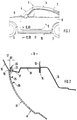
- 2 to 4 is composed of an outer part 12, a web plate 13 and an inner part 14.
- the parts 12, 14 and the web plate 13 are connected to one another at 15 on rectified flanges by welding or the like and form a hollow beam running in the longitudinal direction.
- the outer part 12 comprises a section 16 forming the outer skin, which has a curved shape and is drawn in downwards as viewed in the vertical direction.
- the section 16 is followed by an approximately horizontally oriented or slightly oblique wall section 17 which merges into a step-shaped embossment 18.
- the side cover 11, which is preferably made of plastic, is fastened in such a way that locally formed locking lugs 20 are provided on an upper end region 19 of the side cover 11, which are inserted into receiving openings 21 of the side longitudinal members 10.
- the approximately rectangular receiving openings 21 are provided on the wall section 17 of the outer part 12 of the side longitudinal members 10.
- the side cover 11 In an insertion position A, the side cover 11 can be inserted into the receiving openings 21, the latching lug 20 being oriented approximately perpendicular to the wall section 17 (FIG. 2).
- the transverse extent D of the receiving opening 21 is dimensioned such that it is somewhat larger than the thickness D1 of the detents 20.
- the latching lugs 20 are provided on an overhead end region 19 of the side cover 11, whereby they protrude above the side cover 11.
- the detents 20 are integrally formed with the side panel 11 and are molded onto the side panel 11. But there is also the possibility that the locking lugs 20 in a middle or one underlying region 22 of the vertical extent of the side panel 11 are arranged.
- the locking lugs 20 are provided at intervals of approximately 100-200 mm on the side panel 11 and extend evenly distributed over the entire longitudinal extent of the side panel 11 at.
- the side cladding 11 has a cross-sectional widening 24 in the region of the web 23.
- internal stiffening ribs 25, 26 are provided on the side panel 11, which extend continuously over the longitudinal extent of the side panel 11.
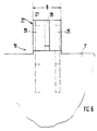
- each locking lug 20 is connected to the upright web 23 of the side cover 11 arranged at the end and extends at an angle to this web 23.
- each locking lug 20 comprises a continuous flange 27 which extends over the width B of the locking lug 20 and on which on both sides at least one a projecting rib 28, 29 is provided. In the operating position C, the flange 27 is aligned approximately parallel to the wall section 16 of the side member 10.
- a central rib 28 is provided on the side facing the wall section 16, whereas two ribs 29 on the outside are formed on the opposite side of the flange 27. These two ribs 29 extend to the inside of the side cover 11, wherein they run approximately parallel to the flange 27 in a first region 30 and approximately parallel to the web 23 in a second region 31.
- the ribs 28, 29 are provided with an upper insertion bevel 32, 32 'for easier insertion of the locking lugs 20.
- the side panel 11 extends continuously between the two wheelhouses 7, 9 of the passenger car.
- a receiving opening 21 for a latch 20 arranged approximately in the middle of the longitudinal extent of the side panel 11 is only slightly wider than the width B of the latch 20 (0.5-1.5 mm per side). whereas the other receiving openings 21 for the corresponding locking lugs 20 are each 2-4 mm larger for tolerance compensation on both sides of the locking lug 20.
- the lower edge region 22 of the side cover 11 is connected to the structure 2 by means of screws, rivets, clips or the like.
- FIG. 4 for the fastening of the lower edge region 22 of the side cover 11 on the inner part 14 of the side member 10, downward-facing welding bolts 33 with an external thread are attached, onto which nuts or push buttons 34 can be placed.
- An end region of the side cover 11 is clamped between the underside of the part 14 and an upper region of the nut or the push button 34.
- it has slot openings 35 which are open towards the inside in the lower fastening region.
- the side cover 11 Viewed in cross section, the side cover 11 has a curved shape that continues the contour of the longitudinal beam 10.
- the side cladding has a step-shaped, upwardly directed shoulder 36 which is pulled further up in the area of the fastening points.
- the side cladding 11 is connected to the respective wheelhouse 7, 9 via a clip connection (not shown in more detail).
- a clip attached to the stiffening ribs 25, 26 is floating.
Landscapes
- Engineering & Computer Science (AREA)
- Mechanical Engineering (AREA)
- Body Structure For Vehicles (AREA)
Claims (9)
- Panneau latéral pour véhicules automobiles, en particulier voitures particulières, recouvrant au moins une zone partielle des supports longitudinaux latéraux (bas de marche) de la carrosserie, une zone d'extrémité - lorsqu'on observe dans la direction de la hauteur - du panneau latéral étant maintenue en position au moyen d'organes de fixation séparés, caractérisé en ce que sont formés d'un seul tenant localement sur le panneau latéral (11) des ergots d'encliquetage (20) qui coopèrent avec des ouvertures de logement (21) des supports longitudinaux (10) latéraux, de manière que les ergots d'encliquetage (20) puissent être introduits dans les ouvertures de logement (21), dans une position d'introduction (A) du panneau latéral (11) et que, par pivotement du panneau latéral (11) en position de fonctionnement (C), les ergots d'encliquetage (20) saisissent par l'arrière les ouvertures de logement (21) et prennent appui sur le support longitudinal (10) latéral.
- Panneau latéral selon la revendication 1, caractérisé en ce que les ouvertures de logement (21) ménagées sur les supports longitudinaux (10) latéraux servent d'ouverture d'évacuation des fuites lors de l'immersion dans un bain de la voiture particulière.
- Panneau latéral selon la revendication 1, caractérisé en ce que les ergots d'encliquetage (20) sont prévus sur une zone d'extrémité (19) supérieure du panneau latéral (11) et pénètrent vers le haut dans le panneau latéral (11).
- Panneau latéral selon les revendications 1 et 3, caractérisé en ce que les ergots d'encliquetage (20) sont réalisés d'un seul tenant par surinjection sur le panneau latéral (11) fabriqué en matière plastique.
- Panneau latéral selon les revendications 1, 3 et 4, caractérisé en ce que les ergots d'encliquetage (20) se raccordent à une nervure (23) montante à une extrémité du panneau latéral (11) et sont orientés en faisant un angle par rapport à cette nervure (23).
- Panneau latéral selon l'une ou plusieurs des revendications précédentes, caractérisé en ce que chaque ergot d'encliquetage (20) comprend un rebord (27) ininterrompu s'étendant sur la largeur (B) de l'ergot d'encliquetage (20) et sur lequel de part et d'autre est prévue au moins une nervure (28, 29) en saillie.
- Panneau latéral selon l'une ou plusieurs des revendications précédentes, caractérisé en ce que le panneau latéral (11) appuie par la nervure montante (23) d'extrémité sur la face inférieure d'une section de paroi (17), s'étendant à peu près horizontalement ou obliquement, du support longitudinal (10) et que les ouvertures de logement (21) sont prévues sur cette section de paroi (17).
- Panneau latéral selon l'une ou plusieurs des revendications précédentes, caractérisé en ce que les ouvertures de logement (21) sont de forme rectangulaire.
- Panneau latéral selon l'une ou plusieurs des revendications précédentes, caractérisé en ce qu'une ouverture de logement (21) destinée à un ergot d'encliquetage (20) disposé à peu près au centre de la longueur du panneau latéral (11) n'est que légèrement plus large que la largeur (B) de l'ergot d'encliquetage (20), alors que, par contre, les autres ouvertures latérales (21) présentent de part et d'autre de l'ergot d'encliquetage (20) respectif une plage de compensation de tolérance plus grande.
Applications Claiming Priority (2)
| Application Number | Priority Date | Filing Date | Title |
|---|---|---|---|
| DE4232192A DE4232192C2 (de) | 1992-09-25 | 1992-09-25 | Seitenverkleidung für Kraftfahrzeuge |
| DE4232192 | 1992-09-25 |
Publications (3)
| Publication Number | Publication Date |
|---|---|
| EP0594955A2 EP0594955A2 (fr) | 1994-05-04 |
| EP0594955A3 EP0594955A3 (en) | 1994-08-17 |
| EP0594955B1 true EP0594955B1 (fr) | 1996-04-10 |
Family
ID=6468860
Family Applications (1)
| Application Number | Title | Priority Date | Filing Date |
|---|---|---|---|
| EP93112245A Expired - Lifetime EP0594955B1 (fr) | 1992-09-25 | 1993-07-30 | Panneau latéral pour véhicules automobiles |
Country Status (2)
| Country | Link |
|---|---|
| EP (1) | EP0594955B1 (fr) |
| DE (2) | DE4232192C2 (fr) |
Families Citing this family (6)
| Publication number | Priority date | Publication date | Assignee | Title |
|---|---|---|---|---|
| DE19620404C1 (de) * | 1996-05-21 | 1997-08-14 | Porsche Ag | Verkleidungsteil aus nachgiebigem Werkstoff für einen Endbereich eines Fahrzeuges, insbesondere Personenkraftwagen |
| JP3772265B2 (ja) * | 2000-05-17 | 2006-05-10 | 株式会社シマノ | 釣り用塗装部品 |
| US7066529B2 (en) | 2003-12-01 | 2006-06-27 | Hyundai Translead | Cargo carrying container with peripheral wall structure incorporating a corrugated sheet |
| DE102006001028A1 (de) * | 2006-01-02 | 2007-07-12 | Decoma (Germany) Gmbh | Verkleidungsteil |
| DE102010049795A1 (de) * | 2010-10-27 | 2012-05-03 | Audi Ag | Vorrichtung zur Befestigung eines Verkleidungsteils an einer Innenverkleidung eines Kraftfahrzeugs |
| DE102018212718A1 (de) | 2018-07-31 | 2020-02-06 | Bayerische Motoren Werke Aktiengesellschaft | Befestigungssystem zur Befestigung eines Kennzeichenträgers an einem Fahrzeugbauteil eines einspuringen Kraftfahrzeugs |
Family Cites Families (5)
| Publication number | Priority date | Publication date | Assignee | Title |
|---|---|---|---|---|
| US3842565A (en) * | 1973-05-21 | 1974-10-22 | Robin Prod Co | Resilient buffer assembly |
| JPS59171714A (ja) * | 1983-03-04 | 1984-09-28 | Honda Motor Co Ltd | 自動車用ドア |
| DE3606812A1 (de) * | 1986-03-03 | 1987-09-17 | Daimler Benz Ag | Verkleidung fuer einen einstiegsschweller eines kraftfahrzeugs |
| SE458918B (sv) * | 1986-07-02 | 1989-05-22 | Saab Scania Ab | Anordning foer monterbar anfaestning av ett taeckelement |
| JPH0263944A (ja) * | 1988-08-30 | 1990-03-05 | Suzuki Motor Co Ltd | クォータトリムの取付構造 |
-
1992
- 1992-09-25 DE DE4232192A patent/DE4232192C2/de not_active Expired - Fee Related
-
1993
- 1993-07-30 DE DE59302180T patent/DE59302180D1/de not_active Expired - Fee Related
- 1993-07-30 EP EP93112245A patent/EP0594955B1/fr not_active Expired - Lifetime
Also Published As
| Publication number | Publication date |
|---|---|
| DE4232192C2 (de) | 1995-08-31 |
| DE4232192A1 (de) | 1994-03-31 |
| DE59302180D1 (de) | 1996-05-15 |
| EP0594955A2 (fr) | 1994-05-04 |
| EP0594955A3 (en) | 1994-08-17 |
Similar Documents
| Publication | Publication Date | Title |
|---|---|---|
| EP1088746B1 (fr) | Module de toit véhiculaire avec ensemble de toit coulissant intégré | |
| EP0380013B1 (fr) | Système de fixation d'un ciel de toit pour la construction d'un toit coulissant ou toit coulissant basculant | |
| DE4133002C2 (fr) | ||
| DE19735068C2 (de) | Energieabsorbierende Verkleidung für eine Aufbausäule eines Kraftfahrzeuges | |
| EP0175121A1 (fr) | Tableau d'instruments pour véhicules | |
| EP0253967B1 (fr) | Pare-chocs pour véhicule | |
| DE10013427C2 (de) | Kraftwagenbug | |
| EP1920998A1 (fr) | Carrosserie de véhicule automobile et procédé de montage de celle-ci | |
| DE10359768A1 (de) | Fahrzeugkarosserie | |
| DE3545973A1 (de) | Fuer den einbau geeignetes hebe- und/oder schiebedach | |
| EP0185892B1 (fr) | Fixation amovible d'une moulure décorative | |
| EP0594955B1 (fr) | Panneau latéral pour véhicules automobiles | |
| DE3243802A1 (de) | Ablageschale mit deckel, insbesondere zur aufnahme von verbandsmaterial | |
| EP1348585B1 (fr) | Panneau déplaçable pour toit de véhicule et module pour toit coulissant | |
| DE19524506C2 (de) | Vorderkotflügelverstärkungsstruktur | |
| DE102015000463A1 (de) | Befestigungsanordnung zur Montage einer Zierblende und/oder einer Scheibenführung an einer Fahrzeugtür | |
| DE102019114304A1 (de) | Fahrzeug mit einer Dichtungsanordnung | |
| EP0872408B1 (fr) | Agencement pour le tableau de bord d'un véhicule automobile | |
| DE4426155C2 (de) | Kraftfahrzeug, insbesondere Personenkraftwagen | |
| DE60009465T2 (de) | Vorrichtung zur befestigung einer an einer stossstange integrierten kotflügelverbreiterung | |
| EP0531720B1 (fr) | Système de fixation pour des éléments de montage visibles pour véhicules, en particulier véhicules automobiles | |
| EP1182086B1 (fr) | Ensemble collecteur d'eau pour un véhicule | |
| DE3606812A1 (de) | Verkleidung fuer einen einstiegsschweller eines kraftfahrzeugs | |
| DE4230082A1 (de) | Rahmenkonstruktion eines sonnendachs | |
| DE19654446C2 (de) | Kraftfahrzeug mit einer Karosserietragstruktur und Montagelehre |
Legal Events
| Date | Code | Title | Description |
|---|---|---|---|
| PUAI | Public reference made under article 153(3) epc to a published international application that has entered the european phase |
Free format text: ORIGINAL CODE: 0009012 |
|
| AK | Designated contracting states |
Kind code of ref document: A2 Designated state(s): DE FR GB IT |
|
| PUAL | Search report despatched |
Free format text: ORIGINAL CODE: 0009013 |
|
| AK | Designated contracting states |
Kind code of ref document: A3 Designated state(s): DE FR GB IT |
|
| 17P | Request for examination filed |
Effective date: 19950118 |
|
| 17Q | First examination report despatched |
Effective date: 19950925 |
|
| ITF | It: translation for a ep patent filed | ||
| GRAA | (expected) grant |
Free format text: ORIGINAL CODE: 0009210 |
|
| AK | Designated contracting states |
Kind code of ref document: B1 Designated state(s): DE FR GB IT |
|
| REF | Corresponds to: |
Ref document number: 59302180 Country of ref document: DE Date of ref document: 19960515 |
|
| ET | Fr: translation filed | ||
| GBT | Gb: translation of ep patent filed (gb section 77(6)(a)/1977) |
Effective date: 19960510 |
|
| PLBE | No opposition filed within time limit |
Free format text: ORIGINAL CODE: 0009261 |
|
| 26N | No opposition filed | ||
| PGFP | Annual fee paid to national office [announced via postgrant information from national office to epo] |
Ref country code: FR Payment date: 19980629 Year of fee payment: 6 |
|
| PGFP | Annual fee paid to national office [announced via postgrant information from national office to epo] |
Ref country code: DE Payment date: 19990720 Year of fee payment: 7 |
|
| PGFP | Annual fee paid to national office [announced via postgrant information from national office to epo] |
Ref country code: GB Payment date: 19990728 Year of fee payment: 7 |
|
| PG25 | Lapsed in a contracting state [announced via postgrant information from national office to epo] |
Ref country code: FR Free format text: THE PATENT HAS BEEN ANNULLED BY A DECISION OF A NATIONAL AUTHORITY Effective date: 19990731 |
|
| REG | Reference to a national code |
Ref country code: FR Ref legal event code: ST |
|
| PG25 | Lapsed in a contracting state [announced via postgrant information from national office to epo] |
Ref country code: GB Free format text: LAPSE BECAUSE OF NON-PAYMENT OF DUE FEES Effective date: 20000730 |
|
| GBPC | Gb: european patent ceased through non-payment of renewal fee |
Effective date: 20000730 |
|
| PG25 | Lapsed in a contracting state [announced via postgrant information from national office to epo] |
Ref country code: DE Free format text: LAPSE BECAUSE OF NON-PAYMENT OF DUE FEES Effective date: 20010501 |
|
| PG25 | Lapsed in a contracting state [announced via postgrant information from national office to epo] |
Ref country code: IT Free format text: LAPSE BECAUSE OF NON-PAYMENT OF DUE FEES Effective date: 20050730 |