EP0594976A2 - Medium voltage switchgear - Google Patents
Medium voltage switchgear Download PDFInfo
- Publication number
- EP0594976A2 EP0594976A2 EP93113832A EP93113832A EP0594976A2 EP 0594976 A2 EP0594976 A2 EP 0594976A2 EP 93113832 A EP93113832 A EP 93113832A EP 93113832 A EP93113832 A EP 93113832A EP 0594976 A2 EP0594976 A2 EP 0594976A2
- Authority
- EP
- European Patent Office
- Prior art keywords
- switch
- earthing
- panel according
- connection
- outgoing
- Prior art date
- Legal status (The legal status is an assumption and is not a legal conclusion. Google has not performed a legal analysis and makes no representation as to the accuracy of the status listed.)
- Granted
Links
Images


Classifications
-
- H—ELECTRICITY
- H02—GENERATION; CONVERSION OR DISTRIBUTION OF ELECTRIC POWER
- H02B—BOARDS, SUBSTATIONS OR SWITCHING ARRANGEMENTS FOR THE SUPPLY OR DISTRIBUTION OF ELECTRIC POWER
- H02B13/00—Arrangement of switchgear in which switches are enclosed in, or structurally associated with, a casing, e.g. cubicle
- H02B13/02—Arrangement of switchgear in which switches are enclosed in, or structurally associated with, a casing, e.g. cubicle with metal casing
- H02B13/035—Gas-insulated switchgear
- H02B13/075—Earthing arrangements
Definitions
- the invention relates to a metal-encapsulated medium-voltage switchgear panel with a load switch and at least one earthing switch according to the preamble of claim 1.
- This field width so the object of the invention, should be reduced even further without having to do without an obligatory and powerful earthing switch; it is also an object of the invention to further improve the design by simplified creation of active panel parts.
- this object is achieved by an outgoing connection arranged between the cable and switch disconnector, which is designed as a molded part, in particular as a cast part, and in the interior of which fixed contacts for contacting the movable switching arms of the earthing switch are arranged.
- the outgoing connection is thus a universal active part, which not only the static connections, e.g. B. by screw connections between the load switch and cable or an interposed HV fuse, but also houses the high-voltage mating contacts for the earthing switch. Wall parts leading into the interior of the outlet connection in the form of slots or other depressions can themselves form the fixed contact points, i. H. special built-in contacts are not necessary.
- the outgoing connections can be implemented at low voltage, since they do not have to carry any external field-distorting contact structures. Therefore, an optimally favorable field width can be achieved with them.
- the respective outlet connection can also have a support surface for an insulation support; it is useful to equip these insulators with capacitive divider elements for a voltage display.
- HV HRC fuses are inserted between the cable and the load switch, there is an additional outlet connection on the cable end side on the circuit breaker side. This extends the functionality of an outgoing connection; it now also has an additional holder for the HV fuses.
- the cable termination side outlet connection such a recording, which is equipped with appropriate spring contacts; furthermore a connection lug for contacting the cable end closure, one or more slots for receiving a knife contact of the earthing switch and finally a support surface for an insulation support, which runs primarily at an angle to the drop line of the switch panel.
- the circuit breaker-side outlet connection can in any case be cylindrical with regard to its outer contour when using fuses; it contains a corresponding fuse holder, parallel slots for a pair of contact blades for the earthing switch and screw-on points for non-rotating contact with the switch disconnector.
- the earthing switch is accommodated in such a way that the dielectric strength of the switching field is optimal.
- the invention provides the following measures for this:
- the drive shaft of the earthing switch is largely shielded from live parts by an insulating apron on the side of the switch-disconnector housing, and the switching arms of the earthing switch lie in the open position along the outer wall of the switch panel and are as close as possible to it.
- the switching arms (earthing knife) of the earthing are rigidly coupled to a right-angled connecting arm, which sits firmly on the earth drive shaft. This creates an angle arm, which in particular allows the use of shortened switching arms.
- a cable earth If a cable earth is present, it can be coupled to the single earth drive shaft near the circuit breaker, via a coupling that is connected to the drive shaft by means of a link.
- Another handlebar is connected to a drive shaft of the cable earth, which is mounted hard on the outer wall of the switchgear and carries an earthing knife, and drives it.
- the earthing knife of the cable earth electrode is also expediently in its switch-off position along the outside of the switch panel and in its immediate vicinity.
- a control panel 10 has a control panel housing 11, which is formed from metallic encapsulation walls 12, 13, 14 and 15. The front wall is not shown.
- the encapsulation walls 12 and 13 are side walls and the encapsulation walls 14 and 15 are the lower and upper end walls.
- a load-break switch 17 is installed in the central plane 16, the housing 18 of which is sealed hermetically and gas-tight and filled with SF6 gas for arc quenching or insulation.
- the load break switch 17 is a three-pole switch, the poles of which are identified by the reference numerals 171, 172 and 173.
- the individual poles 171, 172 and 173 have on the upper side of the switch disconnector 17 upper connecting pieces 19, 20 and 21, which correspond to the lower connecting pieces shown in dashed lines in FIG.
- each outlet end element 33 has a support plane 34 running at approximately 45 °, against which one end of a support insulator 35 rests; the other end of the post insulator 35 is attached to a bracket 36; the post insulator for each outlet termination element is oriented at an angle of approximately 45 ° to the central plane 16.
- the console 36 is fastened to the side wall 13 by means of screw connections 37.
- each pole there is associated with each pole an earthing switch 38, the switch knife 39, which is L-shaped, can be contacted with a suitable contact point on the outlet terminating element 33.
- the switch knife 39 rotates about an axis 40, the shorter leg 41 being dimensioned such that it can reach under the insulating apron 31.
- the earthing switch of FIG. 3 is designed differently than that of FIG. 1, which will be explained in more detail below; nevertheless, the insulating apron 31 or 32 is the same as in FIG. 1.
- the load break switch 17 is attached to a support plate 42 in the housing.
- a connection extension 43 is formed on the outlet termination element, to which a cable outlet, not shown, can be connected.
- the connectors 19, 20th and 21 serve to make contact with one or more busbars, not shown.
- FIG. 2 shows the front wall 44 and the rear wall 45.
- a drive shaft 46 (see FIG. 2) of the earthing switch 39 is provided, which runs between the front wall 44 and the rear wall 45 and from the insulating apron opposite the lower connecting pieces 22 and is shielded from the outlet termination elements 33.
- a switch-off spring 47 is also indicated in FIG. 2.
- Support insulators 351, 3521 and 353, which are assigned to the lower connecting pieces 22, can also be seen in FIG.
- a second connection element 48 connects to the lower connection piece 22 of each pole, shown in broken lines, which, in the same way as the outgoing connection element 33, has means for contacting an earthing switch.
- the second outgoing terminating element 48 is cylindrical and has a recess 49 in its lower region, into which a connection head 50 of a high-voltage high-performance fuse 51 (shortly known as HV fuse) is inserted.
- a contact spring 52 (see further below) is used in the recess 49 for contacting the head 50 with the second outlet termination element 48.
- the lower end of the HH fuse 51 with the head 53 is inserted into a recess 54 of a third outlet terminating element 56, in which recess 54 a contact spring 55 is inserted, which corresponds to the contact spring 52.
- the third outlet end element 56 is approximately cylindrical; this is followed by an inclined plane 58, the angle of which to the central plane 16 is the angle corresponds to the connection or support plane 34, with which a support insulator 59 is fixedly connected, which is fastened to a bracket 60 on the side wall 13.
- a flat area 61 adjoins the upper area 57, to which the cable end closure 62 of an outgoing cable 63 is connected with a connecting strap 64.
- Measuring capacitors are cast into the support insulators 35 and 59, and a voltage tester can be connected to their leads (not shown).
- the switch panel according to FIG. 3 has an earthing switch arrangement which differs from that of FIG. 1.
- the grounding circuit arrangement has a first and a second pair of contact blades 71, 72, of which the second pair of contact blades 72 is attached to an actuating shaft 73.
- the distance between the two pairs of contact blades 71, 72 corresponds to the length of the HV fuse.
- a drive bracket 78 is also firmly connected, to which a drive spring 79 connects, which supports the drive movement in the direction of switching on and off, which is not to be shown in more detail here.
- the individual first contact knife pairs 71 are electrically conductively connected by means of a connecting bridge 80 which can be pivoted with the contact knife pairs 71 and which bridge 80 is grounded.
- each pair of contact blades 71 must reach under this apron 31.
- the connecting arm 77 must be dimensioned accordingly.
- FIGS. 4 to 6 show the first outlet end element 33.
- This outlet end element has a cylindrical section 81, on the circumferential line of which a cross-section 82 in the form of a segment of a circle is formed, so that a flat surface 83 is formed on the inside, as a result of which the thickness d is based on a wall thickness T. expanded.
- the cylindrical section 81 has a flat, axially extending extension 84 which has a recess 85 with a concentric bore 86 in the area of the end.
- the cylindrical section is provided with a base 23 in the area of the end face 90, as a result of which a horseshoe-shaped cavity 94 closed by the base 93 is formed in cross section.
- a bore 95 provided in the bottom 93 the element 33 can be fastened to the lower connecting piece by means of a screw connection.
- a tab 64 of a cable 63 can be attached.
- FIG. 7 shows the second connecting piece 48, which has a circular cylindrical cross section, which is closed with a bottom 96.
- slots 97 and 98 corresponding to slots 87 and 88, which form a web 99 between them which corresponds to web 89.
- the end opposite the bottom 96 has a segment-like cutout 99, through which an access opening 100 into the interior of the second outlet end element is formed in the cylinder.
- the inner surface On the wall area opposite the opening 101, the inner surface has an axially extending depression 102, in which the contact spring 52 is fastened by means of a screw connection 103.
- a further slot 104 is provided, into which a trigger element can engage.
- the third outlet termination element 56 is shown in FIGS. 10 to 12. It has a circular section 57 which corresponds to the area of the element 48 with the spring 52; this circular section 57 is adjoined by a flat section or a flat region 61, in which there is an axially extending recess 105 which is open to the outside. At the bottom of the depression in the area of the lower end there is a transversely projecting ledge 106. At the lower end of the depression 105 there is a bore 107, via which both the tab 64 of the cable 63 and a leaf spring 108 are fastened in the depression can; FIG. 11 shows the leaf spring 108.
- the strip 106 bends the leaf spring 108 so that the leaf spring 108 unites takes an oblique angle to the bottom of the recess 105 and thereby serves as a counter-contact for the contact knife 72.
- the inclined support plane 58 is, as can be seen from FIG. 11, formed by an inclined wall 109.
Landscapes
- Engineering & Computer Science (AREA)
- Power Engineering (AREA)
- Arc-Extinguishing Devices That Are Switches (AREA)
- Switch Cases, Indication, And Locking (AREA)
- Rotary Switch, Piano Key Switch, And Lever Switch (AREA)
Abstract
Bei einer Mittelspannungsschaltanlage mit in Anlagentiefe hintereinander liegenden Polen sowie eingebauten Lasttrenn- und Erdungsschaltern wird eine Optimierung der Schaltfeldbreite insbesondere durch am Lasttrennschalter sowie am Kabelendverschluß anbaubare Abgangsanschlüsse (7, 7a, 7b) erreicht, die nicht nur alle Anschlußverbindungen - ggf. auch für HH-Sicherungen - aufweisen, sondern in die auch Fixkontakte für die Schaltarme (10a, 10b) der Erdungsschalter integriert sind. Darüberhinaus lassen sie sich nachbearbeitungsfrei und feldgünstig als Gießteile fertigen.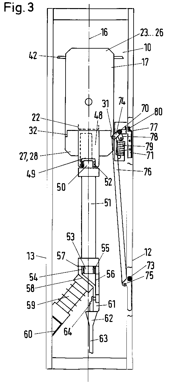
Description
Die Erfindung betrifft ein metallgekapseltes Mittelspannungsschaltfeld mit einem Last- sowie mindestens einem Erdungsschalter gemäß Oberbegriff des Anspruches 1.The invention relates to a metal-encapsulated medium-voltage switchgear panel with a load switch and at least one earthing switch according to the preamble of claim 1.
Bei dem vorgenannten Schaltfeld wird insbesondere durch die in Feldtiefe hintereinander liegenden Phasen eine geringe Feldbreite erzielt.In the aforementioned switching field, a small field width is achieved in particular by the phases lying one behind the other in field depth.
Diese Feldbreite, so die Aufgabe der Erfindung, soll noch weiter verringert werden, ohne auf einen obligatorischen und leistungsfähigen Erdungsschalter verzichten zu müssen; ferner ist es ein Ziel der Erfindung, die Konstruktion durch vereinfachte Erstellung von Schaltfeldaktivteilen noch weiter zu verbessern.This field width, so the object of the invention, should be reduced even further without having to do without an obligatory and powerful earthing switch; it is also an object of the invention to further improve the design by simplified creation of active panel parts.
Diese Aufgabe wird erfindungsgemäß durch die kennzeichnenden Merkmale des Anspruches 1 gelöst.This object is achieved by the characterizing features of claim 1.
Allgemein also wird diese Aufgabe gelöst durch einen zwischen Kabel sowie Lasttrennschalter angeordneten Abgangsanschluß, der als Form-, insbesondere als Gußteil, ausgeführt ist und in dessen Innerem Fixkontakte zur Kontaktierung mit den beweglichen Schaltarmen der Erdungsschalter angeordnet sind.In general, this object is achieved by an outgoing connection arranged between the cable and switch disconnector, which is designed as a molded part, in particular as a cast part, and in the interior of which fixed contacts for contacting the movable switching arms of the earthing switch are arranged.
Der Abgangsanschluß ist somit ein Universalaktivteil, das nicht nur die statischen Anschlüsse, z. B. durch Schraubverbindungen, zwischen dem Lastschalter und Kabel bzw. einer dazwischen gelegten HH-Sicherung herstellt, sondern auch die auf Hochspannungspotential gelegenen Gegenkontakte für den Erdungsschalter berherbergt. Dabei können ins Innere des Abgangsanschlusses führende Wandungsteile in Form von Schlitzen oder anderen Einsenkungen selbst die Fixkontaktstellen bilden, d. h. besondere Kontakteinbauten sind entbehrlich.The outgoing connection is thus a universal active part, which not only the static connections, e.g. B. by screw connections between the load switch and cable or an interposed HV fuse, but also houses the high-voltage mating contacts for the earthing switch. Wall parts leading into the interior of the outlet connection in the form of slots or other depressions can themselves form the fixed contact points, i. H. special built-in contacts are not necessary.
Die Abgangsanschlüsse sind spannungsgünstig verwirklichbar, da sie keine äußeren feldverzerrenden Kontaktaufbauten tragen müssen. Daher ist mit ihnen eine optimal günstige Feldbreite erzielbar. Hinzu kommt, daß durch deren Herstellung, z. B. als Kokillengußteil, Nachbearbeitungen weitestgehend entbehrlich sind. Zusätzlich kann bei Bedarf der jeweilige Abgangsanschluß noch eine Abstützfläche für einen Isolierstützer aufweisen; es ist zweckmäßig diese Isolatoren mit kapazitiven Teilerelementen für eine Spannungsanzeige auszurüsten.The outgoing connections can be implemented at low voltage, since they do not have to carry any external field-distorting contact structures. Therefore, an optimally favorable field width can be achieved with them. In addition, by their manufacture, for. B. as mold casting, post-processing is largely unnecessary. In addition, if necessary, the respective outlet connection can also have a support surface for an insulation support; it is useful to equip these insulators with capacitive divider elements for a voltage display.
Werden HH-Sicherungen zwischen dem Kabel sowie dem Lastschalter eingesetzt, ergibt sich nebem dem lastschalterseitigen ein weiterer kabelendverschlußseitiger Abgangsanschluß. Dadurch erweitert sich die Funktionalität eines Abgangsanschlusses, er besitzt nunmehr zusätzlich noch eine Aufnahme für die HH-Sicherungen. So hat z. B. der kabelendverschlußseitige Abgangsanschluß eine solche Aufnahme, die mit entsprechenden Federkontakten bestückt ist; desweiteren eine Anschlußfahne zum Kontaktieren mit dem Kabelendverschluß, einen oder mehrere Schlitze für die Aufnahme eines Messerkontaktes des Erdungsschalters und schließlich eine, vornehmlich zur Fallinie des Schaltfeldes unter einem Winkel verlaufende Abstützfläche für einen Isolierstützer.If HV HRC fuses are inserted between the cable and the load switch, there is an additional outlet connection on the cable end side on the circuit breaker side. This extends the functionality of an outgoing connection; it now also has an additional holder for the HV fuses. So z. B. the cable termination side outlet connection such a recording, which is equipped with appropriate spring contacts; furthermore a connection lug for contacting the cable end closure, one or more slots for receiving a knife contact of the earthing switch and finally a support surface for an insulation support, which runs primarily at an angle to the drop line of the switch panel.
Der lastschalterseitige Abgangsanschluß kann bei Verwendung von Sicherungen in jedem Falle hinsichtlich seiner Außenkontur zylinderförmig ausgebildet sein; er enthält eine entsprechende Sicherungsaufnahme, parallel laufende Schlitze für ein Kontaktmesserpaar des Erdungsschalters sowie Anschraubstellen zum verdrehsicheren Kontaktieren mit dem Lasttrennschalter.The circuit breaker-side outlet connection can in any case be cylindrical with regard to its outer contour when using fuses; it contains a corresponding fuse holder, parallel slots for a pair of contact blades for the earthing switch and screw-on points for non-rotating contact with the switch disconnector.
Um eine günstige Feldbreite realisieren zu können, ist es ferner wesentlich, daß der Erdungsschalter so untergebracht ist, daß die Spannungsfestigkeit des Schaltfeldes ein Optimum darstellt. Dafür sieht die Erfindung folgende Maßnahmen vor:In order to be able to implement a favorable field width, it is also essential that the earthing switch is accommodated in such a way that the dielectric strength of the switching field is optimal. The invention provides the following measures for this:
Die Antriebswelle des Erdungsschalters ist durch eine seitlich heruntergezogene Isolierschürze des Lasttrennschaltergehäuses gegenüber Spannung führenden Teilen weitestgehend abgeschirmt, und die Schaltarme des Erders liegen in dessen Ausschaltstellung längs zur Schaltfeldaußenwand und sind dieser so weit wie möglich angenähert. Bei der Erdung des lastschalternahen Erders müssen dessen Schaltmesser die Isolierschürze untergreifen. Dazu sind die Schaltarme (Erdungsmesser) des Erders starr mit einem rechtwinklig abgehenden Verbindungsarm gekoppelt, der fest auf der Erderantriebswelle aufsitzt. Dadurch entsteht ein Winkelarm, das insbesondere den Einsatz verkürzter Schaltarme erlaubt.The drive shaft of the earthing switch is largely shielded from live parts by an insulating apron on the side of the switch-disconnector housing, and the switching arms of the earthing switch lie in the open position along the outer wall of the switch panel and are as close as possible to it. When earthing the circuit breaker close to the circuit breaker, its switch blades must reach under the insulating apron. For this purpose, the switching arms (earthing knife) of the earthing are rigidly coupled to a right-angled connecting arm, which sits firmly on the earth drive shaft. This creates an angle arm, which in particular allows the use of shortened switching arms.
Bei Vorhandensein eines Kabelerders, kann dieser mit der lastschalternahen einzigen Erderantriebswelle gekoppelt werden, und zwar über eine Koppel, die mit der Antriebswelle mittels eines Lenkers verbunden ist. Ein weiterer Lenker ist mit einer hart an der Schaltfeldaußenwand gelagerten und ein Erdungsmesser tragenden Betätigungswelle des Kabelerders verbunden und treibt diese an. Auch das Erdungsmesser des Kabelerders liegt zweckmäßigerweise in seiner Ausschaltstellung längs zur Schaltfeldaußenseite und in deren unmittelbarer Nähe.If a cable earth is present, it can be coupled to the single earth drive shaft near the circuit breaker, via a coupling that is connected to the drive shaft by means of a link. Another handlebar is connected to a drive shaft of the cable earth, which is mounted hard on the outer wall of the switchgear and carries an earthing knife, and drives it. The earthing knife of the cable earth electrode is also expediently in its switch-off position along the outside of the switch panel and in its immediate vicinity.
Diese und weitere vorteilhafte Ausgestaltungen und Weiterbildungen der Erfindung sind den Unteransprüchen zu entnehmen.These and further advantageous refinements and developments of the invention can be found in the subclaims.
Anhand der Zeichnung, in der einige Ausführungsbeispiele der Erfindung dargestellt sind, sollen die Erfindung, weitere vorteilhafte Ausgestaltungen und Verbesserungen sowie weitere Vorteile näher erläutert und beschrieben werden.The invention, further advantageous refinements and improvements and further advantages are to be explained and described in more detail with reference to the drawing, in which some exemplary embodiments of the invention are shown.
Es zeigen:
- Figur 1
- eine Vorderansicht eines Schaltfeldes (ohne Frontwand),
- Figur 2
- eine Seitenansicht des Schaltfeldes nach Figur 1 (ohne Seitenaußenwand),
- Figur 3
- eine Vorderansicht eines Schaltfeldes mit HH-Sicherungen,
- Figur 4
- eine Schnittansicht gemäß Schnittlinie IV-IV eines ersten Abgangsabschlußelementes,
- Figur 5
- eine Ansicht gemäß Pfeilrichtung V der Figur 4,
- Figur 6
- eine Schnittansicht gemäß Schnittlinie VI-VI der Figur 4,
Figuren 7, 8 und 9- unterschiedliche Ansichten des zweiten Abgangsabschlußelementes und
Figuren 10 bis 12- unterschiedliche Ansichten des dritten Abgangsabschlußelementes.
- Figure 1
- a front view of a control panel (without front wall),
- Figure 2
- 2 shows a side view of the switch panel according to FIG. 1 (without side outer wall),
- Figure 3
- a front view of a control panel with HV fuses,
- Figure 4
- 2 shows a sectional view according to section line IV-IV of a first outlet termination element,
- Figure 5
- 4 shows a view in the direction of the arrow V in FIG. 4,
- Figure 6
- 3 shows a sectional view according to section line VI-VI of FIG. 4,
- Figures 7, 8 and 9
- different views of the second outlet termination element and
- Figures 10 to 12
- different views of the third outlet termination element.
Es sei nun Bezug genommen auf die Figuren 1 und 2.Reference is now made to FIGS. 1 and 2.
Ein Schaltfeld 10 besitzt ein Schaltfeldgehäuse 11, welches aus metallischen Kapselungswänden 12, 13, 14 und 15 gebildet ist. Die Frontwand ist nicht dargestellt. Die Kapselungswände 12 und 13 sind Seitenwände und die Kapselungswände 14 und 15 die untere und obere Abschlußwandung. In der Mittelebene 16 ist ein Lasttrennschalter 17 eingebaut, dessen Gehäuse 18 hermetisch und gasdicht abgeschlossen und mit SF6-Gas zur Lichtbogenlöschung bzw. Isolierung gefüllt ist. Der Lasttrennschalter 17 ist hierbei ein dreipoliger Schalter, dessen Pole mit den Bezugsziffern 171, 172 und 173 bezeichnet sind. Die einzelnen Pole 171, 172 und 173 besitzen an der oberen Seite des Lasttrennschalters 17 obere Anschlußstücke 19, 20 und 21, denen in Figur 1 gestrichelte dargestellte untere Anschlußstücke entsprechen, die in der Figur 1 mit 22 bezeichnet sind. Zwischen den Polen befinden sich obere Trennwände 23, 24, 25 und 26, die die oberen Anschlußstücke 19, 20 und 21 gegeneinander und gegen das Schaltfeldgehäuse 11 abschirmen; zwischen den unteren Anschlußstücken 22 befinden sich untere Trennwände 27 und 28, denen Trennwände 29 und 30 entsprechen, mit denen die unteren Anschlußstücke 22 gegenüber dem Schaltfeldgehäuse abgeschirmt sind. Zwischen den Trennwänden 30, 28, 27 und 29 befinden sich heruntergezogene Isolierschützen, die in Figur 3 mit den Bezugsziffern 31 und 32 bezeichnet sind.A
An den unteren Anschlußstücken 22 sind Abgangsabschlußelemente 33 für jeden Pol angebracht, die weiter unten näher beschrieben werden. Jedes Abgangsabschlußelement 33 besitzt eine unter ca. 45° verlaufende Stützebene 34, gegen die ein Ende eines Stützisolators 35 anliegt; das andere Ende des Stützisolators 35 ist an einer Konsole 36 befestigt; der Stützisolator für jedes Abgangsabschlußelement ist unter einem Winkel von ca. 45° zur Mittelebene 16 ausgerichtet. Die Konsole 36 ist mittels Schraubenverbindungen 37 an der Seitenwand 13 befestigt.At the lower connecting
An der Seitenwand 12 befindet sich jedem Pol zugeordnet ein Erdungsschalter 38, dessen Schaltermesser 39, das L-förmig ausgebildet ist, mit einer geeigneten Kontaktstelle am Abgangsabschlußelement 33 kontaktiert werden kann. Das Schaltermesser 39 dreht sich dabei um eine Achse 40, wobei der kürzere Schenkel 41 so bemessen ist, daß er die Isolierschürze 31 untergreifen kann. Zwar ist der Erdungsschalter der Figur 3 anders ausgebildet als der der Figur 1, was weiter unten näher erläutert werden soll; gleichwohl ist die Isolierschürze 31 bzw. 32 die gleiche wie in Figur 1.On the
Der Lasttrennschalter 17 ist an einer Tragplatte 42 im Gehäuse befestigt.The
An dem Abgangsabschlußelement ist ein Anschlußfortsatz 43 angeformt, an dem ein nicht näher dargestellter Kabelabgang angeschlossen werden kann. Die Anschlußstücke 19, 20 und 21 dienen zur Kontaktierung mit einer oder mehreren nicht näher dargestellten Sammelschienen. Die Figur 2 zeigt die Frontwand 44 und die Rückwand 45. Zur Betätigung des Erdungsschalters 39 ist eine Antriebswelle 46 (siehe Figur 2) des Erdungsschalters 39 vorgesehen, die zwischen der Frontwand 44 und der Rückwand 45 verläuft und von der Isolierschürze gegenüber den unteren Anschlußstücken 22 und gegenüber den Abgangsabschlußelementen 33 abgeschirmt ist. In der Ausschaltstellung liegen die Schaltermesser 39 des Erdungsschalters an der Seitenwand 12 an; in der Figur 2 ist noch angedeutet eine Ausschaltfeder 47. Man erkennt in der Figur 2 auch die Stützisolatoren 351, 3521 und 353, die den unteren Anschlußstücken 22 zugeordnet sind.A
Es sei nun Bezug genommen auf die Figur 3.Reference is now made to FIG. 3.
An dem strichliert dargestellten unteren Anschlußstück 22 jedes Pols schließt ein zweites Anschlußelement 48 an, welches in gleicher Weise wie das Abgangsabschlußelement 33 Mittel zur Kontaktierung mit einem Erdungsschalter aufweist. Im wesentlichen ist das zweite Abgangsabschlußelement 48 zylinderförmig ausgebildet und besitzt in seinem unteren Bereich eine Ausnehmung 49, in die ein Anschlußkopf 50 einer Hochspannungshochleistungssicherung 51 (kurz HH-Sicherung genannt) eingesetzt ist. Zur Kontaktierung des Kopfes 50 mit dem zweiten Abgangsabschlußelement 48 ist in der Ausnehmung 49 eine Kontaktfeder 52 (siehe weiter unten) eingesetzt. Das untere Ende der HH-Sicherung 51 mit dem Kopf 53 ist in eine Ausnehmung 54 eines dritten Abgangsabschlußelementes 56 eingesetzt, in welcher Ausnehmung 54 eine Kontaktfeder 55 eingesetzt ist, die der Kontaktfeder 52 entspricht. Im oberen Bereich 57 ist das dritte Abgangsabschlußelement 56 etwa zylindrisch; daran schließt sich eine schräg verlaufende Ebene 58 an, deren Winkel zur Mittelebene 16 dem Winkel der Anschluß- oder Abstützebene 34 entspricht, mit der ein Stützisolator 59 fest verbunden ist, der an einer Konsole 60 an der Seitenwand 13 befestigt ist. An dem oberen Bereich 57 schließt ein Flachbereich 61 an, an dem der Kabelendverschluß 62 eines Abgangskabels 63 mit einer Anschlußlasche 64 angeschlossen ist.A
In die Stützisolatoren 35 und 59 sind nicht näher gezeigte Meßkondensatoren eingegossen, an deren herausgeführten Anschlüssen ein Spannungstester anschließbar ist (nicht dargestellt).Measuring capacitors, not shown in more detail, are cast into the
Das Schaltfeld gemäß Figur 3 besitzt eine Erdungsschalteranordnung, die sich von der der Figur 1 unterscheidet. Die Erdungsschaltungsanordnung besitzt ein erstes und ein zweites Kontaktmesserpaar 71, 72, von denen das zweite Kontaktmesserpaar 72 an einer Betätigungswelle 73 angebracht ist. Der Abstand der beiden Kontaktmesserpaare 71, 72 entspricht der Länge der HH-Sicherung. An der Antriebswelle 70 befindet sich eine erste Betätigungskurbel 74 und an der Betätigungswelle 73 eine zweite Kurbel 75, die mittels einer Koppelstange 76 gelenkig verbunden sind. Zwischen dem Kontaktmesserpaar 71 und der Antriebswelle 70 befindet sich ein Verbindungsarm 77, so daß schlußendlich das erste Kontaktmesserpaar 71 bezogen auf die Antriebswelle 70 eine L-Form aufweist. Mit der Antriebswelle 70 ist weiterhin eine Antriebslasche 78 fest verbunden, an der eine Antriebsfeder 79 anschließt, die die Antriebsbewegung in Richtung Ein- bzw. Ausschalten unterstützt, was hier nicht näher dargestellt werden soll. Die einzelnen ersten Kontaktmesserpaare 71 sind mittels einer mit den Kontaktmesserpaaren 71 mitschwenkbaren Verbindungsbrücke 80 elektrisch leitend verbunden, welche Brücke 80 geerdet ist.The switch panel according to FIG. 3 has an earthing switch arrangement which differs from that of FIG. 1. The grounding circuit arrangement has a first and a second pair of
Da, wie bei Figur 1 dargestellt, die Antriebswelle 70 der Erdungsschaltvorrichtung oberhalb der Unterkante der Isolierschürze 31 verläuft, muß jedes Kontaktmesserpaar 71 diese Schürze 31 untergreifen. Demgemäß ist der Verbindungsarm 77 zu bemessen.Since, as shown in FIG. 1, the
Die Figuren 4 bis 6 zeigen das erste Abgangsabschlußelement 33. Dieses Abgangsabschlußelement besitzt einen zylindrischen Abschnitt 81, an dessen einer Mantellinie ein kreissegmentartiger Querschnitt 82 angeformt ist, so daß sich im Inneren eine ebene Fläche 83 bildet, wodurch sich die Dicke d auf eine Wandstärke T erweitert. Im Bereich dieser Mantellinie besitzt der zylindrische Abschnitt 81 eine flach ausgebildete, axial verlaufende Verlängerung 84, die im Bereich des Endes eine Vertiefung 85 mit einer konzentrischen Bohrung 86 aufweist. Im Bereich des kreissegmentförmigen Abschnittes sind zwei parallel zueinander und axial verlaufende Schlitze 87 und 88 vorgesehen, die einen axial verlaufenden Steg 89 zwischen sich bilden, welcher Steg 89 einen Fixkontakt für das Kontaktmesserpaar 39 bildet. Etwa in der Mitte ist der zylindrische Bereich 81 schräg abgeschnitten, wodurch eine unter einem Winkel α gegenüber der Mittellinie M-M verlaufende schräge Stützebene 34 gebildet ist. Die dem unteren Anschlußstück 22 zugewandte, der flachen Verlängerung 84 entgegengesetzt liegende Stirnfläche 90 des Abschlußelementes 33 besitzt an den distalen Mantellinien Vorsprünge 91 und 92, die mit entsprechenden Vertiefungen an dem unteren Anschlußstück 22 korrespondieren, wodurch eine Verdrehsicherheit erreicht wird. Der zylinderförmige Abschnitt ist im Bereich der Stirnfläche 90 mit einem Boden 23 versehen, wodurch sich im Querschnitt etwa eine hufeisenförmige, durch den Boden 93 verschlossene Höhlung 94 bildet. Über eine im Boden 93 vorgesehenen Bohrung 95 kann das Element 33 an dem unteren Anschlußstück mittels einer Schraubenverbindung befestigt werden. An der flachen Verlängerung kann beispielsweise eine Lasche 64 eines Kabels 63 befestigt werden.FIGS. 4 to 6 show the first
Basierend auf dem in den Figuren 4 bis 6 gezeigten Abgangsabschlußelement 33 sind in entsprechender Weise die Abschlußelemente 48 bzw. 56 ähnlich aufgebaut. Die Figur 7 zeigt das zweite Anschlußstück 48, welches einen kreiszylinderförmigen Querschnitt aufweist, der mit einem Boden 96 verschlossen ist. An der Seitenwand befinden sich den Schlitzen 87 und 88 entsprechende Schlitze 97 und 98, die zwischen sich einen Steg 99 bilden, der dem Steg 89 entspricht. Das dem Boden 96 entgegengesetzte Ende besitzt einen einen segmentartigen Ausschnitt 99, durch den im Zylinder eine Zugangsöffnung 100 ins Innere des zweiten Abgangsabschlußelementes gebildet ist. Die Innenfläche besitzt an dem der Öffnung 101 entgegengesetzten Wandbereich eine axial verlaufende Vertiefung 102, in der die Kontaktfeder 52 mittels einer Schraubverbindung 103 befestigt ist. An der den Schlitzen 97 und 98 entgegengesetzt liegenden Seite ist ein weiterer Schlitz 104 vorgesehen, in den ein Auslöseelement eingreifen kann.Based on the
Das dritte Abgangsabschlußelement 56 ist in den Figuren 10 bis 12 dargestellt. Es besitzt einen kreisförmigen Abschnitt 57, der dem Bereich des Elementes 48 mit der Feder 52 entspricht; an diesen kreisförmigen Abschnitt 57 schließt sich ein flacher Abschnitt oder ein Flachbereich 61 an, in dem sich eine axial verlaufende, nach außen offene Vertiefung 105 befindet. Am Boden der Vertiefung im Bereich des unteren Endes befindet sich eine quer verlaufende, vorspringende Leiste 106. Am unteren Ende der Vertiefung 105 befindet sich eine Bohrung 107, über die sowohl die Lasche 64 des Kabels 63 als auch eine Blattfeder 108 in der Vertiefung befestigt werden kann; die Figur 11 zeigt die Blattfeder 108. Die Leiste 106 verbiegt die Blattfeder 108, so daß die Blattfeder 108 einen schrägen Winkel zum Boden der Vertiefung 105 einnimmt und dadurch als Gegenkontakt für das Kontaktmesser 72 dient. Die schräge Stützebene 58 ist dabei, wie aus Figur 11 ersichtlich, durch eine schräg verlaufende Wandung 109 gebildet.The third
Die Abgangsanschlußelemente sind in der obigen Beschreibung lediglich schematisch dargestellt; es sind Abwandlungen denkbar, die im Rahmen der Erfindung liegen.The outgoing connection elements are only shown schematically in the above description; modifications are conceivable that are within the scope of the invention.
Claims (9)
Applications Claiming Priority (4)
| Application Number | Priority Date | Filing Date | Title |
|---|---|---|---|
| DE4229421 | 1992-09-03 | ||
| DE4229421 | 1992-09-03 | ||
| DE4323369 | 1993-07-13 | ||
| DE4323369A DE4323369A1 (en) | 1992-09-03 | 1993-07-13 | Control panel for medium voltage |
Publications (3)
| Publication Number | Publication Date |
|---|---|
| EP0594976A2 true EP0594976A2 (en) | 1994-05-04 |
| EP0594976A3 EP0594976A3 (en) | 1994-07-20 |
| EP0594976B1 EP0594976B1 (en) | 1996-09-18 |
Family
ID=25918199
Family Applications (1)
| Application Number | Title | Priority Date | Filing Date |
|---|---|---|---|
| EP93113832A Expired - Lifetime EP0594976B1 (en) | 1992-09-03 | 1993-08-30 | Medium voltage switchgear |
Country Status (2)
| Country | Link |
|---|---|
| EP (1) | EP0594976B1 (en) |
| DE (2) | DE4323369A1 (en) |
Families Citing this family (1)
| Publication number | Priority date | Publication date | Assignee | Title |
|---|---|---|---|---|
| EP2485353A1 (en) | 2011-02-03 | 2012-08-08 | ABB Technology AG | Electrical connection assembly for an electricity distribution system of a high and/or medium voltage assembly |
Family Cites Families (6)
| Publication number | Priority date | Publication date | Assignee | Title |
|---|---|---|---|---|
| DE666199C (en) * | 1933-08-04 | 1938-10-15 | Reyrolle & Co Ltd A | High voltage switchgear |
| FR2242794B1 (en) * | 1973-08-30 | 1976-11-19 | Merlin Gerin | |
| FR2348592A1 (en) * | 1976-04-12 | 1977-11-10 | Merlin Gerin | Medium voltage switch gear module - has pivoted arms earthing ends of fuse under action of control rod |
| DE3033633A1 (en) * | 1980-09-06 | 1982-04-15 | Calor-Emag Elektrizitäts-Aktiengesellschaft, 4030 Ratingen | Compact multiphase earthing switch - has shafts carrying contact blades for each phase coupled so latter pivot in common plane |
| DE3427800A1 (en) * | 1984-07-25 | 1986-02-06 | Siemens AG, 1000 Berlin und 8000 München | METAL-ENCLOSED, PRESSURE GAS-INSULATED HIGH-VOLTAGE SWITCHGEAR |
| FR2621427B1 (en) * | 1987-10-06 | 1990-11-30 | Merlin Gerin | PREFABRICATED MEDIUM VOLTAGE TABLE WITH ROTARY SWITCH |
-
1993
- 1993-07-13 DE DE4323369A patent/DE4323369A1/en not_active Withdrawn
- 1993-08-30 DE DE59303853T patent/DE59303853D1/en not_active Expired - Fee Related
- 1993-08-30 EP EP93113832A patent/EP0594976B1/en not_active Expired - Lifetime
Also Published As
| Publication number | Publication date |
|---|---|
| DE59303853D1 (en) | 1996-10-24 |
| DE4323369A1 (en) | 1994-03-10 |
| EP0594976B1 (en) | 1996-09-18 |
| EP0594976A3 (en) | 1994-07-20 |
Similar Documents
| Publication | Publication Date | Title |
|---|---|---|
| EP0291762B1 (en) | Metal-clad, gas filled, multiphase high voltage switchgear | |
| EP0688071B2 (en) | Metal-clad gas-insulated switchgear | |
| EP0309386B1 (en) | Multi-pole low-voltage circuit breaker with an insulating case and an arc quencher | |
| EP0069693A2 (en) | Cylindrical container for a three-pole metal-clad gas-insulated high-voltage switchgear | |
| EP0678955B1 (en) | Metal-clad gas-insulated switch installation | |
| EP2254135A1 (en) | Metal-enclosed, multi-phase gas-insulated busbar disconnecting and earthing switch | |
| EP1037239A2 (en) | Multi-pole power switch | |
| EP0152611B1 (en) | Metal-enclosed gas-insulated switch installation | |
| DE3780921T2 (en) | GAS-INSULATED MULTIPOLE ROTARY SWITCH. | |
| EP0205397B1 (en) | Isolating switch for a high-tension gas-insulated metal-clad switchgear | |
| DE2924630C2 (en) | Encapsulated, three-phase rotary disconnector | |
| DE68909370T2 (en) | Three-phase switch in a single housing. | |
| EP0023247A1 (en) | Disconnecting switch | |
| DE3436173A1 (en) | Switching installation | |
| EP1629581B1 (en) | Disconnecting switch assembly | |
| EP0796502B1 (en) | Metal-clad switchgear with a vacuum switching device | |
| EP0594976B1 (en) | Medium voltage switchgear | |
| DE69114370T2 (en) | Gas-insulated switching device. | |
| DE19641391C1 (en) | Hybrid type high-voltage switchgear | |
| DE602004002634T2 (en) | earthing switch | |
| EP0787376B1 (en) | Metal-cladded electrical high-voltage switching installation with a power switch | |
| WO2004109882A2 (en) | Gas-insulated bus bar component comprising outdoor bushings | |
| EP3254350B1 (en) | Casing arrangement | |
| EP1825488B1 (en) | Polyphase switching device comprising at least three similar interrupter units | |
| DE4438787C1 (en) | Metal-enclosed high-voltage switchgear with a three-pole encapsulated busbar |
Legal Events
| Date | Code | Title | Description |
|---|---|---|---|
| PUAI | Public reference made under article 153(3) epc to a published international application that has entered the european phase |
Free format text: ORIGINAL CODE: 0009012 |
|
| AK | Designated contracting states |
Kind code of ref document: A2 Designated state(s): BE DE FR GB IE NL |
|
| PUAL | Search report despatched |
Free format text: ORIGINAL CODE: 0009013 |
|
| RHK1 | Main classification (correction) |
Ipc: H02B 11/28 |
|
| AK | Designated contracting states |
Kind code of ref document: A3 Designated state(s): BE DE FR GB IE NL |
|
| 17P | Request for examination filed |
Effective date: 19940827 |
|
| GRAG | Despatch of communication of intention to grant |
Free format text: ORIGINAL CODE: EPIDOS AGRA |
|
| GRAH | Despatch of communication of intention to grant a patent |
Free format text: ORIGINAL CODE: EPIDOS IGRA |
|
| 17Q | First examination report despatched |
Effective date: 19960221 |
|
| GRAH | Despatch of communication of intention to grant a patent |
Free format text: ORIGINAL CODE: EPIDOS IGRA |
|
| GRAA | (expected) grant |
Free format text: ORIGINAL CODE: 0009210 |
|
| AK | Designated contracting states |
Kind code of ref document: B1 Designated state(s): BE DE FR GB IE NL |
|
| REF | Corresponds to: |
Ref document number: 59303853 Country of ref document: DE Date of ref document: 19961024 |
|
| ET | Fr: translation filed | ||
| REG | Reference to a national code |
Ref country code: IE Ref legal event code: FG4D Free format text: 69911 |
|
| GBT | Gb: translation of ep patent filed (gb section 77(6)(a)/1977) |
Effective date: 19961129 |
|
| PLBE | No opposition filed within time limit |
Free format text: ORIGINAL CODE: 0009261 |
|
| 26N | No opposition filed | ||
| REG | Reference to a national code |
Ref country code: GB Ref legal event code: IF02 |
|
| PGFP | Annual fee paid to national office [announced via postgrant information from national office to epo] |
Ref country code: DE Payment date: 20020703 Year of fee payment: 10 |
|
| PGFP | Annual fee paid to national office [announced via postgrant information from national office to epo] |
Ref country code: IE Payment date: 20020709 Year of fee payment: 10 |
|
| PGFP | Annual fee paid to national office [announced via postgrant information from national office to epo] |
Ref country code: NL Payment date: 20020710 Year of fee payment: 10 |
|
| PGFP | Annual fee paid to national office [announced via postgrant information from national office to epo] |
Ref country code: GB Payment date: 20020711 Year of fee payment: 10 Ref country code: FR Payment date: 20020711 Year of fee payment: 10 |
|
| PGFP | Annual fee paid to national office [announced via postgrant information from national office to epo] |
Ref country code: BE Payment date: 20020830 Year of fee payment: 10 |
|
| PG25 | Lapsed in a contracting state [announced via postgrant information from national office to epo] |
Ref country code: GB Free format text: LAPSE BECAUSE OF NON-PAYMENT OF DUE FEES Effective date: 20030830 |
|
| PG25 | Lapsed in a contracting state [announced via postgrant information from national office to epo] |
Ref country code: BE Free format text: LAPSE BECAUSE OF NON-PAYMENT OF DUE FEES Effective date: 20030831 |
|
| PG25 | Lapsed in a contracting state [announced via postgrant information from national office to epo] |
Ref country code: IE Free format text: LAPSE BECAUSE OF NON-PAYMENT OF DUE FEES Effective date: 20030901 |
|
| BERE | Be: lapsed |
Owner name: *ABB PATENT G.M.B.H. Effective date: 20030831 |
|
| PG25 | Lapsed in a contracting state [announced via postgrant information from national office to epo] |
Ref country code: NL Free format text: LAPSE BECAUSE OF NON-PAYMENT OF DUE FEES Effective date: 20040301 |
|
| PG25 | Lapsed in a contracting state [announced via postgrant information from national office to epo] |
Ref country code: DE Free format text: LAPSE BECAUSE OF NON-PAYMENT OF DUE FEES Effective date: 20040302 |
|
| GBPC | Gb: european patent ceased through non-payment of renewal fee | ||
| PG25 | Lapsed in a contracting state [announced via postgrant information from national office to epo] |
Ref country code: FR Free format text: LAPSE BECAUSE OF NON-PAYMENT OF DUE FEES Effective date: 20040430 |
|
| NLV4 | Nl: lapsed or anulled due to non-payment of the annual fee |
Effective date: 20040301 |
|
| REG | Reference to a national code |
Ref country code: FR Ref legal event code: ST |
|
| REG | Reference to a national code |
Ref country code: IE Ref legal event code: MM4A |