EP0594980A1 - Direction pour véhicule automobile - Google Patents
Direction pour véhicule automobile Download PDFInfo
- Publication number
- EP0594980A1 EP0594980A1 EP93113968A EP93113968A EP0594980A1 EP 0594980 A1 EP0594980 A1 EP 0594980A1 EP 93113968 A EP93113968 A EP 93113968A EP 93113968 A EP93113968 A EP 93113968A EP 0594980 A1 EP0594980 A1 EP 0594980A1
- Authority
- EP
- European Patent Office
- Prior art keywords
- steering
- clutch
- steering wheel
- spindle
- steering spindle
- Prior art date
- Legal status (The legal status is an assumption and is not a legal conclusion. Google has not performed a legal analysis and makes no representation as to the accuracy of the status listed.)
- Granted
Links
Images


Classifications
-
- B—PERFORMING OPERATIONS; TRANSPORTING
- B60—VEHICLES IN GENERAL
- B60R—VEHICLES, VEHICLE FITTINGS, OR VEHICLE PARTS, NOT OTHERWISE PROVIDED FOR
- B60R25/00—Fittings or systems for preventing or indicating unauthorised use or theft of vehicles
- B60R25/01—Fittings or systems for preventing or indicating unauthorised use or theft of vehicles operating on vehicle systems or fittings, e.g. on doors, seats or windscreens
- B60R25/02—Fittings or systems for preventing or indicating unauthorised use or theft of vehicles operating on vehicle systems or fittings, e.g. on doors, seats or windscreens operating on the steering mechanism
- B60R25/021—Fittings or systems for preventing or indicating unauthorised use or theft of vehicles operating on vehicle systems or fittings, e.g. on doors, seats or windscreens operating on the steering mechanism restraining movement of the steering column or steering wheel hub, e.g. restraining means controlled by ignition switch
- B60R25/02105—Arrangement of the steering column thereof
- B60R25/02107—Arrangement of the steering column thereof comprising overload clutching means
-
- B—PERFORMING OPERATIONS; TRANSPORTING
- B60—VEHICLES IN GENERAL
- B60R—VEHICLES, VEHICLE FITTINGS, OR VEHICLE PARTS, NOT OTHERWISE PROVIDED FOR
- B60R25/00—Fittings or systems for preventing or indicating unauthorised use or theft of vehicles
- B60R25/01—Fittings or systems for preventing or indicating unauthorised use or theft of vehicles operating on vehicle systems or fittings, e.g. on doors, seats or windscreens
- B60R25/02—Fittings or systems for preventing or indicating unauthorised use or theft of vehicles operating on vehicle systems or fittings, e.g. on doors, seats or windscreens operating on the steering mechanism
- B60R25/022—Fittings or systems for preventing or indicating unauthorised use or theft of vehicles operating on vehicle systems or fittings, e.g. on doors, seats or windscreens operating on the steering mechanism operating on the steering wheel, e.g. bars locked to the steering wheel rim
- B60R25/0222—Fittings or systems for preventing or indicating unauthorised use or theft of vehicles operating on vehicle systems or fittings, e.g. on doors, seats or windscreens operating on the steering mechanism operating on the steering wheel, e.g. bars locked to the steering wheel rim by disjoining steering wheel and column
Definitions
- the invention relates to a steering system for a motor vehicle with a steering spindle to which the steering wheel is detachably coupled, the clutch being engaged and disengaged by means of a steering lock.
- a steering wheel that rotates freely when the key is removed makes a driver unsafe and also has the disadvantage that after inserting the key into the steering wheel lock and engaging the steering wheel, the steering wheel is no longer in the same rotational position as the steering spindle as before. The position of the steering wheel is then no longer correct the position of the motor vehicle front wheels, which also makes the driver unsafe to use.
- the object of the invention is to improve a steering system of the type mentioned in such a way that, while maintaining the state that no forces can be transmitted to the locked steering spindle via the steering wheel, the steering wheel cannot be freely rotated when the key is removed, but in normal use always has the same rotational position with respect to the steering spindle.
- This object is achieved in that the steering spindle is locked against rotation when the key is withdrawn and that, at least in the uncoupled position of the clutch, the steering wheel is connected to the steering spindle via a clutch which produces such a limited rotational hold that when the steering spindle is locked and the clutch is released the steering wheel is rotatable relative to the steering spindle when a predetermined torque has been overcome.
- the steering wheel When the key is removed and the steering spindle is locked, the steering wheel is connected to the steering spindle in a positive and / or positive manner within a certain torque range and only if an unauthorized person exerts a relatively large force on the steering wheel in order to overcome the lock on the steering spindle Steering wheel released on the steering shaft.
- This enables the authorized user of the motor vehicle to use the steering in the same way as in vehicles without a clutch between the steering wheel and steering spindle and only a motor vehicle thief will release the limited-holding coupling between the steering wheel and steering spindle if the steering wheel is subjected to excessive force.
- the clutch according to the invention thus has two different effects.
- the steering wheel When the key is inserted and the steering spindle is unlocked, the steering wheel is positively and non-detachably connected to the steering spindle and when the key is removed, the steering wheel is still positively connected to the steering spindle, but this positive locking and / or alternatively non-positive locking can be overcome.
- a particularly simple construction is created when the clutch function generating a limited rotational resistance can be exercised by the coupling device, the clutch only producing a limited rotation stop when the steering spindle is locked and an insurmountable rotation stop between the steering spindle and the steering wheel when the steering spindle is unlocked.
- the coupling sleeve forming a coupling half can be displaced against spring pressure and thus, when the key is removed, can ensure that an impermissibly high effort on the steering wheel leads to the sleeve being pushed back against spring pressure in order to unlock the steering wheel completely, so that the steering wheel no or only an insignificant force can be exerted on the steering spindle.
- the clutch function generating a limited rotational resistance is generated by a second clutch.
- a second clutch can either be arranged laterally or displaced in the axial direction or can be arranged within the first clutch.
- the second clutch has a part located to the side of the steering spindle, which is fixed to the steering spindle and can be released to a limited extent on the steering wheel or on a shaft of the steering wheel.
- the second clutch have a part located to the side of the steering wheel spindle, which is fixed on the steering wheel or on a shaft of the steering wheel and is held on the steering spindle to a limited extent so that it can be detached.
- the second coupling which produces a limited hold, has a molded part, in particular a ball, in the one coupling container, which is held in a correspondingly shaped recess in the other coupling half.
- the ball mounted in one of the two coupling halves can be moved radially or axially to the steering spindle axis against spring pressure.
- a friction clutch has the same advantage that the steering wheel and steering spindle are always connected to each other except for an impermissibly high force on the steering wheel when the key is removed, so that the driver does not notice that such a clutch is present at all, which prevents a thief from steering over the steering wheel overcomes the lock of the steering spindle.
- the steering wheel is rotated by an unauthorized person relative to the steering spindle at such a high level of force, the rotated position would be maintained in the case of a pure friction clutch, so that the driver can no longer recognize the position of the steering wheel as the position of the front wheels of the motor vehicle is. It is therefore proposed that, in addition to a friction clutch, a latching device is arranged which, when the steering wheel is turned back or turned further, ensures that the steering wheel is returned to the correct basic position with respect to the steering spindle.
- the clutch teeth or claws are designed, in particular asymmetrical or uneven division, that the clutch can only be closed in the predetermined normal position of the steering wheel is particularly advantageous.
- unsuccessful attempted theft i.e. After overcoming the clutch function generating a limited rotational resistance, the authorized vehicle driver is forced to first turn the steering wheel back into the intended normal position before he can start the vehicle.
- the second clutch function engages audibly and tangibly.
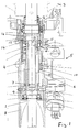
- the motor vehicle steering system has a steering spindle 1, on the upper end of which the shaft 2 of a steering wheel 3 is detachably fastened.
- a sleeve 4 is mounted coaxially on the steering spindle 1 and is axially movable on the steering spindle 1 by means of a steering lock 5.
- a feather key 6 Between the sleeve 4 and the steering spindle 1 is a feather key 6, which ensures that, despite the longitudinal displaceability of the sleeve 4, the latter is held on the steering spindle 1 in a rotationally fixed manner.
- the sleeve 4 assumes the lower position shown in FIG. 1, in which the lower end of the sleeve 4 with projections, in particular claws or teeth 7, rests in a rotationally fixed manner in corresponding recesses in the steering housing 8 or in a part 9 connected to the housing, so that the steering spindle 1 is locked against rotation in this position.
- the sleeve 4 is raised by an arm 10 of the steering lock 5, so that projections 11 or teeth or claws arranged in recesses 12 of the shaft are arranged at the upper end of the sleeve 4 2 form-fit to insert, whereby the steering wheel 3 is rotatably connected to the steering shaft 1.
- the parts 11, 12 thus form a first releasable coupling 13 which ensures that the steering wheel 3 is no longer connected to the steering spindle 1 when the key is removed and the parts are connected to one another when the key is inserted in the driving position of the key.
- a second clutch is provided, which in the exemplary embodiment according to FIG 14 is formed.
- This axially parallel detent spring engages with its front hemisphere End 15 into a lateral, axially parallel groove in the middle of shaft 2, groove 16 and end 15 forming a releasable limit force lock or a form lock, so that when the key is removed and the first clutch is uncoupled, the steering wheel 3 is still connected to the steering shaft 1 is connected until an unacceptably large force is exerted on the steering wheel 3. If this predetermined maximum permissible torque is exceeded, the steering wheel 3 is rotated relative to the steering spindle 1, so that the lock of the steering spindle 1 cannot be overcome by the steering wheel 3.
- the second coupling is formed by a spring-loaded ball 20, which is mounted in a transverse bore in the center of the shaft 2, the helical compression spring 22 generating the spring pressure being inserted into the transverse bore 21.
- the sleeve 4 engages over the transverse bore 21 and has a longitudinal groove 23 at the level of the ball 20, in which the ball 20 engages and remains therein until an impermissibly high torque is exerted on the steering wheel 3.
- Fig. 3 the key withdrawal position is shown.
- the projections 11 or teeth are only with their ends in the recesses 12 of the steering wheel shaft 2, so that when the steering wheel 3 is turned violently, the inclined surfaces 30 on the tooth ends and / or on the recess front sides exert axial forces on the sleeve 4, which the sleeve 4 axially against the pressure of Move disc springs 31 so that the steering wheel is free.
- part of the steering wheel shaft 2 in the form of a sleeve 32 can also yield axially upwards and differ from the pressure of disc springs 33 (FIG. 4).
- a fourth embodiment not shown, has a friction clutch as the second clutch, which ensures that when the first clutch is disengaged, the steering wheel is still rotationally connected via the friction with the steering spindle, but if an inadmissibly large force is exerted on the steering wheel, the steering wheel becomes locked against the locked steering spindle can twist.
- a friction clutch Reibgehemme
- a locking device can be arranged, which ensures that the correct rotational position of the steering wheel relative to the steering shaft can be easily found again if the steering wheel was rotated against the steering shaft.
Landscapes
- Engineering & Computer Science (AREA)
- Mechanical Engineering (AREA)
- Lock And Its Accessories (AREA)
- Transmission And Conversion Of Sensor Element Output (AREA)
- Mechanical Operated Clutches (AREA)
Applications Claiming Priority (2)
| Application Number | Priority Date | Filing Date | Title |
|---|---|---|---|
| DE4236701 | 1992-10-30 | ||
| DE4236701A DE4236701C1 (de) | 1992-10-30 | 1992-10-30 | Lenkung für ein Kraftfahrzeug |
Publications (2)
| Publication Number | Publication Date |
|---|---|
| EP0594980A1 true EP0594980A1 (fr) | 1994-05-04 |
| EP0594980B1 EP0594980B1 (fr) | 1996-02-07 |
Family
ID=6471749
Family Applications (1)
| Application Number | Title | Priority Date | Filing Date |
|---|---|---|---|
| EP93113968A Expired - Lifetime EP0594980B1 (fr) | 1992-10-30 | 1993-09-01 | Direction pour véhicule automobile |
Country Status (3)
| Country | Link |
|---|---|
| EP (1) | EP0594980B1 (fr) |
| DE (2) | DE4236701C1 (fr) |
| ES (1) | ES2088202T3 (fr) |
Families Citing this family (2)
| Publication number | Priority date | Publication date | Assignee | Title |
|---|---|---|---|---|
| SE9900191L (sv) * | 1998-09-01 | 2000-03-02 | Sten Aasen | Anordning inrättad att förhindra stöld av en farkost som är framdrivbar i vatten |
| US9029085B2 (en) | 2007-03-07 | 2015-05-12 | President And Fellows Of Harvard College | Assays and other reactions involving droplets |
Citations (2)
| Publication number | Priority date | Publication date | Assignee | Title |
|---|---|---|---|---|
| US3566634A (en) * | 1968-11-07 | 1971-03-02 | Borg Warner | Steering column lock-free wheeling |
| EP0336881A2 (fr) * | 1988-04-02 | 1989-10-11 | Dieter Oelkers | Dispositif pour verrouiller la direction d'un véhicule automobile |
Family Cites Families (2)
| Publication number | Priority date | Publication date | Assignee | Title |
|---|---|---|---|---|
| BR8200448A (pt) * | 1981-02-06 | 1982-11-30 | Ignacio Diaz | Dispositivo aperfeicoado contra roubo para automovel |
| DE3435084A1 (de) * | 1984-09-25 | 1986-04-03 | Daimler-Benz Ag, 7000 Stuttgart | Lenkschloss fuer kraftfahrzeuge |
-
1992
- 1992-10-30 DE DE4236701A patent/DE4236701C1/de not_active Expired - Fee Related
-
1993
- 1993-09-01 ES ES93113968T patent/ES2088202T3/es not_active Expired - Lifetime
- 1993-09-01 DE DE59301591T patent/DE59301591D1/de not_active Expired - Fee Related
- 1993-09-01 EP EP93113968A patent/EP0594980B1/fr not_active Expired - Lifetime
Patent Citations (2)
| Publication number | Priority date | Publication date | Assignee | Title |
|---|---|---|---|---|
| US3566634A (en) * | 1968-11-07 | 1971-03-02 | Borg Warner | Steering column lock-free wheeling |
| EP0336881A2 (fr) * | 1988-04-02 | 1989-10-11 | Dieter Oelkers | Dispositif pour verrouiller la direction d'un véhicule automobile |
Also Published As
| Publication number | Publication date |
|---|---|
| EP0594980B1 (fr) | 1996-02-07 |
| DE4236701C1 (de) | 1994-04-07 |
| ES2088202T3 (es) | 1996-08-01 |
| DE59301591D1 (de) | 1996-03-21 |
Similar Documents
| Publication | Publication Date | Title |
|---|---|---|
| DE69922373T2 (de) | Verschlussvorrichtung und haubenschloss für ein fahrzeug mit einer derartigen verschlussvorrichtung | |
| DE60016521T2 (de) | Lenksperre mit Sicherheitsvorrichtung | |
| DE9208698U1 (de) | Lenkradschloß | |
| DE102008023759A1 (de) | Lenkvorrichtung für ein Kraftfahrzeug mit einem Lenkrad, einer Lenkwelle und einem Überlagerungsgetriebe | |
| DE3223778C2 (fr) | ||
| EP4192707A1 (fr) | Dispositif d'accouplement pour un module de stockage, module de stockage et véhicule à moteur | |
| DE112017007287T5 (de) | Einstelleinheit für das Strahlniveau einer Lichteinheit in einem Scheinwerfer | |
| AT392237B (de) | Diebstahlsicherungsvorrichtung fuer autos | |
| EP0594980B1 (fr) | Direction pour véhicule automobile | |
| DE2916559A1 (de) | Lenkwellen-verriegelungsvorrichtung | |
| DE102018203201A1 (de) | Antriebssperrbaugruppe sowie Kraftrad | |
| DE19906268C2 (de) | Vorrichtung zur elektrischen Verriegelung der Lenkspindel einer Lenkeinrichtung | |
| DE19848733A1 (de) | Vorrichtung zur Notentriegelung einer Sicherheitseinrichtung für ein Kraftfahrzeug mit einem Automatik-Getriebe | |
| DE3121916C2 (de) | Lenkradschloß für Kraftfahrzeuge | |
| DE3100905A1 (de) | Diebstahlsicherungsvorrichtung fuer fahrzeuge, insbesondere fahrraeder | |
| DE102022103378A1 (de) | Fahrzeugsitzbeschlag-Entriegelungsbaugruppe, Fahrzeugsitzbeschlag und Fahrzeugsitz | |
| DE102021209478A1 (de) | Gurtaufroller für einen Sicherheitsgurt | |
| DE102017214541B4 (de) | Lenksystem für ein Kraftfahrzeug | |
| DE2119255C3 (de) | Lenkschloß für Kraftfahrzeuge | |
| DE2605589C3 (de) | Kraftfahrzeug-Lenkschloß | |
| DE102020104597A1 (de) | Taumelgetriebe für Verstellvorrichtungen | |
| DE10052860A1 (de) | Ein Zünd/Start-Sperrsystem | |
| DE102024205702A1 (de) | Schaltvorrichtung für ein Fahrzeug mit einem Differential | |
| DE60302337T2 (de) | Entriegelungsvorrichtung für verriegelungseinrichtung für einen radbolzen | |
| DE2130810C3 (de) | Lenkschloß für Kraftfahrzeuge |
Legal Events
| Date | Code | Title | Description |
|---|---|---|---|
| PUAI | Public reference made under article 153(3) epc to a published international application that has entered the european phase |
Free format text: ORIGINAL CODE: 0009012 |
|
| AK | Designated contracting states |
Kind code of ref document: A1 Designated state(s): DE ES FR GB IT |
|
| 17P | Request for examination filed |
Effective date: 19940329 |
|
| 17Q | First examination report despatched |
Effective date: 19950418 |
|
| GRAA | (expected) grant |
Free format text: ORIGINAL CODE: 0009210 |
|
| AK | Designated contracting states |
Kind code of ref document: B1 Designated state(s): DE ES FR GB IT |
|
| GBT | Gb: translation of ep patent filed (gb section 77(6)(a)/1977) |
Effective date: 19960217 |
|
| REF | Corresponds to: |
Ref document number: 59301591 Country of ref document: DE Date of ref document: 19960321 |
|
| ET | Fr: translation filed | ||
| ITF | It: translation for a ep patent filed | ||
| REG | Reference to a national code |
Ref country code: ES Ref legal event code: BA2A Ref document number: 2088202 Country of ref document: ES Kind code of ref document: T3 |
|
| REG | Reference to a national code |
Ref country code: ES Ref legal event code: FG2A Ref document number: 2088202 Country of ref document: ES Kind code of ref document: T3 |
|
| PLBE | No opposition filed within time limit |
Free format text: ORIGINAL CODE: 0009261 |
|
| 26N | No opposition filed | ||
| PGFP | Annual fee paid to national office [announced via postgrant information from national office to epo] |
Ref country code: GB Payment date: 20010824 Year of fee payment: 9 |
|
| PGFP | Annual fee paid to national office [announced via postgrant information from national office to epo] |
Ref country code: ES Payment date: 20010912 Year of fee payment: 9 |
|
| PGFP | Annual fee paid to national office [announced via postgrant information from national office to epo] |
Ref country code: DE Payment date: 20010920 Year of fee payment: 9 |
|
| PGFP | Annual fee paid to national office [announced via postgrant information from national office to epo] |
Ref country code: FR Payment date: 20010928 Year of fee payment: 9 |
|
| REG | Reference to a national code |
Ref country code: GB Ref legal event code: IF02 |
|
| PG25 | Lapsed in a contracting state [announced via postgrant information from national office to epo] |
Ref country code: GB Free format text: LAPSE BECAUSE OF NON-PAYMENT OF DUE FEES Effective date: 20020901 |
|
| PG25 | Lapsed in a contracting state [announced via postgrant information from national office to epo] |
Ref country code: ES Free format text: LAPSE BECAUSE OF NON-PAYMENT OF DUE FEES Effective date: 20020902 |
|
| PG25 | Lapsed in a contracting state [announced via postgrant information from national office to epo] |
Ref country code: DE Free format text: LAPSE BECAUSE OF NON-PAYMENT OF DUE FEES Effective date: 20030401 |
|
| GBPC | Gb: european patent ceased through non-payment of renewal fee |
Effective date: 20020901 |
|
| PG25 | Lapsed in a contracting state [announced via postgrant information from national office to epo] |
Ref country code: FR Free format text: LAPSE BECAUSE OF NON-PAYMENT OF DUE FEES Effective date: 20030603 |
|
| REG | Reference to a national code |
Ref country code: FR Ref legal event code: ST |
|
| REG | Reference to a national code |
Ref country code: ES Ref legal event code: FD2A Effective date: 20031011 |
|
| PG25 | Lapsed in a contracting state [announced via postgrant information from national office to epo] |
Ref country code: IT Free format text: LAPSE BECAUSE OF NON-PAYMENT OF DUE FEES;WARNING: LAPSES OF ITALIAN PATENTS WITH EFFECTIVE DATE BEFORE 2007 MAY HAVE OCCURRED AT ANY TIME BEFORE 2007. THE CORRECT EFFECTIVE DATE MAY BE DIFFERENT FROM THE ONE RECORDED. Effective date: 20050901 |