EP0595028A2 - Procédé de surveillance d'un terrain - Google Patents
Procédé de surveillance d'un terrain Download PDFInfo
- Publication number
- EP0595028A2 EP0595028A2 EP93115409A EP93115409A EP0595028A2 EP 0595028 A2 EP0595028 A2 EP 0595028A2 EP 93115409 A EP93115409 A EP 93115409A EP 93115409 A EP93115409 A EP 93115409A EP 0595028 A2 EP0595028 A2 EP 0595028A2
- Authority
- EP
- European Patent Office
- Prior art keywords
- measuring
- earth resistance
- probes
- probe
- measurement
- Prior art date
- Legal status (The legal status is an assumption and is not a legal conclusion. Google has not performed a legal analysis and makes no representation as to the accuracy of the status listed.)
- Granted
Links
Images




Classifications
-
- G—PHYSICS
- G01—MEASURING; TESTING
- G01V—GEOPHYSICS; GRAVITATIONAL MEASUREMENTS; DETECTING MASSES OR OBJECTS; TAGS
- G01V3/00—Electric or magnetic prospecting or detecting; Measuring magnetic field characteristics of the earth, e.g. declination, deviation
- G01V3/02—Electric or magnetic prospecting or detecting; Measuring magnetic field characteristics of the earth, e.g. declination, deviation operating with propagation of electric current
Definitions
- the invention relates to a method for monitoring an area according to the preamble of claim 1.
- the determination of the potentials can be especially in the case of dynamic changes in the underground, such as B. in artificial fractions, good results.
- the rock is broken by hydraulic pressure, seismic or seismic-acoustic events and electrical conductivity changes occur.
- filtration potentials and potentials are generated due to geochemical changes in the drilling fluid due to the liquid or steam injection into the rock formation under high pressure and in a short time.
- an electrolyte is pressed through the rock capillary, which acts like a diaphragm.
- the electrochemical double layer originally existing at the solid / liquid interface is consequently broken down into a stationary adhesive and a non-stationary diffusive part. The result is a potential difference due to the electrical charges located between the ends of the capillaries.
- EP 477 167 discloses a method for monitoring an area, in which the potential is measured by means of probes at several measuring points in the area and converted into electrical signals, the signals being queried and processed by a central computer unit at predetermined time intervals.
- the measuring points are arranged at predetermined intervals along a closed line enclosing the area.
- some measuring points are provided below the area.
- a method for finding and researching usable deposits in the ground is known with the aid of self-potential measurements, wherein after measuring the self-potential of the soil to be examined, a current conductor with a high, controllable resistance is connected in parallel to the input of the potential measuring device. The value of the resistance is determined at which the potential of the ground drops to a fraction of the potential value measured without current consumption when the resistor is switched on.
- a method for determining the earth resistance in connection with potential measurements is also known from DE 392 189.
- DE 35 29 466 describes a method for determining the boundaries of underground deposits filled with hydrocarbons, in which measuring probes are arranged in a grid and intrinsic potential curves are determined.
- the invention has for its object to provide a method for monitoring an area with the help of a self-potential measurement, in which the influence of telluric currents is largely excluded and high accuracy and reliability of the results obtained can be achieved.
- the method according to the invention is characterized in particular in that, in addition to determining the potentials on the individual measuring probes, the earth resistance between the same measuring probe and base probe is determined immediately before or after a measurement. It is therefore not only the value of the intrinsic potential that is used for the evaluation, but in particular the value of the flowing currents, which results from the intrinsic potential measurement taking into account the earth resistance.
- the measuring probes are preferably arranged in groups lying parallel to one another along measuring lines.
- each group contains 16 measuring probes and there are a total of 16 groups, so that there is a total of 256 measuring probes.
- a memory unit is assigned to each group of measuring probes, in which the simultaneously acquired potential values of the measuring probes of the associated group are temporarily stored. All measuring probes of the entire grid are queried at the same time, so that 16 measuring values are available at the same time in each storage unit and are temporarily stored. These temporarily stored values are then cyclically transferred to a central unit. This allows the state of the potential of all of the measuring probes to be determined at a single point in time. The measurement data can then be transmitted to the central unit cyclically between two successive measurements.
- the earth resistance is measured before or after each measurement of the inherent potentials. This results in a close chronological assignment of the potential measurement to the earth resistance measurement.
- the earth resistance is not measured simultaneously with the measurement of the intrinsic potential, but the changes in the earth resistance over time are generally smaller than the changes in the potential values within the period under consideration.
- the earth resistance is also measured with the aid of the measuring probes, and the results are transferred to the storage units and buffered in the same way as the potential values. They can then be cyclically transferred to the central unit. To a high measuring cycle time To achieve, it can also be provided that the earth resistance measurement is carried out only after a larger number of potential measurements.
- the determined natural potentials of the measuring probes are preferably transferred analogously to the associated storage units of a group. This makes it possible to avoid analog-digital converters on each individual probe.
- Central filters for example low-pass filters, can also be used in a storage unit. The filtering can also be carried out in the digital area after the intermediate storage.
- the measured values of the earth resistance measurement are also transferred analog to the associated memory unit and cyclically transferred to the central unit after analog-digital conversion.
- the cyclic transmission of the natural potential values or earth resistance values from the storage units to the central unit is preferably carried out digitally using the time-division multiplex method.
- the query time of a group of measuring probes is preferably 0.5 msec.
- the cyclic transmission of the data from the storage units to the central unit takes place in a time below 10 seconds, for example in 2 seconds.
- a reference voltage is preferably applied between the base probe and the respective measuring probes. The voltage drop across a measuring resistor is determined and the earth resistance is calculated from this.
- the measuring probes are in particular non-polarizable probes.
- the determined natural potentials are evaluated with the determined earth resistance and shown in the form of isolines on a map showing the area.
- the absolute potential values at the individual measuring probes are not used for switching off telluric currents, but rather differential potentials between neighboring measuring probes.
- the invention permits the highly precise determination of the intrinsic potential distribution over an area at precisely determinable times with extensive elimination of interference signals and changes in earth resistance.
- Fig. 1 shows an area with the edges 1, 2 with an above-ground measuring arrangement.
- a drill string 4 leads from a drilling rig 3 into an oil-bearing sandstone in which the sandstone is to be broken up in a fracturing area 5.
- the number 6 indicates the vertical projection of the fracture point on the surface.
- a central computer control with a central unit and evaluation devices is accommodated in a measuring carriage 7.
- 16 storage units are arranged at the same distance from one another along a telemetry cable 9, the first storage unit being designated by the number 8 and the last storage unit being designated by the number 10.
- a line 11 is connected to the storage unit 10 and also to every other storage unit, which leads to the individual measuring probes 12, a total of 16 probes being arranged along the line 11.
- the entire measurement grid therefore contains 256 probes.
- a base probe 13 is arranged outside the measuring grid and is also connected to the measuring carriage.
- a current is fed in between the base probe and individual measurement probes, while the potential measurement between the base probe and measurement probes is carried out without voltage.
- FIG. 2 shows a usable computer system.
- a line 11 is shown, to which 16 measuring probes 12 are connected.
- the line 11 leads to a memory unit 8.
- This contains in particular a 16-channel preamplifier with an analog filter 14, subsequently a 12-bit analog-digital converter, a microprocessor 16 and a power supply unit 17.
- the signal filtering is preferably carried out in the analog range, separately for each individual measuring probe. However, it is also possible to carry out the filtering at least in part on the digital signal.
- the determined data of the 16 measuring probes are temporarily stored in the memory unit 8 and are available for query by the central computer.
- a control unit 18 for earth resistance measurement is provided in the central computer. Furthermore, the data queried by the storage units 8 are transmitted to the control computer 20 via an RS232 / 485 converter 19 and can be stored on a hard disk 21. A floppy disc 22 and a power supply unit 23 are also provided. The results of the measurements can be printed out on a printer 24.
- the computer is operated via a keyboard 25. Furthermore, a monitor 26 is provided for displaying measurement results or for controlling the computer.
- Fig. 3 shows a usable measuring probe.
- a hollow ceramic housing 27 is provided, which is partially filled with copper sulfate solution 28.
- Faulty copper sulfate 32 is present at the lower end of the housing.
- a copper rod 29 is inserted into the copper sulfate solution 28 and is held at the upper end of the ceramic housing by a rubber stopper 30.
- the measuring probe is connected to line 11 via a connecting cable 31.
- FIG. 4 shows a basic illustration of a storage unit.
- the individual measuring probes are connected to an analog-digital converter 40 via their own preamplifiers 39 and filters 41.
- the outputs of all the analog-digital converters in a group lead to a sample & hold storage unit 42, which temporarily stores the data. From here, they are transferred cyclically to the central computer 44 via a multiplex query 43 and displayed on the display unit 45.
- Fig. 5 shows the principle of earth resistance measurement.
- a DC voltage source 33 is provided, the circuit of which is via the base electrode 13, the earth resistor 35, a measuring probe 36, a switch 37 and a measuring resistor 38 leads.
- the switch 37 is closed during the earth resistance measurement.
- the voltage drop across the measuring resistor 38 is amplified via the amplifier 39 and conducted to the analog-digital converter 40 in the same way as the potential measurement data of the probe.
- the switch 34 is closed and the switch 46 is open.
- the switch 37 is open during a measurement of the potentials.
- the potential difference between base electrode 13 and measuring probe 36 is determined in this way between the amplifier connection of amplifier 39 and ground.
- the potentials determined can be evaluated immediately, but it is preferred to use potential differences between adjacent probes for the evaluation in order to eliminate telluric currents in the background from the measurement. It is assumed that the telluric currents essentially act in the same way on all measuring probes at the same time.
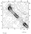
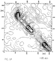
- FIG. 6A shows the representation of an area with the dimensions 200 ⁇ 200 m before a fracturing process is carried out. A disturbed probe is present at position 47. The representation does not show a preferred distribution of the determined potential values.
- 6B shows the state of the potential distribution about 15 minutes after the start of the fracturing process.
- 6C shows the state after 20 minutes, an alignment of changed potential values from the top left to the bottom right already being recognizable.
- FIG. 6D After 25 minutes there is a pronounced orientation of the potential values which lasts for up to 85 minutes (FIGS. 6E, 6F). After 90 minutes (FIG. 6G), the display changes again in the direction of its original state (FIG. 6H).
- the invention can not only be used for exploring fracture directions and dimensions, but is also suitable for exploring Ore deposits, for examining dams and dikes for leaks, for contouring contaminated groundwater in the downstream area of and in landfills, for exploring contamination sources in soils, for determining the gas / salt water contact of gas reservoirs and other underground events that influence the potential values on the surface.
- results can be extracted from the determined data, since all the data are stored in digital form.
- static parameters such as mean value, scatter, standard deviation (for each probe), contraction of potential anomalies, etc. can be determined.
- individual probe profiles can be selected from the overall measurement configuration. Different interpolation methods allow grid generation.
- the representation can be made in the form of isoline maps or 3D representations.
- the display can be carried out both in real time and subsequently.
- results can be standardized to specific probes, specific times or specific potential values. Basically there are no limits to the evaluation options.
Landscapes
- Life Sciences & Earth Sciences (AREA)
- Engineering & Computer Science (AREA)
- Environmental & Geological Engineering (AREA)
- Geology (AREA)
- Remote Sensing (AREA)
- Physics & Mathematics (AREA)
- General Life Sciences & Earth Sciences (AREA)
- General Physics & Mathematics (AREA)
- Geophysics (AREA)
- Geophysics And Detection Of Objects (AREA)
- Investigating Or Analyzing Materials By The Use Of Electric Means (AREA)
Applications Claiming Priority (2)
| Application Number | Priority Date | Filing Date | Title |
|---|---|---|---|
| DE4235963A DE4235963C1 (de) | 1992-10-26 | 1992-10-26 | Verfahren zur Überwachung eines Gebietes |
| DE4235963 | 1992-10-26 |
Publications (3)
| Publication Number | Publication Date |
|---|---|
| EP0595028A2 true EP0595028A2 (fr) | 1994-05-04 |
| EP0595028A3 EP0595028A3 (fr) | 1994-10-26 |
| EP0595028B1 EP0595028B1 (fr) | 1997-07-16 |
Family
ID=6471272
Family Applications (1)
| Application Number | Title | Priority Date | Filing Date |
|---|---|---|---|
| EP93115409A Expired - Lifetime EP0595028B1 (fr) | 1992-10-26 | 1993-09-24 | Procédé géophysique de surveillance d'un terrain |
Country Status (4)
| Country | Link |
|---|---|
| US (1) | US5514963A (fr) |
| EP (1) | EP0595028B1 (fr) |
| CA (1) | CA2108067A1 (fr) |
| DE (2) | DE4235963C1 (fr) |
Cited By (3)
| Publication number | Priority date | Publication date | Assignee | Title |
|---|---|---|---|---|
| GB2283099B (en) * | 1993-06-03 | 1997-11-26 | Apex Data Systems Ltd | Method and apparatus for measuring geophysical data |
| DE102014222274A1 (de) | 2014-10-31 | 2016-05-04 | Rheinisch-Westfälisch-Technische Hochschule Aachen | System zur nicht-invasiven Überwachung von Untergrundspeichern und Verfahren zur Detektion von Leckagen in Untergrundspeichern |
| CN106950889A (zh) * | 2017-04-27 | 2017-07-14 | 中南大学 | 一种自然电场无线传感器及自动化地下污染监控系统 |
Families Citing this family (18)
| Publication number | Priority date | Publication date | Assignee | Title |
|---|---|---|---|---|
| WO1994029752A1 (fr) * | 1993-06-03 | 1994-12-22 | Apex Data Systems Limited | Procede et appareil de mesure de donnees geophysiques |
| DE19709889C1 (de) * | 1997-03-11 | 1998-07-02 | Umweltanalytik Brandenburg Gmb | Anordnung zur computergestützten Durchführung geophysikalischer Messungen in wasserbedeckten Gebieten und wasserdichte nicht polarisierbare Elektrode hierfür |
| DE19913220C2 (de) * | 1999-03-24 | 2001-07-05 | Gsf Forschungszentrum Umwelt | Verfahren zur Detektion von Spurenstoffen und/oder Umgebungseigenschaften |
| US7390086B2 (en) * | 2002-05-24 | 2008-06-24 | Lee Jung I | Clip on eyeware with insertable member |
| US7498818B2 (en) * | 2006-08-25 | 2009-03-03 | Schweitzer Engineering Laboratories, Inc. | Apparatus and method for detecting a brush liftoff in a synchronous generator rotor circuit |
| US8405940B2 (en) * | 2009-10-13 | 2013-03-26 | Schweitzer Engineering Laboratories Inc | Systems and methods for generator ground fault protection |
| KR101131826B1 (ko) | 2009-10-29 | 2012-03-30 | 한국지질자원연구원 | 센서 네트워크 기반의 전기비저항 탐사 시스템 |
| WO2011117704A2 (fr) | 2010-03-22 | 2011-09-29 | Council Of Scientific & Industrial Research | Système de balayage du champ d'auto-potentiel de la terre |
| US10288688B2 (en) | 2014-07-24 | 2019-05-14 | Schweitzer Engineering Laboratories, Inc. | Systems and methods for monitoring and protecting an electric power generator |
| US9496707B2 (en) | 2014-12-22 | 2016-11-15 | Schweitzer Engineering Laboratories, Inc. | Generator protection element |
| US10931097B2 (en) | 2017-09-25 | 2021-02-23 | Schweitzer Engineering Laboratories, Inc. | Generator stator ground protection using third harmonic |
| US10333291B2 (en) | 2017-09-25 | 2019-06-25 | Schweitzer Engineering Laboratories, Inc. | Multiple generator ground fault detection |
| US10797632B2 (en) | 2018-08-21 | 2020-10-06 | Schweitzer Engineering Laboratories, Inc. | Sensitive directional element for generator protection |
| US11316455B2 (en) | 2019-08-28 | 2022-04-26 | Schweitzer Engineering Laboratories, Inc. | Generator rotor turn-to-turn fault detection using fractional harmonics |
| US10819261B1 (en) | 2019-10-25 | 2020-10-27 | Schweitzer Engineering Laboratories, Inc. | Security improvements for electric power generator protection |
| US11631972B2 (en) | 2020-12-16 | 2023-04-18 | Schweitzer Engineering Laboratories, Inc. | Accurate modeling of equipment overexcitation damage curves |
| US12249948B2 (en) | 2022-08-30 | 2025-03-11 | Schweitzer Engineering Laboratories, Inc. | Split-phase protection of generators |
| US11946966B1 (en) | 2023-02-20 | 2024-04-02 | Schweitzer Engineering Laboratories, Inc. | Selective stator ground fault protection using positive-sequence voltage reference |
Family Cites Families (14)
| Publication number | Priority date | Publication date | Assignee | Title |
|---|---|---|---|---|
| DE392189C (de) * | 1921-12-13 | 1924-03-17 | Erda Akt Ges | Verfahren zur Ergaenzung von Messungen mittels AEquipotentiallinienmethode fuer Erderforschungszwecke |
| US2917704A (en) * | 1954-05-24 | 1959-12-15 | Jan J Arps | Earth formation logging system |
| DE962105C (de) * | 1955-11-10 | 1957-04-18 | Seismos G M B H | Verfahren zum Auffinden und Erforschen nutzbarer Lagerstaetten im Erdboden mit Hilfe von Eigenpotentialmessungen |
| GB1375412A (fr) * | 1971-03-09 | 1974-11-27 | ||
| US4296379A (en) * | 1977-08-25 | 1981-10-20 | Eizaburo Yoshizumi | Ground prospecting method utilizing electrical resistivity measurements for measuring the resistivity of unit blocks of the ground |
| GB8500390D0 (en) * | 1985-01-08 | 1985-02-13 | Univ Birmingham | Resistivity surveying apparatus |
| DE3529466A1 (de) * | 1985-08-16 | 1987-04-09 | Pipeline Engineering Ges Fuer | Verfahren zur bestimmung der grenzen von unterirdischen erdgas-lagerstaetten |
| US4804906A (en) * | 1987-02-05 | 1989-02-14 | Chevron Research Company | Method and apparatus for well casing inspection |
| US4875015A (en) * | 1987-07-20 | 1989-10-17 | University Of Utah Research Institute | Multi-array borehole resistivity and induced polarization method with mathematical inversion of redundant data |
| DE3738867A1 (de) * | 1987-11-06 | 1989-06-08 | Siemens Ag | Messgeraet zur bestimmung des ableit-, erdableit- und standortuebergangswiderstandes |
| DE3874756T2 (de) * | 1988-11-22 | 1993-04-08 | D Electronique Appliquee B E A | Geraet und verfahren zur elektrischen untergrunduntersuchung. |
| IL99506A0 (en) * | 1990-09-17 | 1992-08-18 | Proterra Umwelttechnik | Method and arrangement for the monitoring of premises |
| US5200705A (en) * | 1991-10-31 | 1993-04-06 | Schlumberger Technology Corporation | Dipmeter apparatus and method using transducer array having longitudinally spaced transducers |
| DE9203755U1 (de) * | 1992-03-20 | 1992-07-30 | Nemes, Istvan, Dipl.-Geophys., 3167 Burgdorf | Schaltereinheit für die Abfrage von Spannungen räumlich verteilter Spannungsquellen |
-
1992
- 1992-10-26 DE DE4235963A patent/DE4235963C1/de not_active Expired - Fee Related
-
1993
- 1993-09-24 EP EP93115409A patent/EP0595028B1/fr not_active Expired - Lifetime
- 1993-09-24 DE DE59306925T patent/DE59306925D1/de not_active Expired - Fee Related
- 1993-10-08 CA CA002108067A patent/CA2108067A1/fr not_active Abandoned
- 1993-10-14 US US08/137,287 patent/US5514963A/en not_active Expired - Fee Related
Cited By (4)
| Publication number | Priority date | Publication date | Assignee | Title |
|---|---|---|---|---|
| GB2283099B (en) * | 1993-06-03 | 1997-11-26 | Apex Data Systems Ltd | Method and apparatus for measuring geophysical data |
| DE102014222274A1 (de) | 2014-10-31 | 2016-05-04 | Rheinisch-Westfälisch-Technische Hochschule Aachen | System zur nicht-invasiven Überwachung von Untergrundspeichern und Verfahren zur Detektion von Leckagen in Untergrundspeichern |
| DE102014222274B4 (de) * | 2014-10-31 | 2016-06-30 | Rheinisch-Westfälisch-Technische Hochschule Aachen | Verfahren und Vorrichtung zur Erfassung von unterirdischen Fluidströmungen in Untergrundspeichern |
| CN106950889A (zh) * | 2017-04-27 | 2017-07-14 | 中南大学 | 一种自然电场无线传感器及自动化地下污染监控系统 |
Also Published As
| Publication number | Publication date |
|---|---|
| CA2108067A1 (fr) | 1994-04-27 |
| DE59306925D1 (de) | 1997-08-21 |
| EP0595028A3 (fr) | 1994-10-26 |
| US5514963A (en) | 1996-05-07 |
| DE4235963C1 (de) | 1994-03-31 |
| EP0595028B1 (fr) | 1997-07-16 |
Similar Documents
| Publication | Publication Date | Title |
|---|---|---|
| EP0595028B1 (fr) | Procédé géophysique de surveillance d'un terrain | |
| DE69015778T2 (de) | Verfahren und Gerät zur Spontanpotential-Bohrlochmessung. | |
| EP0212275B1 (fr) | Procédé pour déterminer les limites des couches de gaz naturel souterrain | |
| DE1953165A1 (de) | Bohrlochpruefgeraet zum Messen der Charakteristiken von Erdformationen und Verfahren zu dessen Benutzung | |
| DE69612406T2 (de) | Feststellung der Porosität und Permeabilität einer geologischen Formation, basiert auf das Elektrofiltrationsphänomen | |
| DE60003307T9 (de) | Ein verfahren und eine vorrichtung zur bestimmung eines formationswiderstandes, durch welchen ein verrohrtes bohrloch führt | |
| DE2941104A1 (de) | Verfahren und vorrichtung zum untersuchen von erdbohrloechern | |
| DE2718396A1 (de) | Verfahren zur in-situ-bestimmung des muttergestein-lagerstaettenpotentials von gesteinsschichten | |
| DD152637A5 (de) | Verfahren zur prospektion von erdgas-und erdoellagerstaetten | |
| DE69515295T2 (de) | Flüssigkeitsnachweisvorrichtung | |
| DE60003308T2 (de) | Verfahren zur bestimmung eines widerstandes einer formation durch welche ein verrohrtes bohrloch führt | |
| DE1498009A1 (de) | Mit mehreren Empfaengern arbeitendes Akustiklog | |
| DE2057632B2 (de) | Verfahren und vorrichtung zur bestimmung des spontanen potentials von erdformationen | |
| DE3716846A1 (de) | Verfahren zur ueberwachung von gebieten, insbesondere muelldeponien, daemmen, deichen oder dergleichen | |
| DE102014222274B4 (de) | Verfahren und Vorrichtung zur Erfassung von unterirdischen Fluidströmungen in Untergrundspeichern | |
| DE69408690T2 (de) | Verfahren und geraet zum messen von geophysikalischen daten | |
| DE4313773C1 (de) | Verfahren zur Überwachung eines Gebietes mittels Fremdpotentialmessung | |
| DE3874756T2 (de) | Geraet und verfahren zur elektrischen untergrunduntersuchung. | |
| DE19914658A1 (de) | Anordnung zur Messung von Undichtigkeiten in Abdichtungssystemen zur Leckagedetektion und Leckageortung elektrisch leitender Fluide sowie Verwendung einer solchen Anordnung | |
| DE898785C (de) | Verfahren und Vorrichtung zur Bestimmung der von einem Bohrloch durchschlagenen Bodenschichten | |
| DE19532605A1 (de) | Verfahren zum Erkunden von geplanten Tunnelstrecken | |
| DE102018124090A1 (de) | Elektronische Schaltung für einen elektrochemischen Sensor und Verfahren zur Messung einer Impedanz von mindestens einem Messkanal des elektrochemischen Sensors | |
| Weber | Quantitative Ableitung sedimentphysikalischer Parameter mit Hilfe eines Multi-Sensor Core Loggers neue Wege in der Analytik mariner Sedimente | |
| DE102018124092A1 (de) | Elektronische Schaltung für einen elektrochemischen Sensor und Verfahren zur Funktionsanalyse des elektrochemischen Sensors | |
| DE1548155C3 (de) | Geoelektrische Bohrloch- MeBlog-Apparatur |
Legal Events
| Date | Code | Title | Description |
|---|---|---|---|
| PUAI | Public reference made under article 153(3) epc to a published international application that has entered the european phase |
Free format text: ORIGINAL CODE: 0009012 |
|
| AK | Designated contracting states |
Kind code of ref document: A2 Designated state(s): BE DE FR GB IT LU NL |
|
| PUAL | Search report despatched |
Free format text: ORIGINAL CODE: 0009013 |
|
| AK | Designated contracting states |
Kind code of ref document: A3 Designated state(s): BE DE FR GB IT LU NL |
|
| 17P | Request for examination filed |
Effective date: 19950323 |
|
| 17Q | First examination report despatched |
Effective date: 19960412 |
|
| GRAG | Despatch of communication of intention to grant |
Free format text: ORIGINAL CODE: EPIDOS AGRA |
|
| GRAH | Despatch of communication of intention to grant a patent |
Free format text: ORIGINAL CODE: EPIDOS IGRA |
|
| GRAH | Despatch of communication of intention to grant a patent |
Free format text: ORIGINAL CODE: EPIDOS IGRA |
|
| GRAA | (expected) grant |
Free format text: ORIGINAL CODE: 0009210 |
|
| AK | Designated contracting states |
Kind code of ref document: B1 Designated state(s): BE DE FR GB IT LU NL |
|
| PG25 | Lapsed in a contracting state [announced via postgrant information from national office to epo] |
Ref country code: NL Free format text: LAPSE BECAUSE OF FAILURE TO SUBMIT A TRANSLATION OF THE DESCRIPTION OR TO PAY THE FEE WITHIN THE PRESCRIBED TIME-LIMIT Effective date: 19970716 Ref country code: IT Free format text: LAPSE BECAUSE OF FAILURE TO SUBMIT A TRANSLATION OF THE DESCRIPTION OR TO PAY THE FEE WITHIN THE PRE;WARNING: LAPSES OF ITALIAN PATENTS WITH EFFECTIVE DATE BEFORE 2007 MAY HAVE OCCURRED AT ANY TIME BEFORE 2007. THE CORRECT EFFECTIVE DATE MAY BE DIFFERENT FROM THE ONE RECORDED.SCRIBED TIME-LIMIT Effective date: 19970716 Ref country code: GB Effective date: 19970716 Ref country code: FR Effective date: 19970716 |
|
| REF | Corresponds to: |
Ref document number: 59306925 Country of ref document: DE Date of ref document: 19970821 |
|
| PG25 | Lapsed in a contracting state [announced via postgrant information from national office to epo] |
Ref country code: LU Free format text: LAPSE BECAUSE OF NON-PAYMENT OF DUE FEES Effective date: 19970930 Ref country code: BE Free format text: LAPSE BECAUSE OF NON-PAYMENT OF DUE FEES Effective date: 19970930 |
|
| NLV1 | Nl: lapsed or annulled due to failure to fulfill the requirements of art. 29p and 29m of the patents act | ||
| EN | Fr: translation not filed | ||
| GBV | Gb: ep patent (uk) treated as always having been void in accordance with gb section 77(7)/1977 [no translation filed] |
Effective date: 19970716 |
|
| BERE | Be: lapsed |
Owner name: PRAKLA-SEISMOS G.M.B.H. Effective date: 19970930 |
|
| PLBE | No opposition filed within time limit |
Free format text: ORIGINAL CODE: 0009261 |
|
| PG25 | Lapsed in a contracting state [announced via postgrant information from national office to epo] |
Ref country code: DE Free format text: LAPSE BECAUSE OF NON-PAYMENT OF DUE FEES Effective date: 19980603 |
|
| 26N | No opposition filed |