EP0595097A1 - Automatisches Schmiersystem - Google Patents
Automatisches Schmiersystem Download PDFInfo
- Publication number
- EP0595097A1 EP0595097A1 EP93116418A EP93116418A EP0595097A1 EP 0595097 A1 EP0595097 A1 EP 0595097A1 EP 93116418 A EP93116418 A EP 93116418A EP 93116418 A EP93116418 A EP 93116418A EP 0595097 A1 EP0595097 A1 EP 0595097A1
- Authority
- EP
- European Patent Office
- Prior art keywords
- grease
- pump
- pipes
- greasing
- timer
- Prior art date
- Legal status (The legal status is an assumption and is not a legal conclusion. Google has not performed a legal analysis and makes no representation as to the accuracy of the status listed.)
- Withdrawn
Links
- 239000004519 grease Substances 0.000 claims abstract description 28
- 238000010438 heat treatment Methods 0.000 claims abstract description 14
- 238000005461 lubrication Methods 0.000 description 7
- 239000012530 fluid Substances 0.000 description 3
- 239000004952 Polyamide Substances 0.000 description 1
- 229910000831 Steel Inorganic materials 0.000 description 1
- 238000007664 blowing Methods 0.000 description 1
- 230000002045 lasting effect Effects 0.000 description 1
- 239000007788 liquid Substances 0.000 description 1
- 239000000314 lubricant Substances 0.000 description 1
- 239000002184 metal Substances 0.000 description 1
- 239000003921 oil Substances 0.000 description 1
- 229920002647 polyamide Polymers 0.000 description 1
- 229920002635 polyurethane Polymers 0.000 description 1
- 239000004814 polyurethane Substances 0.000 description 1
- 238000005086 pumping Methods 0.000 description 1
- 230000009467 reduction Effects 0.000 description 1
- 238000007789 sealing Methods 0.000 description 1
- 230000011664 signaling Effects 0.000 description 1
- 239000010959 steel Substances 0.000 description 1
- 239000002699 waste material Substances 0.000 description 1
Images



Classifications
-
- F—MECHANICAL ENGINEERING; LIGHTING; HEATING; WEAPONS; BLASTING
- F16—ENGINEERING ELEMENTS AND UNITS; GENERAL MEASURES FOR PRODUCING AND MAINTAINING EFFECTIVE FUNCTIONING OF MACHINES OR INSTALLATIONS; THERMAL INSULATION IN GENERAL
- F16N—LUBRICATING
- F16N7/00—Arrangements for supplying oil or unspecified lubricant from a stationary reservoir or the equivalent in or on the machine or member to be lubricated
- F16N7/38—Arrangements for supplying oil or unspecified lubricant from a stationary reservoir or the equivalent in or on the machine or member to be lubricated with a separate pump; Central lubrication systems
- F16N7/385—Central lubrication systems
-
- F—MECHANICAL ENGINEERING; LIGHTING; HEATING; WEAPONS; BLASTING
- F16—ENGINEERING ELEMENTS AND UNITS; GENERAL MEASURES FOR PRODUCING AND MAINTAINING EFFECTIVE FUNCTIONING OF MACHINES OR INSTALLATIONS; THERMAL INSULATION IN GENERAL
- F16N—LUBRICATING
- F16N39/00—Arrangements for conditioning of lubricants in the lubricating system
- F16N39/04—Arrangements for conditioning of lubricants in the lubricating system by heating
-
- F—MECHANICAL ENGINEERING; LIGHTING; HEATING; WEAPONS; BLASTING
- F16—ENGINEERING ELEMENTS AND UNITS; GENERAL MEASURES FOR PRODUCING AND MAINTAINING EFFECTIVE FUNCTIONING OF MACHINES OR INSTALLATIONS; THERMAL INSULATION IN GENERAL
- F16N—LUBRICATING
- F16N13/00—Lubricating-pumps
- F16N13/02—Lubricating-pumps with reciprocating piston
- F16N13/06—Actuation of lubricating-pumps
- F16N2013/066—Actuation of lubricating-pumps with electromagnetical drive
-
- F—MECHANICAL ENGINEERING; LIGHTING; HEATING; WEAPONS; BLASTING
- F16—ENGINEERING ELEMENTS AND UNITS; GENERAL MEASURES FOR PRODUCING AND MAINTAINING EFFECTIVE FUNCTIONING OF MACHINES OR INSTALLATIONS; THERMAL INSULATION IN GENERAL
- F16N—LUBRICATING
- F16N2210/00—Applications
- F16N2210/04—Vehicles
-
- F—MECHANICAL ENGINEERING; LIGHTING; HEATING; WEAPONS; BLASTING
- F16—ENGINEERING ELEMENTS AND UNITS; GENERAL MEASURES FOR PRODUCING AND MAINTAINING EFFECTIVE FUNCTIONING OF MACHINES OR INSTALLATIONS; THERMAL INSULATION IN GENERAL
- F16N—LUBRICATING
- F16N2230/00—Signal processing
- F16N2230/10—Timing network
-
- F—MECHANICAL ENGINEERING; LIGHTING; HEATING; WEAPONS; BLASTING
- F16—ENGINEERING ELEMENTS AND UNITS; GENERAL MEASURES FOR PRODUCING AND MAINTAINING EFFECTIVE FUNCTIONING OF MACHINES OR INSTALLATIONS; THERMAL INSULATION IN GENERAL
- F16N—LUBRICATING
- F16N2280/00—Valves
- F16N2280/02—Valves electromagnetically operated
Definitions
- the present invention refers to a greasing system for industrial vehicles, for lorries and suchike and machine tools.
- lorries have various points which must be greased periodically, at intervals which can vary according to the degree of severity of the conditions in which the lorry has to work.
- a special pump is foreseen for sending grease to the various points by means of one or more meters.
- the pump can be of various types, for example pneumatic or electromagnetic.
- the timer operates a cut-off/lock of the motor, making the pump pressure discharge by means of the motor itself, which uses one side as a blowing off valve, allowing the meters to reload for the subsequent lubrication cycle.
- the main problem in known lubrication systems consists of the temperature, which in some periods of the year and in certain zones may fall to very low levels (for instance as far as -40°C), which makes the use of dense greases impossible, which for other reasons would be preferable, and causes drastic reductions in the rate of flow in the case of more fluid greases.
- the aim of the present invention is to eliminate the aforesaid drawbacks, by providing a lubrication system for industrial vehicles which works with a type 2 grease, that is a grease which is much denser and much more efficient, thus by-passing the problem of low temperatures.
- This aim has been achieved by positioning a heating element in the grease pump, suitable for maintaining the grease at the temperature for use.
- the heating element of the pump consists of an electrical resistance preferably mounted around the grease inlet well in the motor piston, thus raising the temperature of the grease in which the motor is immersed.
- the heating elements of the greasing system according to the invention are operated by a thermostat located under lock and key in the cab of the vehicle.
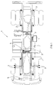
- FIG. 1 the outline of a lorry is shown, shown as a whole with reference numeral 4 and provided with a greasing system, of which are shown a grease pump 1, two metering blocks 2 and various greasing points 3.
- An alarm pressure switch is indicated with 5, and an alarm lamp positioned in the driving cab with 6, for signalling any anomalies.
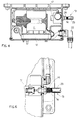
- Figure 2 shows a partial enlarged view of a part of the pump 1 and a metering block 2.
- the pump 1 comprises a grease tank 15 and a pumping unit with pistons 16 located below the tank 15.
- a metallic plate 18 is positioned, bordered with a double lipped sealing gasket 19, constantly pressed downwards by a pressure spring 20, acting between such plate and the upper part of the tank 25 in such a way as to exert pressure on the grease.
- the plate 18 and the related spring 20 are shown in the condition where the tank is full (A) and in the condition where the tank is empty (B), in the right half and the left half respectively of the figure.
- a timer 12 (figures 2 and 4) is programmed on the basis of the needs of the lorry, for the purpose of ;
- heating of the grease is foreseen in the pump 1 by means of an electrical resistance 22 mounted around the grease inlet well in the motor piston.
- thermostat is shown with 27 for operating the resistance 25 and under lock and key in the cab of the vehicle.
- heating of the grease in circulation can also be foreseen, particularly in the run which goes from the pump 1 to the metering units 2, through the pipes 13, only one of which is shown in figure 2.
- the grease feeder pipes 13 usually comprise an inner pipe made of polyamide, surrounded by a steel plait 14 (figure 6) and covered with a polyurethane sheath 23, it is sufficient to apply metal clamps 24 to the two ends respectively of the pipe 13, in contact with the metallic plait 14 and pass a current along the plait 14, connecting it to the battery 7, as shown in figure 2.
Landscapes
- Engineering & Computer Science (AREA)
- General Engineering & Computer Science (AREA)
- Mechanical Engineering (AREA)
- Fluid-Pressure Circuits (AREA)
- Component Parts Of Construction Machinery (AREA)
Applications Claiming Priority (2)
| Application Number | Priority Date | Filing Date | Title |
|---|---|---|---|
| ITMI922477A IT1255936B (it) | 1992-10-29 | 1992-10-29 | Impianto di ingrassaggio automatico |
| ITMI922477 | 1992-10-29 |
Publications (1)
| Publication Number | Publication Date |
|---|---|
| EP0595097A1 true EP0595097A1 (de) | 1994-05-04 |
Family
ID=11364191
Family Applications (1)
| Application Number | Title | Priority Date | Filing Date |
|---|---|---|---|
| EP93116418A Withdrawn EP0595097A1 (de) | 1992-10-29 | 1993-10-11 | Automatisches Schmiersystem |
Country Status (2)
| Country | Link |
|---|---|
| EP (1) | EP0595097A1 (de) |
| IT (1) | IT1255936B (de) |
Cited By (9)
| Publication number | Priority date | Publication date | Assignee | Title |
|---|---|---|---|---|
| EP1209038A1 (de) * | 2000-11-10 | 2002-05-29 | Baier & Köppel GmbH & Co. KG | Fahrzeuggebundene Zentralschmieranlage |
| JP2012132437A (ja) * | 2010-12-20 | 2012-07-12 | Lincoln Gmbh | 潤滑剤ポンプ、およびポンプヒータを有する潤滑システム |
| WO2013068037A1 (en) | 2011-11-08 | 2013-05-16 | Aktiebolaget Skf | Lubrication system |
| DE102008043143C5 (de) * | 2008-10-23 | 2014-12-31 | Jost-Werke Gmbh | Schmieranlage mit integrierter Elektronik |
| CN105135189A (zh) * | 2015-06-05 | 2015-12-09 | 黄勤 | 干油润滑站 |
| EP1846281B2 (de) † | 2005-02-11 | 2016-06-22 | Jost-Werke GmbH | Schmiersystem für eine sattelkupplung eines zugfahrzeuges |
| CN107300119A (zh) * | 2017-07-21 | 2017-10-27 | 南方中金环境股份有限公司 | 一种带有加热装置的电动润滑油脂泵 |
| CN110644132A (zh) * | 2019-10-17 | 2020-01-03 | 美名格-艾罗(太仓)纺织机械有限公司 | 智能喷雾式加油机控制调节系统 |
| US12215823B2 (en) | 2019-06-26 | 2025-02-04 | Graco Minnesota Inc. | Heated lubricant pump |
Citations (4)
| Publication number | Priority date | Publication date | Assignee | Title |
|---|---|---|---|---|
| DE67382C (de) * | J. F. A. HÖPER in Hamburg, Gr. Reichenstr. 3/5, und A. JACOBSEN in Hamburg, Neuerwall 26 pt | Fettschmiervorrichtung mit Erwärmung des Fettes durch elektrischen Strom | ||
| GB570353A (en) * | 1943-12-06 | 1945-07-03 | Tecalemit Ltd | Improvements in lubricating systems |
| US3985205A (en) * | 1975-01-08 | 1976-10-12 | Ab Assa | Lubricating system |
| DE2536661A1 (de) * | 1975-08-16 | 1977-02-24 | Skf Kugellagerfabriken Gmbh | Einrichtung zum dosierten abgeben von stoffen |
-
1992
- 1992-10-29 IT ITMI922477A patent/IT1255936B/it active IP Right Grant
-
1993
- 1993-10-11 EP EP93116418A patent/EP0595097A1/de not_active Withdrawn
Patent Citations (4)
| Publication number | Priority date | Publication date | Assignee | Title |
|---|---|---|---|---|
| DE67382C (de) * | J. F. A. HÖPER in Hamburg, Gr. Reichenstr. 3/5, und A. JACOBSEN in Hamburg, Neuerwall 26 pt | Fettschmiervorrichtung mit Erwärmung des Fettes durch elektrischen Strom | ||
| GB570353A (en) * | 1943-12-06 | 1945-07-03 | Tecalemit Ltd | Improvements in lubricating systems |
| US3985205A (en) * | 1975-01-08 | 1976-10-12 | Ab Assa | Lubricating system |
| DE2536661A1 (de) * | 1975-08-16 | 1977-02-24 | Skf Kugellagerfabriken Gmbh | Einrichtung zum dosierten abgeben von stoffen |
Cited By (11)
| Publication number | Priority date | Publication date | Assignee | Title |
|---|---|---|---|---|
| EP1209038A1 (de) * | 2000-11-10 | 2002-05-29 | Baier & Köppel GmbH & Co. KG | Fahrzeuggebundene Zentralschmieranlage |
| EP1846281B2 (de) † | 2005-02-11 | 2016-06-22 | Jost-Werke GmbH | Schmiersystem für eine sattelkupplung eines zugfahrzeuges |
| DE102008043143C5 (de) * | 2008-10-23 | 2014-12-31 | Jost-Werke Gmbh | Schmieranlage mit integrierter Elektronik |
| JP2012132437A (ja) * | 2010-12-20 | 2012-07-12 | Lincoln Gmbh | 潤滑剤ポンプ、およびポンプヒータを有する潤滑システム |
| EP2479471A3 (de) * | 2010-12-20 | 2014-10-22 | Lincoln GmbH | Schmierstoffpumpe und Schmiersystem mit Pumpenheizung |
| WO2013068037A1 (en) | 2011-11-08 | 2013-05-16 | Aktiebolaget Skf | Lubrication system |
| CN105135189A (zh) * | 2015-06-05 | 2015-12-09 | 黄勤 | 干油润滑站 |
| CN107300119A (zh) * | 2017-07-21 | 2017-10-27 | 南方中金环境股份有限公司 | 一种带有加热装置的电动润滑油脂泵 |
| US12215823B2 (en) | 2019-06-26 | 2025-02-04 | Graco Minnesota Inc. | Heated lubricant pump |
| CN110644132A (zh) * | 2019-10-17 | 2020-01-03 | 美名格-艾罗(太仓)纺织机械有限公司 | 智能喷雾式加油机控制调节系统 |
| CN110644132B (zh) * | 2019-10-17 | 2024-05-14 | 美名格-艾罗(太仓)纺织机械有限公司 | 智能喷雾式加油机控制调节系统 |
Also Published As
| Publication number | Publication date |
|---|---|
| IT1255936B (it) | 1995-11-17 |
| ITMI922477A0 (it) | 1992-10-29 |
| ITMI922477A1 (it) | 1994-04-29 |
Similar Documents
| Publication | Publication Date | Title |
|---|---|---|
| US20240318775A1 (en) | Pump having diagnostic system | |
| US4245593A (en) | Liquid heating and circulating system | |
| EP0595097A1 (de) | Automatisches Schmiersystem | |
| US9222618B2 (en) | Stepper motor driving a lubrication pump providing uninterrupted lubricant flow | |
| US5823295A (en) | Lubrication control system for a work machine | |
| US5381874A (en) | Automatic lubrication control | |
| US4249491A (en) | Multiple liquid heating and circulating system | |
| US9388940B2 (en) | Variable speed stepper motor driving a lubrication pump system | |
| EP2713091A2 (de) | Drehzahlvariabler Schrittmotor zum Antreiben eines Schmierölpumpsystems | |
| US20080142304A1 (en) | System and method for lubricating a transportation system | |
| EP1353075A3 (de) | Ansteuereinrichtung für mindestens einen Verbraucher, wie Nockenwellenversteller, automatisches Getriebe und dergleichen, von Fahrzeugen, vorzugsweise Kraftfahrzeugen | |
| WO2015020644A1 (en) | Lubrication system and controller | |
| DE3904952C1 (de) | ||
| DE10204245B4 (de) | Einrichtung zum Versorgen von mehreren Versorgungsstellen, wie Schmierstellen | |
| US4738600A (en) | Lubricating system | |
| EP0794323B1 (de) | Ölnachfüllautomatik | |
| US6397811B1 (en) | Electronically controlled lubricating oil removal system | |
| DE102011118836B4 (de) | Doppelpumpenaggregat mit gegenläufigen Förderrichtungen und Verfahren zum Betrieb desselben | |
| GB2215410A (en) | Lubricating device | |
| EP0086602A1 (de) | Vorrichtung zur Temperaturregelung von Brennstoff für die Versorgung eines Fahrzeugmotors oder ähnlichem | |
| DE1600352A1 (de) | Einrichtung zum Nachfuellen von Schmieroel in die OElwanne einer Kraftmaschine | |
| US4186654A (en) | Recirculating lubrication system | |
| DE3902138A1 (de) | Hydrostatischer antrieb von nebenaggregaten eines kraftfahrzeugs | |
| DE102016218835B4 (de) | Ölversorgungseinheit und Kraftfahrzeug | |
| CA1087473A (en) | Liquid heating and circulating system |
Legal Events
| Date | Code | Title | Description |
|---|---|---|---|
| PUAI | Public reference made under article 153(3) epc to a published international application that has entered the european phase |
Free format text: ORIGINAL CODE: 0009012 |
|
| AK | Designated contracting states |
Kind code of ref document: A1 Designated state(s): AT DE ES FR GB IT NL SE |
|
| 17P | Request for examination filed |
Effective date: 19940712 |
|
| 17Q | First examination report despatched |
Effective date: 19950308 |
|
| STAA | Information on the status of an ep patent application or granted ep patent |
Free format text: STATUS: THE APPLICATION IS DEEMED TO BE WITHDRAWN |
|
| 18D | Application deemed to be withdrawn |
Effective date: 19950919 |