EP0595128B1 - Vorrichtung zur lastabhängigen Regelung des Bremsdruckes an den Achsen eines Nutzfahrzeug-Doppelachsaggregates - Google Patents
Vorrichtung zur lastabhängigen Regelung des Bremsdruckes an den Achsen eines Nutzfahrzeug-Doppelachsaggregates Download PDFInfo
- Publication number
- EP0595128B1 EP0595128B1 EP93116641A EP93116641A EP0595128B1 EP 0595128 B1 EP0595128 B1 EP 0595128B1 EP 93116641 A EP93116641 A EP 93116641A EP 93116641 A EP93116641 A EP 93116641A EP 0595128 B1 EP0595128 B1 EP 0595128B1
- Authority
- EP
- European Patent Office
- Prior art keywords
- spring
- sided lever
- bolt
- lever
- resilient
- Prior art date
- Legal status (The legal status is an assumption and is not a legal conclusion. Google has not performed a legal analysis and makes no representation as to the accuracy of the status listed.)
- Expired - Lifetime
Links
- 230000001419 dependent effect Effects 0.000 title claims description 4
- 230000006835 compression Effects 0.000 claims description 25
- 238000007906 compression Methods 0.000 claims description 25
- 230000033001 locomotion Effects 0.000 claims description 6
- 230000000694 effects Effects 0.000 claims description 3
- 238000013016 damping Methods 0.000 description 2
- 230000001105 regulatory effect Effects 0.000 description 2
- 229910000639 Spring steel Inorganic materials 0.000 description 1
- 238000010276 construction Methods 0.000 description 1
- 238000003780 insertion Methods 0.000 description 1
- 230000037431 insertion Effects 0.000 description 1
- 238000012423 maintenance Methods 0.000 description 1
- 238000004519 manufacturing process Methods 0.000 description 1
Images


Classifications
-
- B—PERFORMING OPERATIONS; TRANSPORTING
- B60—VEHICLES IN GENERAL
- B60T—VEHICLE BRAKE CONTROL SYSTEMS OR PARTS THEREOF; BRAKE CONTROL SYSTEMS OR PARTS THEREOF, IN GENERAL; ARRANGEMENT OF BRAKING ELEMENTS ON VEHICLES IN GENERAL; PORTABLE DEVICES FOR PREVENTING UNWANTED MOVEMENT OF VEHICLES; VEHICLE MODIFICATIONS TO FACILITATE COOLING OF BRAKES
- B60T8/00—Arrangements for adjusting wheel-braking force to meet varying vehicular or ground-surface conditions, e.g. limiting or varying distribution of braking force
- B60T8/18—Arrangements for adjusting wheel-braking force to meet varying vehicular or ground-surface conditions, e.g. limiting or varying distribution of braking force responsive to vehicle weight or load, e.g. load distribution
- B60T8/1837—Arrangements for adjusting wheel-braking force to meet varying vehicular or ground-surface conditions, e.g. limiting or varying distribution of braking force responsive to vehicle weight or load, e.g. load distribution characterised by the load-detecting arrangements
-
- B—PERFORMING OPERATIONS; TRANSPORTING
- B60—VEHICLES IN GENERAL
- B60T—VEHICLE BRAKE CONTROL SYSTEMS OR PARTS THEREOF; BRAKE CONTROL SYSTEMS OR PARTS THEREOF, IN GENERAL; ARRANGEMENT OF BRAKING ELEMENTS ON VEHICLES IN GENERAL; PORTABLE DEVICES FOR PREVENTING UNWANTED MOVEMENT OF VEHICLES; VEHICLE MODIFICATIONS TO FACILITATE COOLING OF BRAKES
- B60T8/00—Arrangements for adjusting wheel-braking force to meet varying vehicular or ground-surface conditions, e.g. limiting or varying distribution of braking force
- B60T8/18—Arrangements for adjusting wheel-braking force to meet varying vehicular or ground-surface conditions, e.g. limiting or varying distribution of braking force responsive to vehicle weight or load, e.g. load distribution
- B60T8/1806—Arrangements for adjusting wheel-braking force to meet varying vehicular or ground-surface conditions, e.g. limiting or varying distribution of braking force responsive to vehicle weight or load, e.g. load distribution characterised by the calibration process or the means therefor
Definitions
- the invention relates to a device for the load-dependent regulation of the brake pressure at the axles of a twin axle unit of utility vehicles by means of a pressure-regulating valve which can be controlled via a master rod articulated to the two axles, a control rod articulated to said master rod, and a regulator lever articulated to said control rod, one end of said master rod being articulated to the free end of an essentially horizontal spring element extending essentially in the axial direction, the other end of said spring element being firmly connected to one of said two axles, said spring element comprising a single-sided lever and a resilient device.
- the DE-A-3 322 702 discloses a regulating device of the above-mentioned type in which a spring element is used to prevent damage to the so-called ALB regulator and the master rod.
- the spring element has to compensate for the horizontal length variation, in particular when the second axle of the twin axle unit swings. It is also necessary to compensate for the vertical overtravel when the second axle undergoes spring action in order to prevent damage to the brake pressure regulator or pressure-regulating valve and the master rod.
- the spring element comprises a damping member which is subject to a comparatively large amount of wear during operation.
- the US-A-3 410 611 discloses a load-responsive fluid-pressure control device wherein a lever is pivotally connected to a load indicating rod, in turn pivoted on a master rod linked between the two axles, and is connected by a lost motion device to a levelling device provided with damping means.
- the object of the invention is to provide a regulating device of the type initially mentioned whose spring element is a simple structure, can be operated without suffering much wear so as to prevent damage to the pressure-regulating valve and the master rod and, in particular, also compensate for the overtravel when the brake pressure regulator is fitted.
- the essence of the invention is the construction of the spring element in the form of a single-sided lever and a resilient device which acts in the vertical direction and comprises a mechanical spring.
- the first variant which is described in subclaims 3 to 5, is characterised by a resilient device with a preloaded compression spring which extends perpendicularly to the single-sided lever and through which an essentially vertical fastening bolt passes which fastens the single-sided lever to the axle.
- the fastening bolt also passes through an upper and a lower slide disc, between which discs the single-sided lever is arranged.
- the compression spring is held and restrained in spring guides at the top and bottom.
- the spring element is therefore only resilient in the vertical direction during operation. It can swing in the horizontal direction without any spring force being exerted. The force for deflecting the spring element can be adjusted. In accordance with the object, the amount of wear occurring during operation is very low. This means that the useful life of the spring element is increased.
- the second variant of the invention provides a resilient device with a preloaded mechanical compression spring which extends in the axial direction of the single-sided lever and is held in a pot which is fastened to the axle of the twin axle unit, the end of the single-sided lever which faces the compression spring comprising a fixed vertical cross-bolt, which is held and secured in the pot and vertically guided and restrained at the ends by a thrust piece, and a spherical centre of the cross-bolt pressing against a socket of the preloaded compression spring.
- the thrust piece comprises in particular vertically extending upper and lower prismatic recesses in which the free ends of the cross-bolt are guided.
- the thrust piece may alternatively comprise upper and lower semicircular recesses in which these free ends of the cross-bolt are guided.
- a retaining ring is used to secure the thrust piece in the free, unfastened end of the pot.
- the single-sided lever is in particular formed as a hollow tube with an enlargement at the end, in which enlargement the cross-bolt is fastened in the area of its ends, with the spherical centre being positioned centrally in the enlargement in a contact-free manner.
- a spring element formed in this way also permits a resilient vertical deflection of a regulator linkage, while the single-sided lever can be swung about the vertical axis of the cross-bolt when a horizontal deflection occurs without a resilient spring action taking effect.
- the result is improved control performance, i.e. the brake pressure regulator is subjected to less stress.
- the (slight) wear has no effect in functional terms.
- the individual component parts can be prefabricated as modules. They have a comparatively low weight.
- the device is comparatively unaffected by dirt during operation. Component parts can easily be replaced. Overtravel force and overtravel distances do not change when a replacement is carried out.
- the result of reducing the forces acting on the spherical head connection is particularly low-wear operation combined with an increased useful life of the device. With appropriate dimensioning, there is virtually no possibility of the pressure-regulating valve or the master rod being damaged.
- a third variant of the invention which is described in subclaims 11 to 13, is characterised by a spring element in the form of a mechanical torsion spring.
- the resilient device is therefore incorporated into the single-sided lever.
- the axis of rotation of the torsion spring extends essentially horizontally in the longitudinal direction of the vehicle, i.e. essentially perpendicularly to the vehicle axles.
- a development of the invention of this kind consists practically of a single lightweight component part which is easy to produce. Not only is there spring action in the vertical direction, but also in the horizontal direction, i.e. along the vehicle.
- the device is also subject to little wear during operation. Production costs are low and little maintenance work is required.
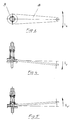
- Figure 1 is a diagrammatic plan view of a twin axle unit 3 with a first axle 1 and a second axle 2, a device being provided for the load-dependent regulation of the brake pressure at the axles 1, 2 by means of a pressure-regulating valve 4.
- the pressure-regulating valve 4 is fastened to the frame and connected to the two axles 1 and 2 via a regulator linkage.
- the latter comprises a master rod 5, which is articulated to the two axles 1 and 2, a control rod, which is articulated to the master rod, and a regulator lever which is directly or indirectly articulated to the control rod and operates the pressure-regulating valve 4 or the ALB regulator.
- the end of the master rod 5 which is at the rear of the vehicle and on the right in Figure 1 is articulated to the free end of an essentially horizontal spring element 6, which extends essentially in the axial direction.
- the non-articulated end of the spring element 6 is firmly connected to the second axle 2 of the twin axle unit, with the possibility of a spring action taking place at least in the vertical direction.
- the spring element 6 is shown in greater detail in Figures 2 and 3.
- the lower and upper vertically deflected positions of the spring element are shown in Figures 4 and 5.
- the spring element 6 comprises a single-sided lever 8 and a resilient device 9 in the form of a mechanical compression spring 10 consisting of spring steel.
- the compression spring 10 is disposed at the end of the single-sided lever 8 which is fastened to the second axle 2, the axis of the compression spring extending vertically and essentially perpendicularly to the single-sided lever 8 and being disposed at the top side of the lever.
- a vertical fastening bolt 11 is provided in particular at the fastening point and passes through the compression spring 10 and through a through-bore in the single-sided lever.
- An upper and a lower slide disc 12 are disposed in the immediate vicinity of the single-sided lever 8. Another disc, which is directly adjacent to the second axle 2 to be fastened, is disposed below the lower slide disc 12.
- the compression spring comprises an upper and a lower spring guide 13 and is preloaded downwards in the direction of the single-sided lever 8 by an upper nut 27.
- the arrangement is such that upon a vertical deflection F V of the master rod 5 a resilient deflection movement of the spring element downwards according to Figure 4 and upwards according to Figure 5 is possible.
- the single-sided lever 8 can easily be swung horizontally in the direction of the excursion s H without any resilient spring force being exerted, as shown in Figure 2. In so doing the single-sided lever 8 slides on the slide discs 12 without any appreciable frictional force.
- the entire device is arranged such that the preloading force of the vertical compression spring 10 can be adjusted by adjusting the nut 27, including the associated upper lock nut.
- the effective spring force F V can thus be adjusted. This means that it is possible to prevent damage to an ALB regulator or linkage when spring deflection takes place in the overtravel range of the ALB regulator.
- the length of the master rod between the swing axles can be compensated by the horizontal movement s H .
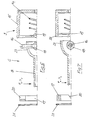
- Figures 6 and 7 are exploded views of another spring element 6 in a diagrammatic vertical section and a diagrammatic horizontal section, respectively.
- the spring element 6 comprises a single-sided tubular lever 8, whose end which is broken off on the left in the drawings is articulated to the master rod.
- the end of the single-sided lever which is on the right in the drawings comprises a tubular hemispherical enlargement 23 in which a cross-bolt 16 is fastened in the vertical direction in the area of its ends.
- the cross-bolt 16 comprises a spherical centre 18, which engages in a flexible manner in a concave holding socket 19.
- the socket 19 is supported on the other side by a compression spring 14, the other end of which is restrained against the bottom of a pot 15, which in turn is firmly connected to the second axle 2 of the twin axle unit.
- the compression spring 14 lies in an extension of the axis of the single-sided lever 8 and is preloaded by an annular thrust piece 17, which comprises a radially outer upper and lower prismatic recess 20.
- the upper and lower free ends of the cross-bolt 16 are held in the prismatic recesses 20.
- the left-hand free end of the single-sided lever 8 can be deflected by the vertical spring excursion s V according to Figure 6 upon the action of a vertical force F V when the compression spring 14 is compressed.
- a horizontal force F H is exerted the left-hand end of the single-sided lever 8 is deflected by the horizontal deflection excursion s H according to Figure 7 by swinging the single-sided lever 8 about the vertical axis of the spring bolt 16.
- the compression spring 14 is not in this case deflected or compressed and does not therefore exert any spring force.
- the single-sided lever 8 is firstly preassembled with the cross-bolt 16 and the spherical centre 18. Following the insertion of the compression spring 14, this pre-completed unit is placed in the pot 15, which is fastened to the second axle 2, after which the thrust piece is placed on the pre-completed unit such that the cross-bolt 16 comes to lie in the prismatic recesses 20, which are staggered by 180°. The entire unit is finally compressed and the retaining ring 21 mounted in the pot 15.
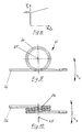
- a characteristic according to Figure 8 is achieved when the spring element 6 is positioned according to Figure 6.
- the vertical force F V is achieved by further compression of the preloaded compression spring 14 as a result of the cross-bolt 16 being supported in the upper prismatic recess 20 of the thrust piece 17 and thus moving the spherical centre 18 to the right through the vertical excursion s V and further compressing the compression spring 14.
- the prismatic recess may be replaced by a semicircular recess in the thrust piece 17 which is adapted to the outer contour of the circular cross-bolt 16.
- FIG. 9 and 10 shows a spring element 6 in which the single-sided lever 8 and the resilient mechanical spring device are integrally formed.
- the spring element 6 is in particular a torsion spring 24 with extended rectilinear paraxial ends which, according to Figure 9, are disposed at the underside of the torsion spring.
- the torsion spring 24 has an axis of rotation 25 which extends horizontally in the longitudinal direction of the vehicle.
- the end 26 shown on the left-hand side in Figures 9 and 10 is firmly secured to the second axle 2, while the master rod (not shown) is articulated to the right-hand end of the torsion spring.
- the latter end may be deflected in a resilient manner in the vertical direction over the vertical excursion s V during operation in accordance with Figure 9.
- a resilient deflection is also possible in the horizontal direction according to Figure 10 if the horizontal spring excursion s H is covered, so as to compensate for the length of the master rod when there is a swinging movement.
Landscapes
- Engineering & Computer Science (AREA)
- Transportation (AREA)
- Mechanical Engineering (AREA)
- Hydraulic Control Valves For Brake Systems (AREA)
- Braking Arrangements (AREA)
Claims (13)
- Vorrichtung zur lastabhängigen Regelung des Bremsdrucks an den Achsen (1, 2) einer Doppelachseinheit (3) von Nutzfahrzeugen mit Hilfe eines Druckregelventils (4), das mit Hilfe einer an die beiden Achsen (1, 2) angelenkten Geberstange (5), einer an diese angelenkten Steuerstange und eines an die Steuerstange angelenkten Regelhebels steuerbar ist, wobei ein Ende der Geberstange (5) an das freie Ende eines im wesentlichen in Achsrichtung verlaufenden, im wesentlichen waagerechten Federelements (6) angelenkt ist, dessen anderes Ende (7, 16, 26) fest mit einer (2) der beiden Achsen (1, 2) verbunden ist, welches Federelement (6) einen einseitigen Hebel (8) und eine elastische Einrichtung (9) umfaßt, dadurch gekennzeichnet, daß die elastische Einrichtung (9) eine mechanische Feder (10, 14, 24) aufweist, die so angeordnet ist, daß ihre Federwirkung in der senkrechten Richtung der Bewegung des einseitigen Hebels (8) wirkt, ohne die Bewegung des einseitigen Hebels (8) in waagerechter Richtung zu beeinflussen.
- Vorrichtung nach Anspruch 1, dadurch gekennzeichnet, daß die elastische Einrichtung (9) am Ende (7, 16) des einseitigen Hebels (8) vorgesehen ist, der fest mit der einen Achse (2) verbunden ist.
- Vorrichtung nach Anspruch 1 oder 2, dadurch gekennzeichnet, daß die elastische Einrichtung (9) eine vorgespannte Druckfeder (10) umfaßt, die sich im wesentlichen senkrecht erstreckt und durch die ein im wesentlichen senkrechter Befestigungsbolzen (11) hindurchgeht, der den einseitigen Hebel (8) an der Achse (2) festlegt.
- Vorrichtung nach Anspruch 3, dadurch gekennzeichnet, daß der Befestigungsbolzen (11) durch eine obere und eine untere Gleitscheibe (12) hindurchgeht, zwischen welchen Scheiben (12) der einseitige Hebel (8) angeordnet ist.
- Vorrichtung nach Anspruch 3 oder 4, dadurch gekennzeichnet, daß die Druckfeder (10) an der oberen und unteren Seite durch Federführungen (13) gehalten und abgestützt ist, durch welche Führungen (13) der Befestigungsbolzen (11) hindurchgeht.
- Vorrichtung nach Anspruch 2, dadurch gekennzeichnet, daß die elastische Einrichtung (9) eine in Achsrichtung des einseitigen Hebels (8) verlaufende, vorgespannte Druckfeder (14) umfaßt, die in einem an der Achse (2) befestigten Topf gehalten ist, und daß das Ende des einseitigen Hebels (8), das der Druckfeder (14) gegenüberliegt, einen senkrechten Querbolzen (16) aufweist, der fest mit dem Hebel verbunden ist und in dem Topf (50) befestigt ist und an den Enden durch ein Druckstück (17) geführt und verspannt ist, wobei ein Kugelzentrum (18) des Querbolzens (16) gegen eine Muffe (19) der vorgespannten Druckfeder (14) drückt.
- Vorrichtung nach Anspruch 6, dadurch gekennzeichnet, daß das Druckstück (17) vertikal verlaufende, obere und untere Prismenaussparungen (20) aufweist, in denen die freien Enden des Querbolzens (16) geführt sind.
- Vorrichtung nach Anspruch 6, dadurch gekennzeichnet, daß das Druckstück (17) senkrecht gerichtete obere und untere, halbkreisförmige Ausnehmungen aufweist, in denen die freien Enden des Querbolzens (16) geführt sind.
- Vorrichtung nach einem der Ansprüche 6 bis 8, dadurch gekennzeichnet, daß das Druckstück (17) in den freien, nicht befestigten Enden (22) des Topfes (15) durch einen Haltering (21) gesichert ist.
- Vorrichtung nach einem der Ansprüche 6 bis 9, dadurch gekennzeichnet, daß der einseitige Hebel (8) ein hohles Rohr mit einer Erweiterung (23) am Ende ist, in welcher Erweiterung der Querbolzen (16) im Bereich seiner Enden befestigt ist, wobei das Kugelzentrum (18) zentral in der Erweiterung (23) in kontaktfreier Weise angeordnet ist.
- Vorrichtung nach Anspruch 1, dadurch gekennzeichnet, daß die elastische Einrichtung (9) in den einseitigen Hebel (8) integriert und als Torsionsfeder (24) ausgebildet ist.
- Vorrichtung nach Anspruch 11, dadurch gekennzeichnet, daß die Drehachse (25) der Torsionsfeder (24) im wesentlichen waagerecht in der Längsrichtung des Fahrzeugs verlauft.
- Vorrichtung nach Anspruch 11 oder 12, dadurch gekennzeichnet, daß das eine Ende (26) der Torsionsfeder (24) fest mit der Achse (2) verbunden ist, während das andere Ende der Torsionsfeder (24) gelenkig mit der Geberstange (5) verbunden ist.
Applications Claiming Priority (2)
| Application Number | Priority Date | Filing Date | Title |
|---|---|---|---|
| DE4236241A DE4236241A1 (de) | 1992-10-27 | 1992-10-27 | Vorrichtung zur lastabhängigen Regelung des Bremsdruckes an den Achsen eines Nutzfahrzeug-Doppelachsaggregates |
| DE4236241 | 1992-10-27 |
Publications (2)
| Publication Number | Publication Date |
|---|---|
| EP0595128A1 EP0595128A1 (de) | 1994-05-04 |
| EP0595128B1 true EP0595128B1 (de) | 1997-01-08 |
Family
ID=6471463
Family Applications (1)
| Application Number | Title | Priority Date | Filing Date |
|---|---|---|---|
| EP93116641A Expired - Lifetime EP0595128B1 (de) | 1992-10-27 | 1993-10-14 | Vorrichtung zur lastabhängigen Regelung des Bremsdruckes an den Achsen eines Nutzfahrzeug-Doppelachsaggregates |
Country Status (3)
| Country | Link |
|---|---|
| EP (1) | EP0595128B1 (de) |
| DE (2) | DE4236241A1 (de) |
| ES (1) | ES2097420T3 (de) |
Families Citing this family (1)
| Publication number | Priority date | Publication date | Assignee | Title |
|---|---|---|---|---|
| CH695492A5 (de) | 2001-08-29 | 2006-06-15 | Carosserie Baldinger Ag | Bremskraftregeleinrichtung an einem Fahrzeug. |
Family Cites Families (5)
| Publication number | Priority date | Publication date | Assignee | Title |
|---|---|---|---|---|
| CH319820A (de) * | 1953-03-18 | 1957-02-28 | Westinghouse Bremsen Ges Mbh | Einrichtung zur lastabhängigen Einstellung des Steuerventils von Anhänger-Druckluftbremsen |
| DE1183814B (de) * | 1961-12-15 | 1964-12-17 | Luther Werke Luther G M B H & | Ausgleichgestaenge fuer Doppelachsaggregate zur Steuerung automatisch lastabhaengiger Bremskraftregler |
| GB1172101A (en) * | 1966-04-07 | 1969-11-26 | Girling Ltd | Improvements in or relating to Hydraulic Brake Control Valves |
| US3410611A (en) * | 1966-12-29 | 1968-11-12 | Pullman Inc | Load-responsive fluid-pressure control means |
| DE3322702A1 (de) * | 1981-12-24 | 1985-01-10 | Iveco Magirus AG, 7900 Ulm | Vorrichtung zur lastabhaengigen regelung des bremsdruckes an den achsen eines doppelachsaggregates eines fahrzeuges |
-
1992
- 1992-10-27 DE DE4236241A patent/DE4236241A1/de not_active Withdrawn
-
1993
- 1993-10-14 ES ES93116641T patent/ES2097420T3/es not_active Expired - Lifetime
- 1993-10-14 EP EP93116641A patent/EP0595128B1/de not_active Expired - Lifetime
- 1993-10-14 DE DE69307260T patent/DE69307260T2/de not_active Expired - Fee Related
Also Published As
| Publication number | Publication date |
|---|---|
| DE4236241A1 (de) | 1994-04-28 |
| EP0595128A1 (de) | 1994-05-04 |
| DE69307260D1 (de) | 1997-02-20 |
| DE69307260T2 (de) | 1997-07-17 |
| ES2097420T3 (es) | 1997-04-01 |
Similar Documents
| Publication | Publication Date | Title |
|---|---|---|
| US4650027A (en) | Coupling device between a front suspension and a rear suspension of a vehicle | |
| US5046752A (en) | Axle suspension system | |
| US6206407B1 (en) | Vehicle suspension system | |
| CA1231123A (en) | Snowmobile ski suspension | |
| US20080258361A1 (en) | Suspension spring mount | |
| CA1316550C (en) | Suspension brake torque reaction leaf | |
| US5505521A (en) | Sprung seat frame | |
| US4438970A (en) | Vehicle cab suspension | |
| US4497507A (en) | Vehicle axle suspension | |
| US5356162A (en) | Retractable running gear for a vehicle that is supported without contact | |
| US6220580B1 (en) | Leaf spring pivot bearing and assembly with adjustment pilot | |
| US6726229B2 (en) | Integral spring damper and cross member | |
| AU2008264208A1 (en) | Bogie | |
| US5251886A (en) | Semi-elliptical spring suspension with automatic spring rate varying capacity | |
| US6273002B1 (en) | Rail vehicle with a vertical support actuator | |
| GB2123764A (en) | Motorcycle suspension | |
| US6131520A (en) | Rail vehicle | |
| EP0217799A1 (de) | Aufhängung für fahrzeug | |
| US4589675A (en) | Active suspension system | |
| US7503553B2 (en) | Utility vehicle mounting assembly | |
| EP0058950A2 (de) | Unabhängige Radaufhängungsvorrichtung für Kraftfahrzeuge | |
| CA1219171A (en) | Single axle suspension system for railroad vehicle | |
| EP0595128A1 (de) | Vorrichtung zur lastabhängigen Regelung des Bremsdruckes an den Achsen eines Nutzfahrzeug-Doppelachsaggregates | |
| US4277085A (en) | Transport vehicle | |
| EP0413318A1 (de) | Achsaufhängungssystem |
Legal Events
| Date | Code | Title | Description |
|---|---|---|---|
| PUAI | Public reference made under article 153(3) epc to a published international application that has entered the european phase |
Free format text: ORIGINAL CODE: 0009012 |
|
| AK | Designated contracting states |
Kind code of ref document: A1 Designated state(s): DE ES FR GB IT NL SE |
|
| 17P | Request for examination filed |
Effective date: 19941025 |
|
| 17Q | First examination report despatched |
Effective date: 19950515 |
|
| GRAG | Despatch of communication of intention to grant |
Free format text: ORIGINAL CODE: EPIDOS AGRA |
|
| GRAH | Despatch of communication of intention to grant a patent |
Free format text: ORIGINAL CODE: EPIDOS IGRA |
|
| GRAH | Despatch of communication of intention to grant a patent |
Free format text: ORIGINAL CODE: EPIDOS IGRA |
|
| GRAA | (expected) grant |
Free format text: ORIGINAL CODE: 0009210 |
|
| AK | Designated contracting states |
Kind code of ref document: B1 Designated state(s): DE ES FR GB IT NL SE |
|
| REF | Corresponds to: |
Ref document number: 69307260 Country of ref document: DE Date of ref document: 19970220 |
|
| ITF | It: translation for a ep patent filed | ||
| ET | Fr: translation filed | ||
| REG | Reference to a national code |
Ref country code: ES Ref legal event code: FG2A Ref document number: 2097420 Country of ref document: ES Kind code of ref document: T3 |
|
| PLBE | No opposition filed within time limit |
Free format text: ORIGINAL CODE: 0009261 |
|
| STAA | Information on the status of an ep patent application or granted ep patent |
Free format text: STATUS: NO OPPOSITION FILED WITHIN TIME LIMIT |
|
| 26N | No opposition filed | ||
| REG | Reference to a national code |
Ref country code: GB Ref legal event code: IF02 |
|
| PGFP | Annual fee paid to national office [announced via postgrant information from national office to epo] |
Ref country code: GB Payment date: 20031016 Year of fee payment: 11 Ref country code: FR Payment date: 20031016 Year of fee payment: 11 |
|
| PGFP | Annual fee paid to national office [announced via postgrant information from national office to epo] |
Ref country code: NL Payment date: 20031021 Year of fee payment: 11 |
|
| PGFP | Annual fee paid to national office [announced via postgrant information from national office to epo] |
Ref country code: SE Payment date: 20031022 Year of fee payment: 11 |
|
| PGFP | Annual fee paid to national office [announced via postgrant information from national office to epo] |
Ref country code: ES Payment date: 20031030 Year of fee payment: 11 |
|
| PGFP | Annual fee paid to national office [announced via postgrant information from national office to epo] |
Ref country code: DE Payment date: 20031127 Year of fee payment: 11 |
|
| PG25 | Lapsed in a contracting state [announced via postgrant information from national office to epo] |
Ref country code: GB Free format text: LAPSE BECAUSE OF NON-PAYMENT OF DUE FEES Effective date: 20041014 |
|
| PG25 | Lapsed in a contracting state [announced via postgrant information from national office to epo] |
Ref country code: SE Free format text: LAPSE BECAUSE OF NON-PAYMENT OF DUE FEES Effective date: 20041015 Ref country code: ES Free format text: LAPSE BECAUSE OF NON-PAYMENT OF DUE FEES Effective date: 20041015 |
|
| PG25 | Lapsed in a contracting state [announced via postgrant information from national office to epo] |
Ref country code: NL Free format text: LAPSE BECAUSE OF NON-PAYMENT OF DUE FEES Effective date: 20050501 |
|
| PG25 | Lapsed in a contracting state [announced via postgrant information from national office to epo] |
Ref country code: DE Free format text: LAPSE BECAUSE OF NON-PAYMENT OF DUE FEES Effective date: 20050503 |
|
| EUG | Se: european patent has lapsed | ||
| GBPC | Gb: european patent ceased through non-payment of renewal fee |
Effective date: 20041014 |
|
| PG25 | Lapsed in a contracting state [announced via postgrant information from national office to epo] |
Ref country code: FR Free format text: LAPSE BECAUSE OF NON-PAYMENT OF DUE FEES Effective date: 20050630 |
|
| NLV4 | Nl: lapsed or anulled due to non-payment of the annual fee |
Effective date: 20050501 |
|
| REG | Reference to a national code |
Ref country code: FR Ref legal event code: ST |
|
| PG25 | Lapsed in a contracting state [announced via postgrant information from national office to epo] |
Ref country code: IT Free format text: LAPSE BECAUSE OF NON-PAYMENT OF DUE FEES;WARNING: LAPSES OF ITALIAN PATENTS WITH EFFECTIVE DATE BEFORE 2007 MAY HAVE OCCURRED AT ANY TIME BEFORE 2007. THE CORRECT EFFECTIVE DATE MAY BE DIFFERENT FROM THE ONE RECORDED. Effective date: 20051014 |
|
| REG | Reference to a national code |
Ref country code: ES Ref legal event code: FD2A Effective date: 20041015 |