EP0595191A1 - Spannungsregler für einen elektrischen Generator, speziell für einen Alternator - Google Patents
Spannungsregler für einen elektrischen Generator, speziell für einen Alternator Download PDFInfo
- Publication number
- EP0595191A1 EP0595191A1 EP93117028A EP93117028A EP0595191A1 EP 0595191 A1 EP0595191 A1 EP 0595191A1 EP 93117028 A EP93117028 A EP 93117028A EP 93117028 A EP93117028 A EP 93117028A EP 0595191 A1 EP0595191 A1 EP 0595191A1
- Authority
- EP
- European Patent Office
- Prior art keywords
- voltage
- regulator according
- capacitor
- switching means
- vbatt
- Prior art date
- Legal status (The legal status is an assumption and is not a legal conclusion. Google has not performed a legal analysis and makes no representation as to the accuracy of the status listed.)
- Withdrawn
Links
Images
Classifications
-
- H—ELECTRICITY
- H02—GENERATION; CONVERSION OR DISTRIBUTION OF ELECTRIC POWER
- H02J—ELECTRIC POWER NETWORKS; CIRCUIT ARRANGEMENTS OR SYSTEMS FOR SUPPLYING OR DISTRIBUTING ELECTRIC POWER; SYSTEMS FOR STORING ELECTRIC ENERGY
- H02J7/00—Circuit arrangements for charging or discharging batteries or for supplying loads from batteries
- H02J7/14—Circuit arrangements for charging or discharging batteries or for supplying loads from batteries for charging batteries from dynamo-electric generators driven at varying speed, e.g. on vehicle
- H02J7/1469—Regulation of the charging current or voltage otherwise than by variation of field
- H02J7/1492—Regulation of the charging current or voltage otherwise than by variation of field by means of controlling devices between the generator output and the battery
-
- Y—GENERAL TAGGING OF NEW TECHNOLOGICAL DEVELOPMENTS; GENERAL TAGGING OF CROSS-SECTIONAL TECHNOLOGIES SPANNING OVER SEVERAL SECTIONS OF THE IPC; TECHNICAL SUBJECTS COVERED BY FORMER USPC CROSS-REFERENCE ART COLLECTIONS [XRACs] AND DIGESTS
- Y02—TECHNOLOGIES OR APPLICATIONS FOR MITIGATION OR ADAPTATION AGAINST CLIMATE CHANGE
- Y02T—CLIMATE CHANGE MITIGATION TECHNOLOGIES RELATED TO TRANSPORTATION
- Y02T10/00—Road transport of goods or passengers
- Y02T10/80—Technologies aiming to reduce greenhouse gasses emissions common to all road transportation technologies
- Y02T10/92—Energy efficient charging or discharging systems for batteries, ultracapacitors, supercapacitors or double-layer capacitors specially adapted for vehicles
Definitions
- the present invention relates to a voltage regulator usable in particular in association with an electrical generator in a vehicle having an internal combustion engine.
- an electrical generator for vehicles is constituted by a synchronous, rotary electrical machine, normally an alternator, and by a multiphase rectifier bridge for outputting a direct electrical current.
- the voltage-regulator circuits use conventional semiconductor circuits or switching regulator circuits such as, for example, that described in the present Applicant's European patent appln. No. 90830291.2 filed on 26th June 1990.
- This application describes a voltage-regulator circuit which uses a switching regulator with a working frequency of about 40 kHz, regulated by pulse-amplitude modulation.
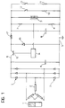
- Figure 1 shows an alternator constituted by a permanent-magnet inductor 1 and an armature constituted by windings 2.
- the windings 2 are connected to a three-phase rectifier bridge of which the rectifier elements, indicated 3, are diodes.
- a capacitor 4 connected to the output of the rectifier bridge between the positive terminal 6 and the negative terminal 5 which, typically, is connected to the earth of the vehicle, has the purpose of smoothing the waveform of the voltage output by the rectifier bridge.
- the voltage across the capacitor 4 which is the voltage output from the rectifier bridge, depends on the rate of rotation of the alternator which in turn depends on the rate of rotation of the internal combustion engine of the vehicle. Clearly, therefore, the voltage across the capacitor 4 is variable according to the rate of rotation of the engine and, in many cases, is too high to be applied to the battery 9 of the vehicle. It is therefore necessary to interpose between the rectifier bridge and the battery 9 a voltage regulator, the function of which is to reduce the voltage to a value suitable for the battery 9.
- the voltage regulator is constituted by a switching circuit in a configuration known as a step-down configuration.
- a switch typically a MOS transistor, with controlled switching, that is, into the cut-off condition or into the fully-conductive (saturated) condition, is connected to the positive pole 6 of the rectifier bridge.
- a coil 17 is connected to the output of the transistor 15 and is connected in turn to the positive terminal of the battery 9.
- the cathode of a rectifier diode 16 is also connected to the output of the transistor 15 and its anode is connected to earth.
- the current supplied also charges a capacitor 18 connected in parallel with the battery 9. At this stage, the current flowing stores energy in the coil 17.
- the capacitor 18 maintains the voltage to the battery 9 and the loads 10 and 11 whilst the energy stored in the coil 17 causes current to be recycled from earth 5 through the diode 16.
- the transistor 15 is controlled so as to be cut off or made fully conductive (saturated) by a control circuit 14 operating with pulse-amplitude modulation.
- the control circuit 14 achieves the regulation by detecting the voltage across the capacitor 18 by means of a connection to the intermediate junction of a voltage divider which is constituted by resistances 7 and 8 and is connected in parallel with the capacitor 18 and the battery 9.
- the value detected at the intermediate junction of the voltage divider 7, 8 is compared with a reference voltage generated within the control circuit 14.
- the switching frequency of the transistor reaches values of about 40 kHz.
- the regulator circuit described above has some technical disadvantages.
- a first disadvantage is due to the radio-frequency electromagnetic emissions caused by the high frequency at which the transistor 15 is switched (40 kHz).
- a second disadvantage is due to the complexity of the circuit and to its cost and bulk.
- the object of the present invention is to provide a voltage regulator which solves all the problems mentioned above in a satisfactory manner and, in particular, which provides a simpler and less bulky regulator which is completely free of radio-frequency electromagnetic emissions.
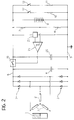
- a capacitor 4 is connected to the output of the rectifier bridge, between the positive terminal 6 and the earth terminal 5.
- the capacitor 4 has a capacitance of several hundreds of microfarads and its function is mainly to limit the voltage peaks which occur during the opening of a controlled switch 19 interposed between the positive terminal 6 and the battery 9.
- the opening and closing of the switch 19 are controlled by a control circuit 21 which is essentially a voltage comparator.
- the voltage comparator 21 compares a reference voltage generated in known manner by a reference-voltage generator 22 with a voltage detected at the intermediate junction of a voltage divider which is constituted by the resistances 7 and 8 and is disposed in parallel with the battery 9. In practice, the comparator 21 compares the voltage across the battery 9 with the reference value Vref.
- the output of the threshold comparator 21 is brought to a condition such that the switch element 19 is made fully conductive.
- the current can thus flow from the positive terminal 6 towards the battery 9, the loads 10, 11 (if they are connected by means of the switches 12, 13), and the capacitor 20 connected in parallel with the battery 9.
- the current supplied by the alternator charges the capacitor 20 and the voltage across the battery 9 and the loads 10, 11 starts to increase.
- the switch 19 remains conductive until the voltage across the battery 9 has risen to a predetermined maximum value V2 > Vref, at which value the output of the threshold comparator 21 ceases to keep the switch 19 conductive, causing it to open.
- the capacitor 20 is then discharged into the loads 10, 11 and the voltage across the battery 9 falls until it reaches V1 ⁇ Vref; at this point, the cycle bust described starts again.
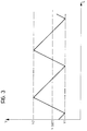
- the regulator thus operates by keeping the voltage across the users 10, 11 and the battery 9 between the minimum and maximum values V1 and V2 which are close to the nominal voltage Vbatt of the battery.
- Figure 3 shows, purely by way of indication, the curve of the voltage across the loads 10, 11, the battery 9 and the capacitor 20.
- the capacitor 20 is preferably formed with the use of supercapacitor technology: for example, a capacitor with a capacitance of 2 farads and an internal resistance of less than 100 milliohms is used. With such a capacitor and with an absorbtion of 100 amperes by the loads, a switching frequency of the switch 19 of the order of tens of Hz is obtained.
- a conventional mechanical switch or a static switch formed by semiconductor technology may thus be used equally well for the switch 19.
- the voltage regulator according to the present invention is simple and compact and has the considerable advantage that it is free of radio-frequency emissions.
Landscapes
- Engineering & Computer Science (AREA)
- Power Engineering (AREA)
- Control Of Eletrric Generators (AREA)
Applications Claiming Priority (2)
| Application Number | Priority Date | Filing Date | Title |
|---|---|---|---|
| ITTO920876 | 1992-10-28 | ||
| ITTO920876A IT1257173B (it) | 1992-10-28 | 1992-10-28 | Dispositivo per la regolazione della tensione per un generatore elettrico, in particolare un alternatore. |
Publications (1)
| Publication Number | Publication Date |
|---|---|
| EP0595191A1 true EP0595191A1 (de) | 1994-05-04 |
Family
ID=11410816
Family Applications (1)
| Application Number | Title | Priority Date | Filing Date |
|---|---|---|---|
| EP93117028A Withdrawn EP0595191A1 (de) | 1992-10-28 | 1993-10-21 | Spannungsregler für einen elektrischen Generator, speziell für einen Alternator |
Country Status (2)
| Country | Link |
|---|---|
| EP (1) | EP0595191A1 (de) |
| IT (1) | IT1257173B (de) |
Cited By (18)
| Publication number | Priority date | Publication date | Assignee | Title |
|---|---|---|---|---|
| DE19519298A1 (de) * | 1995-05-26 | 1996-11-28 | Bosch Gmbh Robert | Vorrichtung zur Spannungsversorgung mit zwei Ausgangsspannungen |
| WO2000031859A1 (en) * | 1998-11-23 | 2000-06-02 | Jung Hun Lee | Small portable flat generator |
| WO2004047262A3 (en) * | 2002-11-15 | 2004-08-26 | Sprint Communications Co | Rectifier-super capacitor device for use in a power system for a telecommunication facility |
| US6885112B2 (en) | 2002-11-15 | 2005-04-26 | Sprint Communications Company L.P. | Proton exchange membrane based power system for a telecommunication facility |
| US6930402B1 (en) | 2003-05-15 | 2005-08-16 | Sprint Communications Company L.P. | Power system for a telecommunication facility |
| US7081687B2 (en) | 2004-07-22 | 2006-07-25 | Sprint Communications Company L.P. | Power system for a telecommunications facility |
| US7245032B2 (en) | 2002-11-15 | 2007-07-17 | Sprint Communications Company L.P. | Mobile-power system utilizing propane generator, fuel cell and super capacitors |
| FR2899735A1 (fr) * | 2006-04-11 | 2007-10-12 | Peugeot Citroen Automobiles Sa | Dispositif et procede de charge d'une batterie, vehicule equipe de ce dispositif |
| US7370666B2 (en) | 2005-09-14 | 2008-05-13 | Sprint Communications Company L.P. | Power system with computer-controlled fuel system |
| US7456513B2 (en) | 2002-11-15 | 2008-11-25 | Sprint Communications Company L.P. | Modular cell site with air-turbine backup |
| US7557531B2 (en) | 2005-12-19 | 2009-07-07 | Sprint Communications Company L.P. | Power system utilizing flow batteries |
| US7602073B2 (en) | 2002-11-15 | 2009-10-13 | Sprint Communications Company L.P. | Power system with fuel cell and localized air-conditioning for computing equipment |
| US7615889B2 (en) | 2005-05-02 | 2009-11-10 | Sprint Communications Company L.P. | Modular cell site |
| US7629707B2 (en) | 2005-06-15 | 2009-12-08 | Sprint Communications Company L.P. | Power system with hydrogen on demand |
| US7629708B1 (en) | 2007-10-19 | 2009-12-08 | Sprint Communications Company L.P. | Redundant power system having a photovoltaic array |
| US7728458B2 (en) | 2006-01-05 | 2010-06-01 | Sprint Communications Company L.P. | Telecommunications megasite with backup power system |
| US9627729B2 (en) | 2005-05-18 | 2017-04-18 | Sprint Communications Company L.P. | Power system for a telecommunications network |
| EP3361600B1 (de) * | 2013-08-15 | 2022-01-26 | Fontem Holdings 4 B.V. | Verfahren, system und vorrichtung für schalterlose detektion und aufladung |
Citations (5)
| Publication number | Priority date | Publication date | Assignee | Title |
|---|---|---|---|---|
| CH403026A (de) * | 1962-08-08 | 1965-11-30 | Bosch Gmbh Robert | Einrichtung mit einer mit stark wechselnden Drehzahlen antreibbaren Wechsel- oder Drehstromlichtmaschine |
| GB2015212A (en) * | 1978-01-24 | 1979-09-05 | Nada Electronics Ltd | Voltage regulation |
| FR2533375A1 (fr) * | 1982-09-22 | 1984-03-23 | Renault | Dispositif generateur d'energie electrique pour vehicule, a alternateur polyphase et regulateur de tension |
| WO1992012563A1 (en) * | 1990-12-31 | 1992-07-23 | Motorola, Inc. | Integral battery charging and supply regulation circuit |
| US5153497A (en) * | 1991-08-28 | 1992-10-06 | Eiden Glenn E | Circuit for regulating charging of a storage battery by a photovoltaic array |
-
1992
- 1992-10-28 IT ITTO920876A patent/IT1257173B/it active IP Right Grant
-
1993
- 1993-10-21 EP EP93117028A patent/EP0595191A1/de not_active Withdrawn
Patent Citations (5)
| Publication number | Priority date | Publication date | Assignee | Title |
|---|---|---|---|---|
| CH403026A (de) * | 1962-08-08 | 1965-11-30 | Bosch Gmbh Robert | Einrichtung mit einer mit stark wechselnden Drehzahlen antreibbaren Wechsel- oder Drehstromlichtmaschine |
| GB2015212A (en) * | 1978-01-24 | 1979-09-05 | Nada Electronics Ltd | Voltage regulation |
| FR2533375A1 (fr) * | 1982-09-22 | 1984-03-23 | Renault | Dispositif generateur d'energie electrique pour vehicule, a alternateur polyphase et regulateur de tension |
| WO1992012563A1 (en) * | 1990-12-31 | 1992-07-23 | Motorola, Inc. | Integral battery charging and supply regulation circuit |
| US5153497A (en) * | 1991-08-28 | 1992-10-06 | Eiden Glenn E | Circuit for regulating charging of a storage battery by a photovoltaic array |
Cited By (25)
| Publication number | Priority date | Publication date | Assignee | Title |
|---|---|---|---|---|
| DE19519298A1 (de) * | 1995-05-26 | 1996-11-28 | Bosch Gmbh Robert | Vorrichtung zur Spannungsversorgung mit zwei Ausgangsspannungen |
| WO2000031859A1 (en) * | 1998-11-23 | 2000-06-02 | Jung Hun Lee | Small portable flat generator |
| WO2004047262A3 (en) * | 2002-11-15 | 2004-08-26 | Sprint Communications Co | Rectifier-super capacitor device for use in a power system for a telecommunication facility |
| US6885112B2 (en) | 2002-11-15 | 2005-04-26 | Sprint Communications Company L.P. | Proton exchange membrane based power system for a telecommunication facility |
| US8106533B1 (en) | 2002-11-15 | 2012-01-31 | Sprint Communications Company L.P. | Power system |
| US7875995B2 (en) | 2002-11-15 | 2011-01-25 | Sprint Communications Company L.P. | Power system for a device |
| US7098548B2 (en) | 2002-11-15 | 2006-08-29 | Sprint Communications Company L.P. | Power system for a telecommunication facility |
| US7602073B2 (en) | 2002-11-15 | 2009-10-13 | Sprint Communications Company L.P. | Power system with fuel cell and localized air-conditioning for computing equipment |
| US7157803B2 (en) | 2002-11-15 | 2007-01-02 | Sprint Communications Company L.P. | Power system including lithium-metal-polymer batteries |
| US7456513B2 (en) | 2002-11-15 | 2008-11-25 | Sprint Communications Company L.P. | Modular cell site with air-turbine backup |
| US7245032B2 (en) | 2002-11-15 | 2007-07-17 | Sprint Communications Company L.P. | Mobile-power system utilizing propane generator, fuel cell and super capacitors |
| US7298053B2 (en) | 2003-05-15 | 2007-11-20 | Sprint Communications Company L.P. | Power system for a telecommunication facility |
| US6930402B1 (en) | 2003-05-15 | 2005-08-16 | Sprint Communications Company L.P. | Power system for a telecommunication facility |
| US7112891B2 (en) | 2003-05-15 | 2006-09-26 | Sprint Communications Company L.P. | Mobile-power system with solar-powered hydrogen liberator, fuel cell, turbine, and capacitors |
| US7081687B2 (en) | 2004-07-22 | 2006-07-25 | Sprint Communications Company L.P. | Power system for a telecommunications facility |
| US7245034B2 (en) | 2004-07-22 | 2007-07-17 | Sprint Communications Company L.P. | Power system for a telecommunications facility |
| US7615889B2 (en) | 2005-05-02 | 2009-11-10 | Sprint Communications Company L.P. | Modular cell site |
| US9627729B2 (en) | 2005-05-18 | 2017-04-18 | Sprint Communications Company L.P. | Power system for a telecommunications network |
| US7629707B2 (en) | 2005-06-15 | 2009-12-08 | Sprint Communications Company L.P. | Power system with hydrogen on demand |
| US7370666B2 (en) | 2005-09-14 | 2008-05-13 | Sprint Communications Company L.P. | Power system with computer-controlled fuel system |
| US7557531B2 (en) | 2005-12-19 | 2009-07-07 | Sprint Communications Company L.P. | Power system utilizing flow batteries |
| US7728458B2 (en) | 2006-01-05 | 2010-06-01 | Sprint Communications Company L.P. | Telecommunications megasite with backup power system |
| FR2899735A1 (fr) * | 2006-04-11 | 2007-10-12 | Peugeot Citroen Automobiles Sa | Dispositif et procede de charge d'une batterie, vehicule equipe de ce dispositif |
| US7629708B1 (en) | 2007-10-19 | 2009-12-08 | Sprint Communications Company L.P. | Redundant power system having a photovoltaic array |
| EP3361600B1 (de) * | 2013-08-15 | 2022-01-26 | Fontem Holdings 4 B.V. | Verfahren, system und vorrichtung für schalterlose detektion und aufladung |
Also Published As
| Publication number | Publication date |
|---|---|
| ITTO920876A1 (it) | 1994-04-28 |
| IT1257173B (it) | 1996-01-05 |
| ITTO920876A0 (it) | 1992-10-28 |
Similar Documents
| Publication | Publication Date | Title |
|---|---|---|
| EP0595191A1 (de) | Spannungsregler für einen elektrischen Generator, speziell für einen Alternator | |
| US5619127A (en) | Inrush current suppressing power supply | |
| US7919949B2 (en) | High efficiency generator | |
| US5719486A (en) | Generating apparatus for providing different rated output voltages to a plurality of electric loads | |
| EP0740394A2 (de) | Stromgeneratorvorrichtung für Fahrzeuge | |
| CA2005091A1 (en) | Generator voltage regulator power circuit | |
| US7078881B2 (en) | Vehicle AC generator apparatus having improved generator control apparatus | |
| US6696773B2 (en) | Vehicle generator control system | |
| US4667282A (en) | Multiphase rectifier circuit with dynamic AC input to DC output voltage range compression utilizing half and full wave rectification modes | |
| US7215100B2 (en) | Generator transient regulator | |
| US4517507A (en) | Multiple output alternator system | |
| US9979336B2 (en) | Method and apparatus for generator control | |
| US7944183B2 (en) | Output voltage controller for AC vehicle generator | |
| US6366058B1 (en) | Capacitor power supply unit | |
| EP0765021A1 (de) | Spannungsreglerschaltung für einen Dauermagnet-Wechselstromgenerator | |
| US6876177B2 (en) | Load dump transient voltage controller | |
| GB2350946A (en) | Motor vehicle power supply | |
| KR980012779A (ko) | 차량용 교류 발전기의 제어 장치 | |
| EP0545617B1 (de) | Verfahren und Vorrichtung zur Filterung der Welligkeit einer Lichtmaschine mit synchroner Abtastung | |
| US5150687A (en) | Supply circuit for operation of an electromagnetic load | |
| CN113632380B (zh) | 电力电子设备和用于向功率半导体开关的驱动电路供应电压的方法 | |
| RU2084075C1 (ru) | Регулятор возбуждения синхронного двигателя | |
| CN118891816A (zh) | 用于同步机的激励器电路 | |
| US6400588B1 (en) | Non-isolated A.C./D.C. converter | |
| RU2152122C1 (ru) | Автономный источник электропитания |
Legal Events
| Date | Code | Title | Description |
|---|---|---|---|
| PUAI | Public reference made under article 153(3) epc to a published international application that has entered the european phase |
Free format text: ORIGINAL CODE: 0009012 |
|
| AK | Designated contracting states |
Kind code of ref document: A1 Designated state(s): DE ES FR GB SE |
|
| 17P | Request for examination filed |
Effective date: 19940614 |
|
| 17Q | First examination report despatched |
Effective date: 19950929 |
|
| STAA | Information on the status of an ep patent application or granted ep patent |
Free format text: STATUS: THE APPLICATION IS DEEMED TO BE WITHDRAWN |
|
| 18D | Application deemed to be withdrawn |
Effective date: 19960410 |