EP0595234B2 - Connecteur de câble pour câbles multibrins - Google Patents
Connecteur de câble pour câbles multibrins Download PDFInfo
- Publication number
- EP0595234B2 EP0595234B2 EP93117262A EP93117262A EP0595234B2 EP 0595234 B2 EP0595234 B2 EP 0595234B2 EP 93117262 A EP93117262 A EP 93117262A EP 93117262 A EP93117262 A EP 93117262A EP 0595234 B2 EP0595234 B2 EP 0595234B2
- Authority
- EP
- European Patent Office
- Prior art keywords
- contact
- cable
- plug
- contacts
- carriers
- Prior art date
- Legal status (The legal status is an assumption and is not a legal conclusion. Google has not performed a legal analysis and makes no representation as to the accuracy of the status listed.)
- Expired - Lifetime
Links
- 239000000969 carrier Substances 0.000 claims description 41
- 238000009413 insulation Methods 0.000 claims description 9
- 238000006073 displacement reaction Methods 0.000 claims description 4
- 239000011810 insulating material Substances 0.000 claims description 4
- 239000000463 material Substances 0.000 claims description 3
- 230000013011 mating Effects 0.000 claims description 3
- 230000010287 polarization Effects 0.000 claims description 3
- 238000003780 insertion Methods 0.000 description 7
- 230000037431 insertion Effects 0.000 description 7
- 239000002184 metal Substances 0.000 description 5
- 238000010276 construction Methods 0.000 description 4
- 238000005192 partition Methods 0.000 description 4
- 239000004020 conductor Substances 0.000 description 3
- 230000008878 coupling Effects 0.000 description 3
- 238000010168 coupling process Methods 0.000 description 3
- 238000005859 coupling reaction Methods 0.000 description 3
- 238000002788 crimping Methods 0.000 description 2
- 238000005516 engineering process Methods 0.000 description 2
- 230000009286 beneficial effect Effects 0.000 description 1
- 239000002131 composite material Substances 0.000 description 1
- 230000002950 deficient Effects 0.000 description 1
- 239000002360 explosive Substances 0.000 description 1
- 238000009434 installation Methods 0.000 description 1
- 238000000926 separation method Methods 0.000 description 1
- 210000002105 tongue Anatomy 0.000 description 1
- 210000003462 vein Anatomy 0.000 description 1
Images



Classifications
-
- H—ELECTRICITY
- H01—ELECTRIC ELEMENTS
- H01R—ELECTRICALLY-CONDUCTIVE CONNECTIONS; STRUCTURAL ASSOCIATIONS OF A PLURALITY OF MUTUALLY-INSULATED ELECTRICAL CONNECTING ELEMENTS; COUPLING DEVICES; CURRENT COLLECTORS
- H01R9/00—Structural associations of a plurality of mutually-insulated electrical connecting elements, e.g. terminal strips or terminal blocks; Terminals or binding posts mounted upon a base or in a case; Bases therefor
- H01R9/03—Connectors arranged to contact a plurality of the conductors of a multiconductor cable, e.g. tapping connections
- H01R9/05—Connectors arranged to contact a plurality of the conductors of a multiconductor cable, e.g. tapping connections for coaxial cables
- H01R9/0518—Connection to outer conductor by crimping or by crimping ferrule
-
- H—ELECTRICITY
- H01—ELECTRIC ELEMENTS
- H01R—ELECTRICALLY-CONDUCTIVE CONNECTIONS; STRUCTURAL ASSOCIATIONS OF A PLURALITY OF MUTUALLY-INSULATED ELECTRICAL CONNECTING ELEMENTS; COUPLING DEVICES; CURRENT COLLECTORS
- H01R13/00—Details of coupling devices of the kinds covered by groups H01R12/70 or H01R24/00 - H01R33/00
- H01R13/58—Means for relieving strain on wire connection, e.g. cord grip, for avoiding loosening of connections between wires and terminals within a coupling device terminating a cable
-
- H—ELECTRICITY
- H01—ELECTRIC ELEMENTS
- H01R—ELECTRICALLY-CONDUCTIVE CONNECTIONS; STRUCTURAL ASSOCIATIONS OF A PLURALITY OF MUTUALLY-INSULATED ELECTRICAL CONNECTING ELEMENTS; COUPLING DEVICES; CURRENT COLLECTORS
- H01R13/00—Details of coupling devices of the kinds covered by groups H01R12/70 or H01R24/00 - H01R33/00
- H01R13/58—Means for relieving strain on wire connection, e.g. cord grip, for avoiding loosening of connections between wires and terminals within a coupling device terminating a cable
- H01R13/59—Threaded ferrule or bolt operating in a direction parallel to the cable or wire
-
- H—ELECTRICITY
- H01—ELECTRIC ELEMENTS
- H01R—ELECTRICALLY-CONDUCTIVE CONNECTIONS; STRUCTURAL ASSOCIATIONS OF A PLURALITY OF MUTUALLY-INSULATED ELECTRICAL CONNECTING ELEMENTS; COUPLING DEVICES; CURRENT COLLECTORS
- H01R13/00—Details of coupling devices of the kinds covered by groups H01R12/70 or H01R24/00 - H01R33/00
- H01R13/648—Protective earth or shield arrangements on coupling devices, e.g. anti-static shielding
- H01R13/658—High frequency shielding arrangements, e.g. against EMI [Electro-Magnetic Interference] or EMP [Electro-Magnetic Pulse]
- H01R13/6581—Shield structure
- H01R13/6585—Shielding material individually surrounding or interposed between mutually spaced contacts
- H01R13/6586—Shielding material individually surrounding or interposed between mutually spaced contacts for separating multiple connector modules
-
- H—ELECTRICITY
- H01—ELECTRIC ELEMENTS
- H01R—ELECTRICALLY-CONDUCTIVE CONNECTIONS; STRUCTURAL ASSOCIATIONS OF A PLURALITY OF MUTUALLY-INSULATED ELECTRICAL CONNECTING ELEMENTS; COUPLING DEVICES; CURRENT COLLECTORS
- H01R13/00—Details of coupling devices of the kinds covered by groups H01R12/70 or H01R24/00 - H01R33/00
- H01R13/648—Protective earth or shield arrangements on coupling devices, e.g. anti-static shielding
- H01R13/658—High frequency shielding arrangements, e.g. against EMI [Electro-Magnetic Interference] or EMP [Electro-Magnetic Pulse]
- H01R13/6591—Specific features or arrangements of connection of shield to conductive members
- H01R13/65912—Specific features or arrangements of connection of shield to conductive members for shielded multiconductor cable
-
- H—ELECTRICITY
- H01—ELECTRIC ELEMENTS
- H01R—ELECTRICALLY-CONDUCTIVE CONNECTIONS; STRUCTURAL ASSOCIATIONS OF A PLURALITY OF MUTUALLY-INSULATED ELECTRICAL CONNECTING ELEMENTS; COUPLING DEVICES; CURRENT COLLECTORS
- H01R13/00—Details of coupling devices of the kinds covered by groups H01R12/70 or H01R24/00 - H01R33/00
- H01R13/648—Protective earth or shield arrangements on coupling devices, e.g. anti-static shielding
- H01R13/658—High frequency shielding arrangements, e.g. against EMI [Electro-Magnetic Interference] or EMP [Electro-Magnetic Pulse]
- H01R13/6591—Specific features or arrangements of connection of shield to conductive members
- H01R13/6592—Specific features or arrangements of connection of shield to conductive members the conductive member being a shielded cable
- H01R13/6593—Specific features or arrangements of connection of shield to conductive members the conductive member being a shielded cable the shield being composed of different pieces
Definitions
- the invention relates to a cable connector for multi-core Cable with a connector housing and a multi-part, module plug inserted into the connector housing, that of individual ones stacked into a contact block and lying directly on top of each other and mutually locked in the direction of insertion plate-shaped contact carriers made of insulating material, each on the same outside surface with open, parallel to each other in the direction of insertion, channels formed by parallel partitions for the IDC (Insulation Displacement Connection) contacts are provided for connecting the individual cable cores.
- IDC Interconnection Displacement Connection
- the one Connector housing composed of two sheet metal half shells has a module plug for connection the cable wires are inserted.
- the module connector consists of two plastic half shells Contact carriers, the contacts for the connection the cable cores back to back in one double row contact carriers are used. at Cable plugs with more than two rows become the Contact carrier installed side by side, see above that the contacts of two contact carriers face each other lie. In this case, between the two Contact carrier an insulating strip for separation and securing contacts inserted.
- each contact carrier must be used during processing, d. H. when connecting the cable wires to the respective row of contacts.
- the cable connector known from FIG. 4 of US Pat. No. 4,550,960 also has a module connector with several double-row contact carriers between which Insulation liners inserted to secure contacts are.
- EP-A-0 210 468 is a connector known with a strip-shaped insulating material housing, into the three contact carrier formed by insulating strips are used.
- the insulating strips are on the connection side transverse to the direction of the contact elements, which plug-in contact spring parts and connection-side conductor connection parts with insulation displacement contact points, provided with chambers arranged side by side, the side bounded by partitions and except in the direction of the contact elements only to one Flat side of the insulating strip are open.
- In the Chamber is a contact element with its conductor connecting part used.
- the insulating strips extend only on the length of the conductor connection part of the contact elements so that their contact spring parts protrude completely free of the insulating strip and only in the insulated housing used against each other are isolated. This is the insulating housing provided with, channel-like recesses, the Partitions insulate the contact spring parts.
- the two in a housing has housed plug-in housing, each of which several arranged side by side, for the Inclusion of a plug contact element formed housing chambers, which in one plug-side contact area of the plug housing closed and in the remaining area of the Plug housing are open.
- the plug contact elements are subject to primary locking in the Contact area of the plug housing and an additional secondary locking device in one Longitudinal direction of the plug contact elements seen central area of the plug housing, in which from above a secondary locking bar, which is on the underside of a considered plug housing stacked further plug housing or on the inside of the Ceiling wall of a housing enclosing the plug-in housing is located in the open Contact chamber areas protrudes that they lock shoulders of the plug contact elements engages behind.
- GB-B-1 121 742 is a plug-in coupling which serves to connect two multi-core cables known, which has two pluggable coupling parts, each consisting of a stack several plate-shaped contact carriers are formed and in the assembled state surrounded by a plastic band and held together.
- Any contact carrier has a top provided with continuously open contact channels and one closed bottom.
- a connector which has several in one electrically conductive Has plug housing accommodated module connector, each one to a cable core one multi-core cable connected contact elements injected into a plastic housing block exhibit.
- the invention has for its object the structure a cable connector of the type mentioned and to simplify the construction of the module connector.
- the module connector With such a cable connector, there is the module connector from several plate-shaped, one on top of the other stacked, single-row and non-displaceable equally trained, i.e. uniform contact persons. This is beneficial in several ways.
- the module connector therefore has a simple, in particular advantageous in terms of assembly and connection technology Construction that connects the cable wires in rationally enabled.
- single-row and equally trained contact carrier the module connector regardless of the number of its Contact rows, even with an odd number of contact rows, simple and inexpensive to set up, because no different embodiments used by contact carriers.
- the processing i.e. the connection of the cable cores or the assembly can be used with all contact carriers of a module connector done from the same direction without that a contact carrier must be turned.
- the contact carrier show the open sides of the IDC contacts do not make contact with each other, so that they are in between non-contact back of the contact carrier are electrically separated and no additional insulating liners between the individual contact carriers are required. That for them Processing tool to be used can be easily designed with the contact carrier all fit in one tool holder.
- the one out stacked, uniformly trained Existing structure of the module connector is also of great advantage when individual contacts should be defective and need to be repaired.
- the contact block can do this without difficulty be removed from the connector housing.
- the single ones stacked contact carriers can then be fanned out wide so that any contact is clearly visible and easily accessible and is easy to replace can be.
- a cable connector In a cable connector according to the invention at least the contact block forming the module connector the open side, i.e. the front of the last one Contact carrier, against a conductive plug housing isolated. This is useful on the open front of the last contact carrier a plate-shaped to cover its open channels Insulated part provided.
- the plate-shaped insulating part has two mutually parallel, Side webs running in the direction of insertion on what the side walls of another, Can be locked in cross section approximately U-shaped insulating part and can be assembled into a contact block container which is the contact carrier stacked in to the contact block Condition holds together.
- the insulating parts of such a contact block container can perform additional functions, by the insulating parts in the area of their plug end provided with polarizing and coding means are.
- the shielded cable connector 1 (Fig. 5) consists of a conductive plug housing 2, one Device 3 for connecting a multi-core cable 4 and a multi-part, inserted into the connector housing Module connector 5 for connecting the individual Cable cores 6.
- the connector housing 2 is e.g. from two metal, assembled in cross section U-shaped half-shells 2a and 2b, the expedient of sheet metal stampings be formed.
- the half shells 2a and 2b each with one End wall 21 or 22 (FIG. 5) and one provided in this, recess open to the other half-shell 23 or 24 for the introduction of the cable connection device 3 trained.
- the recesses 23, 24 are like an oblong hole in the direction perpendicular to the direction of insertion End walls 21,22 provided and on their arcuate End of one perpendicular to the respective End protruding collar 25 or 26 surround.
- Fig.5 shows, there is a half shell 2a of the module connector 5 with the Cable connection device 3 connected cables 4 introduced while the other half-shell 2b on the half-shell 2a attached state as a cap Shielded connector.
- the cable connection device 3 comprises - like the figures show - an annular crimping element 31, a Metal support sleeve 32 which can be pushed over the cable 4 and a relatively flat, also metal union nut 33.
- the support sleeve 32 is at one end with a an external thread 34 having a threaded part 35 for screwing with the union nut 33 and at the other end with a slotted, internal thread having contact part 36 for the cable shield educated.
- the support sleeve 32 has a radial projecting flange 37, which - especially if the support sleeve made of a hexagonal material is - has a hexagonal circumferential shape, whereby the wrench size of the flange 37 is larger than that clear inside width - here the width - that in the end walls 21,22 of the connector housing 2 provided recesses 23.24.
- the cable connection device 3 is in a separate Assembly step pre-assembled on the cable 4.
- the support sleeve 32 together with the union nut 33 pushed over the stripped cable 4 and went with the internal thread of the contact part 36 on the cable jacket screwed.
- the cable shield is outside turned over the contact part 36, the annular crimping element 31 pushed over and by means of a simple Pliers e.g. at two deformed points 38 compressed and tense. This pushes it Crimp element 31 the cable shield firmly on the contact part 36, which continues with its internal threads enters the cable sheath until the slots are closed and a closed diameter is created.
- the cable 4 is 6 for connecting its wires to the module connector 5 and for installation in the connector housing prepared.
- the module connector 5 is modular, consisting of several Contact carriers made of insulating material, the with contacts arranged in rows for the connection of the individual cable wires 6 are provided.
- the module connector 5 has the module connector 5 five contact carriers 51a, 51b, 51c, 51d and 51e, which are plate-shaped and each with a single row of contacts 58 are provided. All rows of contacts 58 of the module connector 5 are each on the same outer surface of the contact carriers 51a to 51e, namely on the one facing the viewer of the figures Front 52 of the individual contact carriers arranged.
- the contact rows 58 are each through in the upper half of the contact carrier provided to each other parallel and open, in the direction of insertion Channels 53, in the IDC (Insulation Displacement Connection) Contacts inserted and are anchored in small holes 54, as well as by channels that are aligned and closed, the towards the mating side within the material thickness of the Contact carriers run, formed.
- a row of contacts has nine channels in the illustrated embodiment 53 with pre-assembled IDC contacts.
- the open ones Channels 53 are formed by parallel partitions 55, at the lower end before the start of the closed Channels protrude two small parallel ribs 56 each.
- the contact carriers 51a to 51e on the back 57 at the level of these ribs with two slots not visible here, into which engage the ribs 56 of an adjacent contact carrier can.
- the ribs 56 and the corresponding ones Slots serve as mutual locking of the later assembled into a module connector Contact carrier 51a to 51e in the plugging direction and transversely thereto.
- the contact carriers 51a to 51e are now simply modular in succession stacked on top of each other, so that - as Fig.3 shows - one form compact, closed contact block 59, whose contact carrier lie directly on top of each other.
- the contact block 59 also has closed side surfaces 60, each here by two parallel to each other, in the direction of insertion running longitudinal edges on the front of each Contact carrier provided narrow and graduated Side webs 61, which in corresponding Wells 62 on the back 57 of an adjacent one Engaging contact carrier, are formed to air - and avoid creepage distances. Only at that 3 is the observer facing the front Contact block 59 open because the contacts are on the front 52 of the contact carrier 51e are not covered.
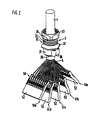
- the contact block 59 shown in FIG. 3 can likewise can be easily fanned out again like when assembling, so that the contact rows 58 of the individual, fanned out Contact carrier 51a to 51e - as shown in Fig. 2 - easily accessible for possible exchange of contacts are.
- the contact block 59 shown in FIG. 3 is like 4 shows - accommodated in a contact block container 63, which consists of an approximately U-shaped cross section first insulating part 63a and a plate-shaped second insulating part 63b.
- the first insulating part 63a has two side walls 64 which are in the region of the ends their front longitudinal edge, each with two locking holes 65 are provided, as well as one over the side walls 64 also extended rear wall 66 to support the contact block 59 on.
- the second plate-shaped insulating part 63b now serves as a cover for the open side of the contact block, i.e. as a cover of the open Contacts of the last contact carrier 51e and at the same time as the lid of the contact block container 63.
- the second Insulating part 63b has two parallel, in Longitudinal edges of the side bars 67 with two each according to the position of the locking holes 65 of the first insulating part 63a arranged locking lugs 68 on. These latches snap together when you put them together of the two insulating parts 63a and 63b the contact block container 63 into the locking holes 65.
- the contact block 59 is then through the second insulating part 63b held together and on its open side covered with insulation.
- the two insulating parts 63a and 63b of the contact block container 63 are - as with the insulating part 63b in 4 and 5 can be seen - in the area of their mating side (lower) end with polarization and Provide coding means.
- These funds are through in Ribs 69 and grooves 70 extending in the direction of insertion the outer surface 71 of the insulating part 63b or on the outer surface the rear wall 66 of the insulating part 63a and formed by strips 72 which can be inserted separately into the grooves.
- the contact block 59 and the container 63 form the complete module connector 5, which - as the Fig.5 shows and is already mentioned at the beginning - with the cable connection device 3 connected multi-core Cable 4 as a whole in the half-shell 2a of the connector housing 2 used and in this e.g. by means of Side walls 27 of the half-shell torn inwards Locking tongues 28 is kept locked. It is the pre-assembled with the cable connection device 3 Cable 4 inserted into the half-shell 2a so that the Flange 37 of the support sleeve 32 itself within this Half-shell, i.e. is located under the end wall 22.
- the union nut 33 is then screwed on, see above that the end walls 21,22 of the composite Half shells 2a and 2b of the connector housing 2 between the flange 37 of the support sleeve 32 and the screwed the threaded part 35 of the support sleeve Union nut 33 are firmly clamped. So that's it mechanical connection between the connector housing 2 and the cable connection device 3, being due to a corresponding clear outside width of the two diametrically opposite one another Collar 25,26 the cap nut 33 this collar overlaps. It is also screwed in place the union nut 33 the contacting of the cable shield made on the connector housing 2.
- the connector housing can also be made in one piece be the contact block with insulation then inserted into the open end of the connector housing becomes.
Landscapes
- Multi-Conductor Connections (AREA)
- Connector Housings Or Holding Contact Members (AREA)
- Coupling Device And Connection With Printed Circuit (AREA)
- Details Of Connecting Devices For Male And Female Coupling (AREA)
Claims (10)
- Connecteur (1) de câble pour câbles (4) multibrins, comportant un boítier (2) de connecteur et un connecteur (5) modulaire qui est introduit dans le boítier (2) de connecteur et qui est constitué de supports (51a à 51e) de contacts individuels, qui sont en forme de plaque en un matériau isolant, qui sont empilés en un bloc (59) de contact et, en l'occurrence, superposés directement et bloqués mutuellement les uns les autres dans la direction d'enfichage et qui sont munis chacun, sur la même surface extérieure (face 52 avant), de canaux (53) ouverts, s'étendant parallèlement les uns aux autres dans la direction d'enfichage, formés par des parois (55) de séparation parallèles et destinés aux contacts IDC (Insulation Displacement Connection) en vue du raccordement des brins (6) individuels de câbles,
caractérisé par les dispositions suivantes :a) le boítier de connecteur est électroconducteur,b) les supports (5 la à 51e) de contacts en forme de plaque sont munis sur la face (52) avant de canaux alignés sur les canaux (53) ouverts, fermés et s'étendant en direction du côté d'enfichage, pour le contact avec des tronçons enfichables des contacts IDC prévus pour le contact avec un élément de contact antagoniste,c) les supports (51a à 51e) de contacts sont empilés de telle manière qu'ils se trouvent entre la rangée (58) de contacts ménagée sur la face (52) avant d'un support de contacts (par exemple 51a) et la rangée (58) de contacts ménagée sur la face (52) avant d'un support (par exemple 51b) de contacts voisin, une surface extérieure de supports de contacts (face 57 arrière) continue, sans rangée de contacts, agissant comme paroi de séparation isolante.d) une pièce (63b) isolante en forme de plaque est prévue sur la face (52) avant ouverte du dernier support (52e) de contacts, pour recouvrir ses canaux (53) ouverts,e) la pièce (63b) isolante en forme de plaque comporte sur deux grands côtés parallèles l'un à l'autre et s'étendant dans la direction d'enfichage des barrettes (67) latérales et, par ces barrettes, peut être encliquetée avec les parois (64) latérales d'une autre pièce (63a) isolante de section transversale à peu près en forme de U et assemblée en le réceptacle (63) de bloc de contact qui maintient ensemble les supports (51a à 51e) de contacts en l'état empilé en le bloc (59) de contact,f) les pièces (63a, 63b) isolantes sont munies de moyens (69, 70, 72) de polarisation et de codage dans la zone de leur extrémité située du côté d'enfichage. - Connecteur de câble suivant la revendication 1, caractérisé en ce que les canaux (53) ouverts des rangées (58) de contact sont prévus dans la moitié supérieure (du côté de raccordement) des supports (51a à 51e) de contacts et en ce que les canaux fermés se raccordent en s'étendant dans l'épaisseur du matériau des supports de contacts.
- Connecteur de câble suivant la revendication 1, caractérisé en ce que les moyens de polarisation et de codage sont formés par des nervures (69) et des rainures (70) s'étendant dans la direction d'enfichage à la surface (71) extérieure des pièces (63a, 63b) isolantes, ainsi que par des baguettes (72) pouvant être insérées séparément dans les rainures (70).
- Connecteur de câble suivant l'une des revendications précédentes, caractérisé en ce que le bloc (59) de contact comporte des faces (60) latérales fermées.
- Connecteur de câble suivant la revendication 4, caractérisé en ce que les surfaces (60) latérales sont formées chacune par de minces barrettes (61) latérales, qui sont prévues sur deux grands côtés parallèles l'un à l'autre et s'étendant dans la direction d'enfichage, sur la face avant des supports (51a à 51e) de contacts individuels, et qui rentrent dans des renfoncements (61) correspondants ménagés sur la face (57) arrière d'un support de contacts voisin.
- Connecteur de câble suivant l'une des revendications précédentes, caractérisé en ce que les supports (51a à 51e) de contacts sont, pour le blocage dans la direction d'enfichage et transversalement à cette direction, réalisés en ayant sur la face (52) avant des parties (56) en saillie qui rentrent dans des évidements correspondants ménagés sur la face (57) arrière d'un support (51a à 51e) de contacts voisin.
- Connecteur de câble suivant la revendication 6, caractérisé en ce que les parties en saillie servant à bloquer les supports (5 la à 51e) de contacts sont formées par des nervures (56) dans la zone de la rangée (58) de contacts ménagée sur la face (52) avant des supports (51a à 51e) de contacts et en ce que les évidements sont formés par des rainures correspondantes ménagées sur la face (57) arrière des supports (51a à 51e) de contacts.
- Connecteur de câble suivant l'une des revendications précédentes, caractérisé en ce que le boítier (2) de câble est constitué de deux hémi-coquilles (2a, 2b) de section transversale à peu près en forme de U et en ce que le bloc (59) de contact comportant un isolant est introduit en entier dans une hémi-coquille (2a) et y est bloqué.
- Connecteur de câble suivant l'une des revendications 1 à 8, caractérisé en ce que le boítier de connecteur est réalisé d'un seul tenant et en ce que le bloc de contact comportant un isolant est enfilé dans la face frontale ouverte du boítier de connecteur.
- Connecteur de câble suivant l'une des revendications précédentes, caractérisé en ce qu'il est prévu pour le raccordement d'un câble (4) un dispositif (3) de raccordement de câble qui peut être relié mécaniquement à la paroi (21, 22) frontale du boítier (2) de connecteur et qui comprend une douille (32) de soutien comportant une bride (37) et une partie (35) filetée ainsi qu'un écrou-raccord (33).
Applications Claiming Priority (4)
| Application Number | Priority Date | Filing Date | Title |
|---|---|---|---|
| DE9214719U | 1992-10-29 | ||
| DE9214719U DE9214719U1 (de) | 1992-10-29 | 1992-10-29 | Geschirmter Stecker mit Kabelanschluß |
| DE9311781U DE9311781U1 (de) | 1992-10-29 | 1993-08-06 | Kabelstecker für vieladrige Kabel |
| DE9311781U | 1993-08-06 |
Publications (3)
| Publication Number | Publication Date |
|---|---|
| EP0595234A1 EP0595234A1 (fr) | 1994-05-04 |
| EP0595234B1 EP0595234B1 (fr) | 1998-04-29 |
| EP0595234B2 true EP0595234B2 (fr) | 2002-09-25 |
Family
ID=25960088
Family Applications (1)
| Application Number | Title | Priority Date | Filing Date |
|---|---|---|---|
| EP93117262A Expired - Lifetime EP0595234B2 (fr) | 1992-10-29 | 1993-10-25 | Connecteur de câble pour câbles multibrins |
Country Status (3)
| Country | Link |
|---|---|
| US (1) | US5368505A (fr) |
| EP (1) | EP0595234B2 (fr) |
| DE (2) | DE9311781U1 (fr) |
Families Citing this family (34)
| Publication number | Priority date | Publication date | Assignee | Title |
|---|---|---|---|---|
| DE4425466A1 (de) * | 1994-07-19 | 1996-01-25 | Thomas & Betts Gmbh | Kabel-Steckverbinder |
| JP2942979B2 (ja) * | 1994-11-21 | 1999-08-30 | モレックス インコーポレーテッド | 電気コネクタ |
| NL1000051C2 (nl) * | 1995-04-05 | 1996-10-08 | Framatome Connectors Belgium | Connector. |
| NL1000050C2 (nl) * | 1995-04-05 | 1996-10-08 | Framatome Connectors Belgium | Connector. |
| NL1000052C2 (nl) * | 1995-04-05 | 1996-10-08 | Framatome Connectors Belgium | Connector. |
| CA2232688C (fr) * | 1995-09-21 | 2002-08-13 | Siemens Aktiengesellschaft | Procede de raccordement d'un connecteur femelle multipolaire |
| US6036543A (en) * | 1996-04-04 | 2000-03-14 | Framatome Connectors International | Connector assembly |
| US5893778A (en) * | 1996-07-22 | 1999-04-13 | The Whitaker Corporation | Modular connector |
| DE19631152C1 (de) * | 1996-08-01 | 1998-01-02 | Siemens Ag | Vorrichtung zum Anschlagen von Einzelleitungen an IDC-Kontakte |
| US5997361A (en) * | 1997-06-30 | 1999-12-07 | Litton Systems, Inc. | Electronic cable connector |
| US6231392B1 (en) | 1997-10-01 | 2001-05-15 | Berg Technology, Inc. | Cable interconnection |
| US6106326A (en) * | 1998-05-27 | 2000-08-22 | Framatome Connectors Interlock, Inc. | Electrical connector with contact retaining module formed from reverse alternating modular frame pieces |
| DE19931728B4 (de) * | 1999-07-08 | 2009-07-30 | Intercontec Pfeiffer Industrie-Steckverbindungen Gmbh | Kontaktträger für vielpolige elektrische Steckverbinder |
| US6217364B1 (en) | 1999-07-09 | 2001-04-17 | Molex Incorporated | Electrical connector assembly with guide pin latching system |
| DE19950129A1 (de) * | 1999-10-18 | 2001-04-19 | Delphi Tech Inc | Mehrpoliges elektrisches Steckverbindungssystem |
| DE10018351C2 (de) * | 2000-04-13 | 2002-07-04 | Siemens Ag | Klemme |
| US6979215B2 (en) | 2001-11-28 | 2005-12-27 | Molex Incorporated | High-density connector assembly with flexural capabilities |
| US6746277B2 (en) | 2001-12-05 | 2004-06-08 | Tyco Electronics Corporation | Coaxial cable connector |
| US6746268B2 (en) | 2001-12-05 | 2004-06-08 | Tyco Electronics Corporation | Coaxial cable displacement contact |
| DE20203788U1 (de) * | 2002-03-08 | 2002-06-06 | Anton Hummel Verwaltungs Gmbh, 79183 Waldkirch | Steckverbinder mit einem Gehäuse und mit einem Klemmeinsatz |
| NL1026502C2 (nl) * | 2004-06-25 | 2005-12-28 | Framatome Connectors Int | Connector, connector-samenstelsysteem en werkwijze voor het samenstellen van een connector. |
| US7591655B2 (en) | 2006-08-02 | 2009-09-22 | Tyco Electronics Corporation | Electrical connector having improved electrical characteristics |
| US7753742B2 (en) | 2006-08-02 | 2010-07-13 | Tyco Electronics Corporation | Electrical terminal having improved insertion characteristics and electrical connector for use therewith |
| US8142236B2 (en) | 2006-08-02 | 2012-03-27 | Tyco Electronics Corporation | Electrical connector having improved density and routing characteristics and related methods |
| US7670196B2 (en) | 2006-08-02 | 2010-03-02 | Tyco Electronics Corporation | Electrical terminal having tactile feedback tip and electrical connector for use therewith |
| US7549897B2 (en) | 2006-08-02 | 2009-06-23 | Tyco Electronics Corporation | Electrical connector having improved terminal configuration |
| DE202008015308U1 (de) * | 2008-11-19 | 2010-04-08 | Weidmüller Interface GmbH & Co. KG | Rundsteckverbinder |
| DE202009007276U1 (de) * | 2009-05-22 | 2010-10-14 | Weidmüller Interface GmbH & Co. KG | Steckverbinder zum Übertragen hoher elektrischer Leistungen |
| CN201498780U (zh) * | 2009-06-26 | 2010-06-02 | 富士康(昆山)电脑接插件有限公司 | 线缆连接器组件 |
| DE102011009929B4 (de) | 2010-02-01 | 2018-05-17 | Sew-Eurodrive Gmbh & Co Kg | Steckverbinderteil |
| JP2013137922A (ja) * | 2011-12-28 | 2013-07-11 | Tyco Electronics Japan Kk | 電気コネクタ |
| CN104810659A (zh) * | 2014-01-24 | 2015-07-29 | 富士康(昆山)电脑接插件有限公司 | 线缆连接器 |
| US10128611B2 (en) * | 2016-08-01 | 2018-11-13 | Te Connectivity Corporation | Ferrule assembly for an electrical connector |
| JP7129010B2 (ja) * | 2018-12-21 | 2022-09-01 | 株式会社オートネットワーク技術研究所 | コネクタ構造体 |
Citations (4)
| Publication number | Priority date | Publication date | Assignee | Title |
|---|---|---|---|---|
| GB1121742A (en) † | 1964-12-17 | 1968-07-31 | Western Electric Co | Electrical coupler for multiconducting cables and a method of coupling such cables |
| DE9100441U1 (de) † | 1991-01-15 | 1992-05-21 | Grote & Hartmann Gmbh & Co Kg, 5600 Wuppertal | Elektrisches Steckgehäuse |
| DE9214719U1 (de) † | 1992-10-29 | 1992-12-17 | Siemens AG, 8000 München | Geschirmter Stecker mit Kabelanschluß |
| DE9311778U1 (de) † | 1993-08-06 | 1994-12-08 | Liebherr-Werk Ehingen Gmbh, 89584 Ehingen | Mobilkran |
Family Cites Families (7)
| Publication number | Priority date | Publication date | Assignee | Title |
|---|---|---|---|---|
| US3072340A (en) * | 1960-09-16 | 1963-01-08 | Cannon Electric Co | Electrical connector insulator block construction |
| US3447036A (en) * | 1967-04-21 | 1969-05-27 | Bell Telephone Labor Inc | Assembly for mounting and aligning modules |
| JPS59184476U (ja) * | 1983-05-25 | 1984-12-07 | 住友電装株式会社 | コネクタハウジング |
| US4550960A (en) * | 1984-08-24 | 1985-11-05 | Amp Incorporated | Shielded backplane assembly |
| US4734054A (en) * | 1985-07-08 | 1988-03-29 | Siemens Aktiengesellschaft | Plug connector |
| US5108313A (en) * | 1989-10-05 | 1992-04-28 | E. I. Du Pont De Nemours And Company | Modular connector |
| DE9207674U1 (de) * | 1992-06-05 | 1992-08-20 | Siemens AG, 8000 München | Stecker für ein geschirmtes Übergabesystem |
-
1993
- 1993-08-06 DE DE9311781U patent/DE9311781U1/de not_active Expired - Lifetime
- 1993-10-25 DE DE59308467T patent/DE59308467D1/de not_active Expired - Lifetime
- 1993-10-25 EP EP93117262A patent/EP0595234B2/fr not_active Expired - Lifetime
- 1993-10-29 US US08/145,464 patent/US5368505A/en not_active Expired - Lifetime
Patent Citations (4)
| Publication number | Priority date | Publication date | Assignee | Title |
|---|---|---|---|---|
| GB1121742A (en) † | 1964-12-17 | 1968-07-31 | Western Electric Co | Electrical coupler for multiconducting cables and a method of coupling such cables |
| DE9100441U1 (de) † | 1991-01-15 | 1992-05-21 | Grote & Hartmann Gmbh & Co Kg, 5600 Wuppertal | Elektrisches Steckgehäuse |
| DE9214719U1 (de) † | 1992-10-29 | 1992-12-17 | Siemens AG, 8000 München | Geschirmter Stecker mit Kabelanschluß |
| DE9311778U1 (de) † | 1993-08-06 | 1994-12-08 | Liebherr-Werk Ehingen Gmbh, 89584 Ehingen | Mobilkran |
Non-Patent Citations (1)
| Title |
|---|
| AMP Katalog Connectors D/E-5 8/88 † |
Also Published As
| Publication number | Publication date |
|---|---|
| US5368505A (en) | 1994-11-29 |
| DE9311781U1 (de) | 1993-09-30 |
| DE59308467D1 (de) | 1998-06-04 |
| EP0595234A1 (fr) | 1994-05-04 |
| EP0595234B1 (fr) | 1998-04-29 |
Similar Documents
| Publication | Publication Date | Title |
|---|---|---|
| EP0595234B2 (fr) | Connecteur de câble pour câbles multibrins | |
| DE3828872C2 (de) | Elektrischer Steckverbinder | |
| DE2224326C2 (de) | Elektrischer Steckverbinder | |
| DE69504474T2 (de) | Elektrischer verbinder, gehäuse und kontakt | |
| DE102011076566B4 (de) | Masseverbindungsvorrichtung und kabelbaum mit derselben | |
| DE69320598T2 (de) | Verbinder | |
| DE69601754T2 (de) | Anschlusselement und Klemmverbinder | |
| DE69900770T2 (de) | Elektrischer Verbinder mit seitlicher Verriegelung | |
| DE69315727T2 (de) | Hybrider Eingangs-Ausgangsverbinder mit schwacher Einrückungskraft und langer Lebensdauer und Kontakten und Verriegelungssystem dafür | |
| DE69515946T2 (de) | Polarisationselemente für elektrisches Verbindersystem mit Einsteckhilfe | |
| DE3780065T2 (de) | Aufbau eines abgeschirmten kabels. | |
| DE102013220348B4 (de) | Relais, Relaismodul und elektrische Anschlussdose | |
| DE2651525C2 (fr) | ||
| DE2743759A1 (de) | Anschlussystem fuer elektrische leiter | |
| DE2536135A1 (de) | Elektrische verbindungsanordnung | |
| DE3854593T2 (de) | Elektrische Steckverbindung, am Kabelende angeschlossen und ausgestattet mit Mitteln zur Verringerung der Zugkraft, die auf das Kabel und durch das Kabel wirkt. | |
| DE4011958C2 (fr) | ||
| DE69924667T2 (de) | Eine Vorrichtung zur Verhinderung einer fehlerhaften Zusammensetzung eines Verbindergehäuses mit einem Deckel und einen Verbinder mit einer solchen Vorrichtung | |
| DE69836598T2 (de) | Elektrischer Verbindungskasten und dazugehöriges Fahrzeug | |
| DE69503788T2 (de) | Steckverbinder für ein elektrisches kabel | |
| DE4106412C2 (de) | Elektrischer Steckverbinder | |
| EP1744404B2 (fr) | Dispositif de connexion et système de connexion pour conducteurs électriques isolés | |
| DE102018215088A1 (de) | Verbinder | |
| DE69413524T2 (de) | Querverbindungssystem für Telekommunikationssysteme | |
| DE10223271B4 (de) | Steckverbinder |
Legal Events
| Date | Code | Title | Description |
|---|---|---|---|
| PUAI | Public reference made under article 153(3) epc to a published international application that has entered the european phase |
Free format text: ORIGINAL CODE: 0009012 |
|
| AK | Designated contracting states |
Kind code of ref document: A1 Designated state(s): CH DE FR GB IT LI SE |
|
| 17P | Request for examination filed |
Effective date: 19940707 |
|
| 17Q | First examination report despatched |
Effective date: 19960116 |
|
| GRAG | Despatch of communication of intention to grant |
Free format text: ORIGINAL CODE: EPIDOS AGRA |
|
| GRAG | Despatch of communication of intention to grant |
Free format text: ORIGINAL CODE: EPIDOS AGRA |
|
| GRAH | Despatch of communication of intention to grant a patent |
Free format text: ORIGINAL CODE: EPIDOS IGRA |
|
| GRAH | Despatch of communication of intention to grant a patent |
Free format text: ORIGINAL CODE: EPIDOS IGRA |
|
| GRAA | (expected) grant |
Free format text: ORIGINAL CODE: 0009210 |
|
| AK | Designated contracting states |
Kind code of ref document: B1 Designated state(s): CH DE FR GB IT LI SE |
|
| REG | Reference to a national code |
Ref country code: CH Ref legal event code: NV Representative=s name: SIEMENS SCHWEIZ AG Ref country code: CH Ref legal event code: EP |
|
| REF | Corresponds to: |
Ref document number: 59308467 Country of ref document: DE Date of ref document: 19980604 |
|
| ET | Fr: translation filed | ||
| ITF | It: translation for a ep patent filed | ||
| GBT | Gb: translation of ep patent filed (gb section 77(6)(a)/1977) |
Effective date: 19980630 |
|
| PLAV | Examination of admissibility of opposition |
Free format text: ORIGINAL CODE: EPIDOS OPEX |
|
| PLBQ | Unpublished change to opponent data |
Free format text: ORIGINAL CODE: EPIDOS OPPO |
|
| PLBI | Opposition filed |
Free format text: ORIGINAL CODE: 0009260 |
|
| PLAV | Examination of admissibility of opposition |
Free format text: ORIGINAL CODE: EPIDOS OPEX |
|
| PLBF | Reply of patent proprietor to notice(s) of opposition |
Free format text: ORIGINAL CODE: EPIDOS OBSO |
|
| 26 | Opposition filed |
Opponent name: GROTE & HARTMANN GMBH & CO. KG Effective date: 19990119 |
|
| PLBF | Reply of patent proprietor to notice(s) of opposition |
Free format text: ORIGINAL CODE: EPIDOS OBSO |
|
| PLBF | Reply of patent proprietor to notice(s) of opposition |
Free format text: ORIGINAL CODE: EPIDOS OBSO |
|
| RDAH | Patent revoked |
Free format text: ORIGINAL CODE: EPIDOS REVO |
|
| APAC | Appeal dossier modified |
Free format text: ORIGINAL CODE: EPIDOS NOAPO |
|
| APAE | Appeal reference modified |
Free format text: ORIGINAL CODE: EPIDOS REFNO |
|
| APAC | Appeal dossier modified |
Free format text: ORIGINAL CODE: EPIDOS NOAPO |
|
| REG | Reference to a national code |
Ref country code: CH Ref legal event code: PUE Owner name: SIEMENS AKTIENGESELLSCHAFT TRANSFER- TYCO ELECTRON Ref country code: CH Ref legal event code: NV Representative=s name: RIEDERER HASLER & PARTNER PATENTANWAELTE AG |
|
| RAP2 | Party data changed (patent owner data changed or rights of a patent transferred) |
Owner name: TYCO ELECTRONICS LOGISTICS AG |
|
| RAP2 | Party data changed (patent owner data changed or rights of a patent transferred) |
Owner name: SIEMENS AKTIENGESELLSCHAFT |
|
| REG | Reference to a national code |
Ref country code: GB Ref legal event code: 732E |
|
| RAP2 | Party data changed (patent owner data changed or rights of a patent transferred) |
Owner name: TYCO ELECTRONICS LOGISTICS AG |
|
| REG | Reference to a national code |
Ref country code: GB Ref legal event code: IF02 |
|
| APAC | Appeal dossier modified |
Free format text: ORIGINAL CODE: EPIDOS NOAPO |
|
| PLAW | Interlocutory decision in opposition |
Free format text: ORIGINAL CODE: EPIDOS IDOP |
|
| PUAH | Patent maintained in amended form |
Free format text: ORIGINAL CODE: 0009272 |
|
| STAA | Information on the status of an ep patent application or granted ep patent |
Free format text: STATUS: PATENT MAINTAINED AS AMENDED |
|
| 27A | Patent maintained in amended form |
Effective date: 20020925 |
|
| AK | Designated contracting states |
Kind code of ref document: B2 Designated state(s): CH DE FR GB IT LI SE |
|
| REG | Reference to a national code |
Ref country code: CH Ref legal event code: AEN Free format text: AUFRECHTERHALTUNG DES PATENTES IN GEAENDERTER FORM |
|
| REG | Reference to a national code |
Ref country code: CH Ref legal event code: NV Representative=s name: RITSCHER & PARTNER AG PATENTANWAELTE |
|
| GBTA | Gb: translation of amended ep patent filed (gb section 77(6)(b)/1977) | ||
| ET3 | Fr: translation filed ** decision concerning opposition | ||
| APAH | Appeal reference modified |
Free format text: ORIGINAL CODE: EPIDOSCREFNO |
|
| REG | Reference to a national code |
Ref country code: CH Ref legal event code: PCAR Free format text: RITSCHER & PARTNER AG;RESIRAIN 1;8125 ZOLLIKERBERG (CH) |
|
| PGFP | Annual fee paid to national office [announced via postgrant information from national office to epo] |
Ref country code: CH Payment date: 20121025 Year of fee payment: 20 Ref country code: DE Payment date: 20121029 Year of fee payment: 20 Ref country code: FR Payment date: 20121107 Year of fee payment: 20 |
|
| PGFP | Annual fee paid to national office [announced via postgrant information from national office to epo] |
Ref country code: GB Payment date: 20121025 Year of fee payment: 20 Ref country code: SE Payment date: 20121029 Year of fee payment: 20 Ref country code: IT Payment date: 20121024 Year of fee payment: 20 |
|
| REG | Reference to a national code |
Ref country code: DE Ref legal event code: R071 Ref document number: 59308467 Country of ref document: DE |
|
| REG | Reference to a national code |
Ref country code: CH Ref legal event code: PL |
|
| REG | Reference to a national code |
Ref country code: GB Ref legal event code: PE20 Expiry date: 20131024 |
|
| REG | Reference to a national code |
Ref country code: SE Ref legal event code: EUG |
|
| PG25 | Lapsed in a contracting state [announced via postgrant information from national office to epo] |
Ref country code: GB Free format text: LAPSE BECAUSE OF EXPIRATION OF PROTECTION Effective date: 20131024 Ref country code: DE Free format text: LAPSE BECAUSE OF EXPIRATION OF PROTECTION Effective date: 20131026 |