EP0595314B1 - Procédé pour l'accord d'un récepteur radio - Google Patents
Procédé pour l'accord d'un récepteur radio Download PDFInfo
- Publication number
- EP0595314B1 EP0595314B1 EP93117483A EP93117483A EP0595314B1 EP 0595314 B1 EP0595314 B1 EP 0595314B1 EP 93117483 A EP93117483 A EP 93117483A EP 93117483 A EP93117483 A EP 93117483A EP 0595314 B1 EP0595314 B1 EP 0595314B1
- Authority
- EP
- European Patent Office
- Prior art keywords
- frequency
- alternative
- receive section
- tuned
- tuning
- Prior art date
- Legal status (The legal status is an assumption and is not a legal conclusion. Google has not performed a legal analysis and makes no representation as to the accuracy of the status listed.)
- Expired - Lifetime
Links
Images

Classifications
-
- H—ELECTRICITY
- H04—ELECTRIC COMMUNICATION TECHNIQUE
- H04H—BROADCAST COMMUNICATION
- H04H20/00—Arrangements for broadcast or for distribution combined with broadcast
- H04H20/20—Arrangements for broadcast or distribution of identical information via plural systems
- H04H20/22—Arrangements for broadcast of identical information via plural broadcast systems
-
- H—ELECTRICITY
- H03—ELECTRONIC CIRCUITRY
- H03J—TUNING RESONANT CIRCUITS; SELECTING RESONANT CIRCUITS
- H03J1/00—Details of adjusting, driving, indicating, or mechanical control arrangements for resonant circuits in general
- H03J1/0008—Details of adjusting, driving, indicating, or mechanical control arrangements for resonant circuits in general using a central processing unit, e.g. a microprocessor
- H03J1/0058—Details of adjusting, driving, indicating, or mechanical control arrangements for resonant circuits in general using a central processing unit, e.g. a microprocessor provided with channel identification means
- H03J1/0083—Details of adjusting, driving, indicating, or mechanical control arrangements for resonant circuits in general using a central processing unit, e.g. a microprocessor provided with channel identification means using two or more tuners
-
- H—ELECTRICITY
- H04—ELECTRIC COMMUNICATION TECHNIQUE
- H04H—BROADCAST COMMUNICATION
- H04H20/00—Arrangements for broadcast or for distribution combined with broadcast
- H04H20/26—Arrangements for switching distribution systems
-
- H—ELECTRICITY
- H04—ELECTRIC COMMUNICATION TECHNIQUE
- H04H—BROADCAST COMMUNICATION
- H04H2201/00—Aspects of broadcast communication
- H04H2201/10—Aspects of broadcast communication characterised by the type of broadcast system
- H04H2201/13—Aspects of broadcast communication characterised by the type of broadcast system radio data system/radio broadcast data system [RDS/RBDS]
Definitions
- the invention relates to a method for tuning a radio receiver, which has two superhet receiving parts, the first of which the one tuned stations received signals for playback via transducers processed and the second at least if necessary for available alternative frequencies is tuned to the tuned station and which the Reception quality resulting alternative frequencies evaluated.
- Particularly powerful radio receivers for mobile operation such as car radios, are equipped with frequency diversity and have two separate receiving parts, of which the first as a hearing receiver and the second is referred to as a search recipient.
- the search receiver mostly works in Channel search to find the reception area according to alternative frequencies Search for the station frequency to which the hearing receiver is currently set.
- searching the search receiver across the entire FM reception range from 87.5 to 108 MHz and at a common intermediate frequency of 10.7 MHz the local oscillator of the search receiver would inevitably be in the range of Frequency to which the hearing receiver is set. Through inevitable Radiation and coupling within the radio receiver would in in this case the reception of the set station can be disturbed.
- an alternative frequency is checked whether the one required for this alternative frequency Oscillator frequency of the second receiving part in on the frequency of tuned transmitter falls centered frequency band of predetermined width, and each alternative frequency falling in this frequency band is at the Tuning of the second receiver part skipped
- a method is known from DE-A-3 443 859.
- the invention is based, without accepting interference, the task the use of receiving parts in single super heterodyne technology for radio receivers operated in frequency diversity, and thereby no loss in the performance of the frequency diversity function to have to put up with.
- This object is achieved by the two variants of the invention, which are defined by claims 1 and 2.
- the second receiving part is tuned checked for an alternative frequency whether this alternative frequency in a frequency band centered on the current oscillator frequency of the first receiving part of predetermined width, and each falls in this frequency band falling alternative frequency is when tuning the second receiving part ignored or at least with regard to the for this alternative frequency received quality assessment not taken into account. If namely the oscillator frequency of the first receiving part, that is, the hearing receiver, into the area the frequency falls on which the second receiving part, i.e. the search receiver, is currently tuned, so will the reception of this second receiving part disturbed, so that a reliable evaluation of the reception quality is not possible is.
- the Reception quality of an alternative frequency that is based on the current oscillator frequency of the first receiving part centered frequency band of predetermined Width falls, the first receiving part at least temporarily to one of the alternative frequencies. Then the second receiving part be tuned to the alternative frequency to be checked without Reception disturbances are to be feared.
- the second receiving part that is to say the search receiver
- the search receiver is preferred not continuously tuned in the search, but only for certain ones Alternative frequencies to the transmitter currently set on the first receiver, which are derived from the RDS data stream. This allows a quick one Checking all alternative frequencies in question, so that in principle only a slight probability of interference to the hearing receiver by the Search recipient exists.
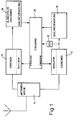
- the radio receiver shown schematically in Fig. 1 is a car radio two receiving parts that allow operation in frequency diversity.
- the Both receiving parts 10 and 12 of the radio receiver are connected to an antenna switch 14 connected.
- the receiving part 10 forms the hearing receiver, the Output is connected to an LF stage 16, the filters for sound adjustment, Power amplifier and a quality evaluation circuit includes.
- the receiving part 12 is a search receiver, the output of which is at a quality evaluation level 18 is connected.
- the functions of the two receiving parts 10, 12 are by a control circuit equipped with a microprocessor 20 controlled.
- This control circuit 20 controls in particular the frequency of the local oscillators of the receiving parts 10, 12. It evaluates those from the NF level 16 and quality evaluation information obtained from the quality evaluation circuit 18 out.
- the control circuit 20 also receives an RDS decoder 22 the information obtained from the RDS data stream available alternative frequencies to the transmitter to which the receiving part 10 is set.
- the reception area of the two reception parts shown in FIGS. 2 and 3 of the radio receiver extends in the FM band from 87.5 to 108.0 MHz.
- the inventive method is at a distance below the Tuning frequency of the hearing receiver 10, which is equal to the intermediate frequency, with which of these receivers works, usually 10.7 MHz, is a prohibited one Defined area of predetermined width.
- This prohibited area is in Fig. 2 and hatched in Fig. 3 and labeled A.
- the forbidden one Area A has a width of several 100 kilohertz and corresponds to in about the width of the IF passband of the hearing receiver 10.
- the RDS decoder 22 provides information about alternative frequencies to this Transmitter evaluated by the control circuit 20, the search receiver 12th by controlling the frequency of its local oscillator one after the other Alternative frequencies are tuned to the different alternative frequencies to determine the resulting reception quality.
- the control circuit 20 checks whether they are in the prohibited area A would fall. If an alternative frequency in the forbidden area A, the search recipient does not vote this frequency. When the search receiver is tuned to a frequency within the prohibited area A would be due to inevitable Radiations and couplings inside the radio receiver interference of the hearing receiver 10 occur.
- the function of the search receiver 12 can in turn by irradiation from the Local oscillator of the hearing receiver 10 are disturbed when the alternative frequency, to which the search receiver 12 is matched, in the area of current oscillator frequency of the hearing receiver 10 arrives. Therefore, as in Fig. 3, further defines a second prohibited area, which with B is labeled and hatched. It lies at a distance from the Tuning frequency of the hearing receiver 10, which is equal to the intermediate frequency, is normally 10.7 MHz, and has about the same width as that prohibited area A. So before the search receiver 12 on an alternative frequency is checked, it is checked whether this is in the prohibited area B would fall. If this is the case, the search recipient is not reconciled 12 on this frequency. This prevents reception interference the recipient of the search for an incorrect quality assessment of certain Lead alternative frequencies.
- the hearing receiver will be able to check the alternative frequencies taken 10, as soon as the search receiver 12 is to check an alternative frequency, which in would fall into a prohibited area, at least temporarily on one of the available alternative frequencies matched, preferably the one offers the best possible reception quality.
- Both receiving parts 10 and 12 are designed in single super heterodyne technology and work with the usual intermediate frequency of 10.7 MHz.
Landscapes
- Engineering & Computer Science (AREA)
- Signal Processing (AREA)
- Computer Hardware Design (AREA)
- Microelectronics & Electronic Packaging (AREA)
- Radio Transmission System (AREA)
- Circuits Of Receivers In General (AREA)
Claims (3)
- Procédé pour accorder un récepteur radio qui présente deux étages récepteurs (10, 12) superhétérodynes dont le premier étage récepteur (10) conditionne les signaux reçus par la station sur laquelle il a été accordé pour la reproduction par transducteurs acoustiques et le second étage récepteur (12) est accordé, au moins en cas de besoin, sur des fréquences alternatives, dans lequelcaractérisé en ce queon vérifie, avant de procéder à l'accord du second étage récepteur (12) sur une fréquence alternative, si la fréquence oscillatoire du second étage récepteur (12), nécessaire à cette fréquence alternative, tombe dans une bande de fréquence de largeur prédéterminée centrée sur la fréquence de la station choisie etchaque fréquence alternative ayant une fréquence oscillatoire tombant dans cette bande de fréquence est évitée lorsqu'on accorde le second étage récepteur (12),le second étage récepteur (12) est accordé sur des fréquences alternatives par rapport à la station choisie,la qualité de réception résultant des fréquences alternatives est évaluée, etavant l'accord du second étage récepteur (12) sur une fréquence alternative, il est encore vérifié si cette fréquence alternative tombe dans une bande de fréquence (B) de largeur prédéterminée, centrée sur la fréquence oscillatoire actuelle du premier étage récepteur (10), etavant la vérification de la qualité de réception d'une fréquence alternative, qui tombe dans cette bande de fréquence (B), le premier étage récepteur (10) est accordé au moins provisoirement sur une dedites fréquences alternatives.
- Procédé pour accorder un récepteur radio qui présente deux étages récepteurs (10, 12) superhétérodynes dont le premier étage récepteur (10) conditionne les signaux reçus par la station sur laquelle il a été accordé pour la reproduction par transducteurs acoustiques et le second étage récepteur (12) est accordé, au moins en cas de besoin, sur des fréquences alternatives, dans lequelcaractérisé en ce queon vérifie, avant de procéder à l'accord du second étage récepteur (12) sur une fréquence alternative, si la fréquence oscillatoire du second étage récepteur (12), nécessaire à cette fréquence alternative, tombe dans une bande de fréquence de largeur prédéterminée centrée sur la fréquence de la station choisie etchaque fréquence alternative ayant une fréquence oscillatoire tombant dans cette bande de fréquence est évitée lorsqu'on accorde le second étage récepteur (12),le second étage récepteur (12) est accordé sur des fréquences alternatives par rapport à la station choisie,la qualité de réception résultant des fréquences alternatives est évaluée etavant l'accord du second étage récepteur (12) sur une fréquence alternative, il est encore vérifié si cette fréquence alternative tombe dans une bande de fréquence (B) de largeur prédéterminée, centrée sur la fréquence oscillatoire actuelle du premier étage récepteur (10), etchaque fréquence alternative tombant dans cette bande de fréquence (B) est évitée lors de l'accord du second étage récepteur (12)ou l'évaluation de qualité obtenue pour cette fréquence alternative n'est pas prise en compte.
- Procédé selon l'une quelconque des revendications précédentes, caractérisé en ce que les fréquences alternatives sont dérivées du flux de données RDS et en ce que le second étage récepteur (12) n'est accordé que sur des valeurs de fréquence qui coïncident avec une desdites fréquences alternatives.
Applications Claiming Priority (2)
| Application Number | Priority Date | Filing Date | Title |
|---|---|---|---|
| DE4236621A DE4236621A1 (de) | 1992-10-29 | 1992-10-29 | Verfahren zur Abstimmung eines Rundfunkempfängers |
| DE4236621 | 1992-10-29 |
Publications (2)
| Publication Number | Publication Date |
|---|---|
| EP0595314A1 EP0595314A1 (fr) | 1994-05-04 |
| EP0595314B1 true EP0595314B1 (fr) | 1999-02-03 |
Family
ID=6471697
Family Applications (1)
| Application Number | Title | Priority Date | Filing Date |
|---|---|---|---|
| EP93117483A Expired - Lifetime EP0595314B1 (fr) | 1992-10-29 | 1993-10-28 | Procédé pour l'accord d'un récepteur radio |
Country Status (2)
| Country | Link |
|---|---|
| EP (1) | EP0595314B1 (fr) |
| DE (2) | DE4236621A1 (fr) |
Cited By (1)
| Publication number | Priority date | Publication date | Assignee | Title |
|---|---|---|---|---|
| EP2133312A1 (fr) | 2008-06-11 | 2009-12-16 | Fränkische Rohrwerke Gebr. Kirchner GmbH & Co. | Elément de support de biofilm, utilisation de tels éléments de support pour le nettoyage d'eau et filtre doté de tels éléments de support |
Families Citing this family (18)
| Publication number | Priority date | Publication date | Assignee | Title |
|---|---|---|---|---|
| US5812937B1 (en) * | 1993-04-08 | 2000-09-19 | Digital Dj Inc | Broadcast data system with multiple-tuner receiver |
| DE19503540A1 (de) * | 1995-02-03 | 1996-09-05 | Bosch Gmbh Robert | Verfahren zum Empfang und zur Ausgabe eines Rundfunkprogrammes mit zugefügten digitalen Informationen und Rundfunkempfängern dazu |
| DE19622432C2 (de) * | 1996-06-04 | 1999-05-12 | Rundfunkschutzrechte Ev | Funkempfänger mit einem Stationsspeicher |
| JP3702551B2 (ja) * | 1996-09-13 | 2005-10-05 | 住友電装株式会社 | 放送受信システム及びこれを利用した放送受信方法 |
| KR100699310B1 (ko) * | 1997-01-15 | 2007-06-04 | 코닌클리케 필립스 일렉트로닉스 엔.브이. | 멀티튜너수신기 |
| SG55266A1 (en) * | 1997-01-15 | 1999-04-27 | Koninkl Philips Electronics Nv | Multi-tuner receiver |
| US6272191B1 (en) | 1997-09-09 | 2001-08-07 | Sumitomo Wiring Systems, Ltd. | Information receiving system and an information receiving method using such a system |
| JP3606420B2 (ja) * | 1997-10-15 | 2005-01-05 | パイオニア株式会社 | 併設チューナを有するデータ多重放送受信機 |
| US7127010B1 (en) * | 1999-07-29 | 2006-10-24 | Bose Corporation | Oscillator controlling |
| DE10034039A1 (de) * | 2000-07-13 | 2002-01-31 | Harman Becker Automotive Sys | Runddfunkempfangssystem, Empfänger und Betriebsverfahren dafür |
| US7747232B2 (en) | 2001-07-13 | 2010-06-29 | Harman Becker Automotive Systems Gmbh | Radio reception system with automatic tuning |
| DE10218697A1 (de) * | 2002-04-26 | 2003-11-06 | Bosch Gmbh Robert | Mehrkanal-Funkempfänger |
| DE10354521A1 (de) | 2003-11-14 | 2005-06-23 | Atmel Germany Gmbh | Verfahren zur Synchronisation mehrerer Oszillatoren |
| DE102004041246A1 (de) * | 2004-08-26 | 2006-03-02 | Robert Bosch Gmbh | Rundfunkempfänger |
| US7783259B2 (en) | 2004-09-28 | 2010-08-24 | Microtune (Texas), L.P. | System and method of eliminating or minimizing LO-related interference from tuners |
| US7904024B2 (en) | 2004-09-28 | 2011-03-08 | Zoran Corporation | System and method of eliminating or minimizing Lo-Related interference from tuners |
| JP2007288631A (ja) * | 2006-04-19 | 2007-11-01 | Sony Corp | ダイバーシティ受信機 |
| US20080146165A1 (en) * | 2006-12-15 | 2008-06-19 | Motorola, Inc. | Dynamic frequency synthesizer programming |
Family Cites Families (4)
| Publication number | Priority date | Publication date | Assignee | Title |
|---|---|---|---|---|
| JPS60117927A (ja) * | 1983-11-30 | 1985-06-25 | Clarion Co Ltd | シンセサイザ受信機 |
| DE3507865A1 (de) * | 1985-03-06 | 1986-09-11 | Philips Patentverwaltung Gmbh, 2000 Hamburg | Schaltungsanordnung fuer einen tuner zur umschaltung mehrerer frequenzbereiche |
| JP2760552B2 (ja) * | 1988-03-17 | 1998-06-04 | 三洋電機株式会社 | 受信機 |
| JPH03293824A (ja) * | 1990-04-12 | 1991-12-25 | Pioneer Electron Corp | ラジオ受信機 |
-
1992
- 1992-10-29 DE DE4236621A patent/DE4236621A1/de not_active Withdrawn
-
1993
- 1993-10-28 EP EP93117483A patent/EP0595314B1/fr not_active Expired - Lifetime
- 1993-10-28 DE DE59309359T patent/DE59309359D1/de not_active Expired - Lifetime
Cited By (2)
| Publication number | Priority date | Publication date | Assignee | Title |
|---|---|---|---|---|
| EP2133312A1 (fr) | 2008-06-11 | 2009-12-16 | Fränkische Rohrwerke Gebr. Kirchner GmbH & Co. | Elément de support de biofilm, utilisation de tels éléments de support pour le nettoyage d'eau et filtre doté de tels éléments de support |
| DE102008027789A1 (de) | 2008-06-11 | 2009-12-17 | Fränkische Rohrwerke Gebr. Kirchner Gmbh & Co. Kg | Biofilm-Trägerelement, Verwendung derartiger Trägerelemente zur Reinigung von Wasser und Filter mit derartigen Trägerelementen |
Also Published As
| Publication number | Publication date |
|---|---|
| EP0595314A1 (fr) | 1994-05-04 |
| DE59309359D1 (de) | 1999-03-18 |
| DE4236621A1 (de) | 1994-05-05 |
Similar Documents
| Publication | Publication Date | Title |
|---|---|---|
| EP0595314B1 (fr) | Procédé pour l'accord d'un récepteur radio | |
| EP0561117B1 (fr) | Circuit pour détecter et supprimer l'interférence des canaux adjacents dans un récepteur de radiodiffusion | |
| DE4319457C2 (de) | Schaltungsanordnung zur Nachbarkanalerkennung und -unterdrückung in einem FM-Rundfunkempfänger | |
| DE69023100T2 (de) | Schaltung zur Signalqualitätsbestimmung für FM-Empfänger. | |
| DE69206826T2 (de) | Nachbarkanal-steuereinheit für funkempfänger | |
| DE69208667T2 (de) | Intermodulationssteuervorrichtung für einen Rundfunkempfänger | |
| EP0443170A2 (fr) | Procédé et dispositif pour commutation de largeur de bande | |
| EP0502500B1 (fr) | Méthode pour l'accord d'un récepteur radio, utilisant des information RDS | |
| EP0602370B1 (fr) | Récepteur radio | |
| EP0364749B1 (fr) | Récepteur radio | |
| DE2842309A1 (de) | Fernsehsignalverarbeitungskreis | |
| DE69832317T2 (de) | Funkempfänger und Verfahren zur Empfindlichkeitsregelung der AGC-Schleife | |
| EP0372369A2 (fr) | Circuit de réduction de signaux de bruit à bande étroite | |
| DE3818752A1 (de) | Fm-empfangsteil | |
| DE60037722T2 (de) | AM Empfänger | |
| DE3725487C2 (de) | Verfahren zum empfangsseitigen Auswerten einer innerhalb eines Rundfunksignals übertragenen digitalen Information | |
| DE2643570A1 (de) | Funkempfaenger | |
| DE3153411C2 (en) | Multi-station receiver with muting circuit | |
| EP0411485B1 (fr) | Procédé pour détecter des distortions multivoies lors de la réception radio à modulation de fréquence, et montage pour réaliser ce procédé | |
| EP0793361A1 (fr) | Circuit pour décoder des informations supplémentaires dans une transmission de radiodiffusion | |
| DE4239759C2 (de) | Verfahren zum Umschalten auf eine empfangswürdige Alternativfrequenz eines RDS-Empfängers | |
| DE3938269C1 (fr) | ||
| EP0670643B1 (fr) | Méthode et dispositif de synchronisation numérique du frâme | |
| EP1271816A2 (fr) | Procédé de recherche d'une fréquence dans un récepteur radio | |
| EP0739550A1 (fr) | Procede et circuits pour la reception d'emissions de radiodiffusion |
Legal Events
| Date | Code | Title | Description |
|---|---|---|---|
| PUAI | Public reference made under article 153(3) epc to a published international application that has entered the european phase |
Free format text: ORIGINAL CODE: 0009012 |
|
| AK | Designated contracting states |
Kind code of ref document: A1 Designated state(s): DE ES FR GB IT NL PT |
|
| 17P | Request for examination filed |
Effective date: 19941026 |
|
| 17Q | First examination report despatched |
Effective date: 19961104 |
|
| GRAG | Despatch of communication of intention to grant |
Free format text: ORIGINAL CODE: EPIDOS AGRA |
|
| GRAG | Despatch of communication of intention to grant |
Free format text: ORIGINAL CODE: EPIDOS AGRA |
|
| GRAH | Despatch of communication of intention to grant a patent |
Free format text: ORIGINAL CODE: EPIDOS IGRA |
|
| GRAH | Despatch of communication of intention to grant a patent |
Free format text: ORIGINAL CODE: EPIDOS IGRA |
|
| GRAA | (expected) grant |
Free format text: ORIGINAL CODE: 0009210 |
|
| AK | Designated contracting states |
Kind code of ref document: B1 Designated state(s): DE ES FR GB IT NL PT |
|
| PG25 | Lapsed in a contracting state [announced via postgrant information from national office to epo] |
Ref country code: ES Free format text: THE PATENT HAS BEEN ANNULLED BY A DECISION OF A NATIONAL AUTHORITY Effective date: 19990203 |
|
| REF | Corresponds to: |
Ref document number: 59309359 Country of ref document: DE Date of ref document: 19990318 |
|
| ITF | It: translation for a ep patent filed | ||
| GBT | Gb: translation of ep patent filed (gb section 77(6)(a)/1977) |
Effective date: 19990302 |
|
| PG25 | Lapsed in a contracting state [announced via postgrant information from national office to epo] |
Ref country code: PT Free format text: LAPSE BECAUSE OF FAILURE TO SUBMIT A TRANSLATION OF THE DESCRIPTION OR TO PAY THE FEE WITHIN THE PRESCRIBED TIME-LIMIT Effective date: 19990503 |
|
| ET | Fr: translation filed | ||
| PG25 | Lapsed in a contracting state [announced via postgrant information from national office to epo] |
Ref country code: GB Free format text: LAPSE BECAUSE OF NON-PAYMENT OF DUE FEES Effective date: 19991028 |
|
| PLBE | No opposition filed within time limit |
Free format text: ORIGINAL CODE: 0009261 |
|
| STAA | Information on the status of an ep patent application or granted ep patent |
Free format text: STATUS: NO OPPOSITION FILED WITHIN TIME LIMIT |
|
| 26N | No opposition filed | ||
| PG25 | Lapsed in a contracting state [announced via postgrant information from national office to epo] |
Ref country code: NL Free format text: LAPSE BECAUSE OF NON-PAYMENT OF DUE FEES Effective date: 20000501 |
|
| GBPC | Gb: european patent ceased through non-payment of renewal fee |
Effective date: 19991028 |
|
| NLV4 | Nl: lapsed or anulled due to non-payment of the annual fee |
Effective date: 20000501 |
|
| PGFP | Annual fee paid to national office [announced via postgrant information from national office to epo] |
Ref country code: DE Payment date: 20121029 Year of fee payment: 20 Ref country code: FR Payment date: 20121107 Year of fee payment: 20 |
|
| PGFP | Annual fee paid to national office [announced via postgrant information from national office to epo] |
Ref country code: IT Payment date: 20121024 Year of fee payment: 20 |
|
| REG | Reference to a national code |
Ref country code: DE Ref legal event code: R071 Ref document number: 59309359 Country of ref document: DE |
|
| PG25 | Lapsed in a contracting state [announced via postgrant information from national office to epo] |
Ref country code: DE Free format text: LAPSE BECAUSE OF EXPIRATION OF PROTECTION Effective date: 20131029 |