EP0595524A2 - An apparatus and method for picking paper from a stack - Google Patents
An apparatus and method for picking paper from a stack Download PDFInfo
- Publication number
- EP0595524A2 EP0595524A2 EP93308286A EP93308286A EP0595524A2 EP 0595524 A2 EP0595524 A2 EP 0595524A2 EP 93308286 A EP93308286 A EP 93308286A EP 93308286 A EP93308286 A EP 93308286A EP 0595524 A2 EP0595524 A2 EP 0595524A2
- Authority
- EP
- European Patent Office
- Prior art keywords
- pick
- stack
- engager
- drive shaft
- roller
- Prior art date
- Legal status (The legal status is an assumption and is not a legal conclusion. Google has not performed a legal analysis and makes no representation as to the accuracy of the status listed.)
- Granted
Links
Images


Classifications
-
- B—PERFORMING OPERATIONS; TRANSPORTING
- B65—CONVEYING; PACKING; STORING; HANDLING THIN OR FILAMENTARY MATERIAL
- B65H—HANDLING THIN OR FILAMENTARY MATERIAL, e.g. SHEETS, WEBS, CABLES
- B65H3/00—Separating articles from piles
- B65H3/02—Separating articles from piles using friction forces between articles and separator
- B65H3/06—Rollers or like rotary separators
- B65H3/0638—Construction of the rollers or like rotary separators
Definitions
- the present invention relates generally to printers such as those used in conjunction with desk top computers for example, and in particular to an apparatus and method for reliably picking a sheet from a paper stack to feeding it to a position for being printed upon by the printer.
- Printers designed for use with word processors or general purpose computers must be capable of printing on various sizes of paper. Accordingly, printers are often designed to receive sheets of paper from one of a number of interchangeable, removable paper trays, each of which is sized to hold a particular size of paper. It naturally follows that the printer must include a mechanism for removing a sheet of paper from atop a stack held in the tray and for transporting the sheet to the required position for being printed upon. As is common among those skilled in the art, this process is referred to hereinafter as picking a sheet from the stack.
- Picking mechanisms typically include a rotatable drive shaft positioned above the stack and transversely to the direction of paper travel. Two pick rollers are mounted on the drive shaft for engaging the top sheet near each longitudinal side.
- a pick roller is usually made from a material such as soft plastic or rubber, and includes a cam like raised surface for frictionally engaging and advancing the top sheet as the drive shaft is rotated.
- Top of sheet variation refers to variation in the distance a sheet is transported during picking, resulting in variation of the position of the top of the sheet relative to the printing head. Top of sheet variation may result from inconsistent engagement of the pick roller with the top sheet owing to relatively wide manufacturing tolerances or deflection of the relatively soft materials of construction.
- top of sheet variability "d" may result from the change in position and/or orientation of the stack in the tray may vary as the stack is depleted, resulting in variation in the timing of engagement of the picking mechanism.
- Skewing refers to the sheet being rotated during picking, and usually results from variations in the timing of engagement between the pick rollers. Tighter control of manufacturing tolerances of pick rollers reduces skewing, but cannot eliminate it entirely due to the flexible nature of the materials of construction. Skewing may be reduced in cases where the stack is supported in the tray with one end raised by a process known as gravity dancing. The top sheet of the stack is engaged at its lower end by the pick rollers and fed along a downwardly angled path and engaged by the rotating dry rollers. The dry rollers are then rotated in reverse, moving the sheet upwardly until the sheet is clear of the dry rollers.
- the sheet is straightened relative to the dry rollers by being momentarily supported against the force of gravity with its lower edge positioned at the point where the dry rollers contact an underlying platten.
- the dry rollers are then rotated in the forward direction, advancing the paper to the printing position. While effective, this method requires an upwardly angled paper tray, and a relatively complex picking control algorithm.
- An additional problem encountered in picking is multiple picks, that is the picking of sheets underlying the top sheet. Multiple picks may occur when underlying sheets in the stack are partially “dragged" out of the tray by the picking of sheets above, and is not suitably remedied by known picking mechanisms.
- the present invention is embodied in a pick engager for timing the engagement of a rotatable pick roller against a paper stack for picking the top sheet therefrom where the paper stack is biased towards the pick roller to a first position whereat the top sheet is frictionally engageable with the pick roller when the pick roller is rotated to a predetermined rotational position.
- the pick engager may comprise a body having a raised surface or a cam, and means connected to the body for rotating the pick engager for engaging the cam against the paper stack for urging the paper stack to a second position away from the pick roller until the pick roller reaches its predetermined rotational position.
- the means for rotating the pick engager may be a rotatable drive shaft on which the pick engager is mounted.
- the body of the pick engager may have a transverse aperture for receiving the drive shaft, and may further have a raised peripheral portion, or cam, for urging the paper stack to a second position spaced apart from the pick roller when the pick engager is rotated by the drive shaft.
- the pick engager may be rotatable about the drive shaft from a first rotational position to a second rotational position relative to the drive shaft for releasing the paper stack to its first biased position for engaging the top sheet with the pick roller when the pick engager is rotated to a predetermined position.
- the pick engager may be rotated to its second rotational position by a force exerted on the pick engager by the paper stack.
- the raised peripheral portion of the pick engager may alternatively include a roller for rollingly engaging the paper stack when the pick engager is rotated by the drive shaft.
- the present invention may also be embodied in an apparatus for picking a top sheet from atop a paper stack
- an apparatus for picking a top sheet from atop a paper stack comprising a rotatable drive shaft, a pick roller drivably connected to the drive shaft and having a peripheral surface for frictionally engaging the stack for picking the top sheet therefrom when rotated by the drive shaft, urging means such as a spring for biasing the paper stack toward a first position where the top sheet is frictionally engageable with the pick roller when the pick roller is rotated, and one or more pick engagers as described above drivably connected to the drive shaft.
- the present invention may further be embodied in a printer comprising means for forming an image on a sheet, such as a printer head, means such as a tray for supporting a paper stack, and means for picking a first sheet from the stack, such as the apparatus for picking a top sheet from atop a paper stack just described.
- the present invention is embodied in a method of picking a sheet of paper from a paper stack, whatever the apparatus employed, comprising the steps of biasing the paper stack towards a rotatable pick roller to a first position where a first sheet of the paper stack is frictionally engageable by the pick roller, urging the paper stack to a second position spaced apart from said pick roller, rotating said pick roller to said predetermined rotational position, and releasing said paper stack to said biased first position for frictionally engaging said top sheet with said pick roller for picking said top sheet from the stack.
- the steps of urging the paper stack to its second position and releasing said paper stack to its biased first position may comprise the steps of providing a rotatable drive shaft having one or more pick engagers mounted thereon as described above.
- the step of releasing said paper stack to its biased first position may include the steps of rotating the drive shaft and engaging the raised peripheral surface of the pick engager against the paper stack and urging the paper stack to its second position, rotating the pick roller to the predetermined picking position, and rotating the pick engager about the drive shaft to its second rotational position for disengaging the raised peripheral surface from the paper stack, thereby releasing the paper stack to its first biased position and engaging the pick roller with the top sheet of the paper stack.
- the step of rotating the pick engager about the drive shaft to its second rotational position may include urging the paper stack against the pick engager to exert a rotating force thereon.
- FIG. 1 is a schematic side view of a prior art picking mechanism showing top of sheet variability with varying stack height.
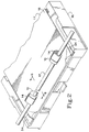
- FIG. 2 is a perspective view showing a pick engager according to the present invention in position for picking a sheet from a paper stack in a tray.
- FIG. 3 shows a side cross-sectional view of a pick roller.
- FIG. 4 is a side cross-sectional view of the preferred embodiment of a pick engager according to the present invention.
- FIG. 5 is a side cross-sectional view of an alternative embodiment of a pick engager according to the present invention.
- FIGS. 6-9 are successive side cross-sectional views of a picking mechanism which demonstrate the method of the present invention.
- a pair of pick engagers 10 are shown at 10, each mounted on a shaft 12 adjacent to a pick roller 14 (FIG. 3).
- Shaft 12 in turn is mounted in a printer (not shown) transversely above a paper tray 16 containing a paper stack 18.
- shaft 12 has a flat portion 13 formed in its periphery, the significance of which will be further described below.
- Shaft 12 is rotated by known means in response to a signal to pick a sheet.
- pick engager 10 can be seen in side cross-section to include a base portion 20 having an aperture 22 formed therein, and having a cam 23 formed on its outer peripheral surface.
- Aperture 22 is sized to closely receive shaft 12 for mounting pick engager 10 thereon, and includes first and second flat surfaces 24 and 25 which meet to form a fulcrum 26.
- the orientation of surfaces 24 and 25 allows pick engager to be rocked back and forth about fulcrum 26 between first and second respective rotational positions on shaft 12 in response to forces exerted on pick engager 10 by shaft 12 and paper stack 18 during operation as will be further described below.
- Pick engager is preferably formed from Delrin-AF, a teflon® impregnated polymeric resin manufactured by E. I. DuPont de Nemours and Co.. It will be appreciated that other materials having suitable strength and suitably low friction coefficients to ensure proper operation as described below may be substituted.
- Each pick roller 14 may be described as having a sector-like shape when viewed from the side as shown in FIG. 3.
- Aperture 28 is provided for mounting the pick roller in a fixed rotational position on shaft 12. Note that aperture 28 does not include a fulcrum such as the one provided in aperture 22 through pick engager 10, and pick roller 14 is therefore maintained in a fixed rotational position on shaft 12.
- Pick roller 14 includes a toothed surface 30 for frictionally engaging the top sheet of the paper stack when the pick roller is rotated by shaft 12.
- Pick roller is preferably made of a rubber such as EPDM, which is preferred for its combination of toughness, resilience and flexibility which allows toothed surface 30 to deform slightly as it engages the top sheet of the stack.
- FIGS. 6-9 where pick roller 14 (in phantom) and pick engager 10 are shown in cross-section mounted next to one another on shaft 12. Note that cam 23 of pick engager 10 extends beyond toothed surface 30 of pick roller 14.
- stack 18 Prior to being engaged by pick engager 10, stack 18 is biased upwardly within its tray (not shown) to a first position where the top sheet of the stack is urged against the underside of retaining lips 34 (FIG. 2) by a spring mechanism within the tray (not shown), one or more operative designs for which are known to those skilled in the art.
- shaft 12 Prior to beginning a picking cycle, shaft 12 is positioned so that pick roller 14 and pick engager 10 are disengaged from the stack 18 as shown in FIG. 6.
- pick engager 10 is in what shall be referred to as its rearward position on shaft 12, that is, with surface 24 in contact with flat 13 of shaft 12.
- shaft 12 Upon initiation of a picking cycle by the printer, shaft 12 is rotated forward, or clockwise.
- the cam 23 of pick engager 10 engages stack 18 ahead of pick roller 14 (FIG. 7), and the teflon-impregnated peripheral surface 23 of the pick engager slides across the top of stack 18 while the top sheet remains in place atop the stack.
- a roller 27 is incorporated in cam 23 to provide for rolling engagement of stack 18 instead of the sliding engagement provided by the preferred embodiment.
- stack 18 As shaft 12 continues to rotate, stack 18 is displaced downwardly within the tray by pick engager 10 (FIG. 8). This action of pick engager 10 serves two purposes. First, stack 18 is displaced downwardly to prevent premature engagement of pick roller 14 with the stack.
- multiple picking is avoided by ensuring that the upper sheets of the stack, and their corners in particular, remain beneath retaining lips 34 until the sheet is intended to be picked.
- the unintended picking of multiple sheets can be caused by sheets underlying the top sheet being partially dragged from the tray as a result of the frictional drag exerted on them by the top sheet as it is picked.
- Multiple picks are more likely to occur when the corners of one or more upper sheets in the stack have been pulled out from beneath retaining lips 34 by prior picks.
- the downward stack displacing action of pick engager 10 serves to return any such exposed corners to their position beneath retaining lips, reducing the chances that a multiple pick will occur.
- Peripheral surface 23 and fulcrum 26 are position relative to one another so that as pick engager is thus rotated to its forward position, peripheral surface 23 disengages from stack 18.
- stack 18 then is then urged upwardly into engagement with pick roller 14 by the spring mechanism in the tray containing stack 18.
- Shaft 12 is rotated further, and the top sheet of stack 18 is frictionally engaged and transported from atop the stack by toothed surface 30 of pick roller 14, and is transported into position for being printed upon by other mechanisms incorporated the printer and known to those skilled in the art.
- the timing of the release of stack 18 into engagement with pick roller 14 can be controlled much more closely than has heretofore been possible. Closer control of the timing of the engagement of pick roller 14 provides a corresponding reduction in top of sheet variation and skewing during picking. In addition, the occurrence of multiple picks is greatly reduced. All of these advantages together result in enhanced printer reliability, and are achieved with the addition of a minimum number of inexpensive components requiring little if any redesign of existing printers. In many cases, a pick engager according to the present invention may be incorporated into existing printer designs without any modification of existing components.
Landscapes
- Engineering & Computer Science (AREA)
- Mechanical Engineering (AREA)
- Sheets, Magazines, And Separation Thereof (AREA)
Abstract
Description
- The present invention relates generally to printers such as those used in conjunction with desk top computers for example, and in particular to an apparatus and method for reliably picking a sheet from a paper stack to feeding it to a position for being printed upon by the printer.
- Printers designed for use with word processors or general purpose computers must be capable of printing on various sizes of paper. Accordingly, printers are often designed to receive sheets of paper from one of a number of interchangeable, removable paper trays, each of which is sized to hold a particular size of paper. It naturally follows that the printer must include a mechanism for removing a sheet of paper from atop a stack held in the tray and for transporting the sheet to the required position for being printed upon. As is common among those skilled in the art, this process is referred to hereinafter as picking a sheet from the stack.
- In order for the printer to accurately print text or images in the desired location on a sheet, the sheet must be accurately and consistently positioned relative to the print head. Stated another way, the picking process must be highly accurate and reproducible by delivering the sheet to exactly the same position and in the proper orientation each time. In order to do so, the sheet must be picked from the stack in a highly predictable and consistent manner. Picking mechanisms typically include a rotatable drive shaft positioned above the stack and transversely to the direction of paper travel. Two pick rollers are mounted on the drive shaft for engaging the top sheet near each longitudinal side. A pick roller is usually made from a material such as soft plastic or rubber, and includes a cam like raised surface for frictionally engaging and advancing the top sheet as the drive shaft is rotated.
- Variability in the picking process takes two principal forms, top of sheet variation and skewing, each of which may arise in several ways. Top of sheet variation refers to variation in the distance a sheet is transported during picking, resulting in variation of the position of the top of the sheet relative to the printing head. Top of sheet variation may result from inconsistent engagement of the pick roller with the top sheet owing to relatively wide manufacturing tolerances or deflection of the relatively soft materials of construction. Alternatively, as shown in FIG. 1, top of sheet variability "d" may result from the change in position and/or orientation of the stack in the tray may vary as the stack is depleted, resulting in variation in the timing of engagement of the picking mechanism.
- Skewing refers to the sheet being rotated during picking, and usually results from variations in the timing of engagement between the pick rollers. Tighter control of manufacturing tolerances of pick rollers reduces skewing, but cannot eliminate it entirely due to the flexible nature of the materials of construction. Skewing may be reduced in cases where the stack is supported in the tray with one end raised by a process known as gravity dancing. The top sheet of the stack is engaged at its lower end by the pick rollers and fed along a downwardly angled path and engaged by the rotating dry rollers. The dry rollers are then rotated in reverse, moving the sheet upwardly until the sheet is clear of the dry rollers. As the dry rollers continue to rotate in reverse, the sheet is straightened relative to the dry rollers by being momentarily supported against the force of gravity with its lower edge positioned at the point where the dry rollers contact an underlying platten. The dry rollers are then rotated in the forward direction, advancing the paper to the printing position. While effective, this method requires an upwardly angled paper tray, and a relatively complex picking control algorithm.
- An additional problem encountered in picking is multiple picks, that is the picking of sheets underlying the top sheet. Multiple picks may occur when underlying sheets in the stack are partially "dragged" out of the tray by the picking of sheets above, and is not suitably remedied by known picking mechanisms.
- A need therefore exists for an improved picking mechanism which serves to accurately and consistently position successive sheets picked from atop a paper stack for printing, and which can be economically incorporated into known printer designs.
- The present invention is embodied in a pick engager for timing the engagement of a rotatable pick roller against a paper stack for picking the top sheet therefrom where the paper stack is biased towards the pick roller to a first position whereat the top sheet is frictionally engageable with the pick roller when the pick roller is rotated to a predetermined rotational position. The pick engager may comprise a body having a raised surface or a cam, and means connected to the body for rotating the pick engager for engaging the cam against the paper stack for urging the paper stack to a second position away from the pick roller until the pick roller reaches its predetermined rotational position. The means for rotating the pick engager may be a rotatable drive shaft on which the pick engager is mounted.
- The body of the pick engager may have a transverse aperture for receiving the drive shaft, and may further have a raised peripheral portion, or cam, for urging the paper stack to a second position spaced apart from the pick roller when the pick engager is rotated by the drive shaft. The pick engager may be rotatable about the drive shaft from a first rotational position to a second rotational position relative to the drive shaft for releasing the paper stack to its first biased position for engaging the top sheet with the pick roller when the pick engager is rotated to a predetermined position. The pick engager may be rotated to its second rotational position by a force exerted on the pick engager by the paper stack. The raised peripheral portion of the pick engager may alternatively include a roller for rollingly engaging the paper stack when the pick engager is rotated by the drive shaft.
- The present invention may also be embodied in an apparatus for picking a top sheet from atop a paper stack comprising a rotatable drive shaft, a pick roller drivably connected to the drive shaft and having a peripheral surface for frictionally engaging the stack for picking the top sheet therefrom when rotated by the drive shaft, urging means such as a spring for biasing the paper stack toward a first position where the top sheet is frictionally engageable with the pick roller when the pick roller is rotated, and one or more pick engagers as described above drivably connected to the drive shaft.
- The present invention may further be embodied in a printer comprising means for forming an image on a sheet, such as a printer head, means such as a tray for supporting a paper stack, and means for picking a first sheet from the stack, such as the apparatus for picking a top sheet from atop a paper stack just described.
- The present invention is embodied in a method of picking a sheet of paper from a paper stack, whatever the apparatus employed, comprising the steps of biasing the paper stack towards a rotatable pick roller to a first position where a first sheet of the paper stack is frictionally engageable by the pick roller, urging the paper stack to a second position spaced apart from said pick roller, rotating said pick roller to said predetermined rotational position, and releasing said paper stack to said biased first position for frictionally engaging said top sheet with said pick roller for picking said top sheet from the stack. The steps of urging the paper stack to its second position and releasing said paper stack to its biased first position may comprise the steps of providing a rotatable drive shaft having one or more pick engagers mounted thereon as described above.
- The step of releasing said paper stack to its biased first position may include the steps of rotating the drive shaft and engaging the raised peripheral surface of the pick engager against the paper stack and urging the paper stack to its second position, rotating the pick roller to the predetermined picking position, and rotating the pick engager about the drive shaft to its second rotational position for disengaging the raised peripheral surface from the paper stack, thereby releasing the paper stack to its first biased position and engaging the pick roller with the top sheet of the paper stack. The step of rotating the pick engager about the drive shaft to its second rotational position may include urging the paper stack against the pick engager to exert a rotating force thereon.
- The apparatus and method of the present invention will now be described in greater detail with reference to the figures.
- FIG. 1 is a schematic side view of a prior art picking mechanism showing top of sheet variability with varying stack height.
- FIG. 2 is a perspective view showing a pick engager according to the present invention in position for picking a sheet from a paper stack in a tray.
- FIG. 3 shows a side cross-sectional view of a pick roller.
- FIG. 4 is a side cross-sectional view of the preferred embodiment of a pick engager according to the present invention.
- FIG. 5 is a side cross-sectional view of an alternative embodiment of a pick engager according to the present invention.
- FIGS. 6-9 are successive side cross-sectional views of a picking mechanism which demonstrate the method of the present invention.
- Referring to FIGS. 2 - 5, a pair of
pick engagers 10 according to the present invention are shown at 10, each mounted on ashaft 12 adjacent to a pick roller 14 (FIG. 3).Shaft 12 in turn is mounted in a printer (not shown) transversely above apaper tray 16 containing apaper stack 18. As best seen by reference to FIG. 6,shaft 12 has aflat portion 13 formed in its periphery, the significance of which will be further described below.Shaft 12 is rotated by known means in response to a signal to pick a sheet. - Turning to FIG. 4, pick engager 10 can be seen in side cross-section to include a
base portion 20 having anaperture 22 formed therein, and having acam 23 formed on its outer peripheral surface.Aperture 22 is sized to closely receiveshaft 12 for mounting pick engager 10 thereon, and includes first and secondflat surfaces fulcrum 26. The orientation ofsurfaces fulcrum 26 between first and second respective rotational positions onshaft 12 in response to forces exerted on pick engager 10 byshaft 12 andpaper stack 18 during operation as will be further described below. Pick engager is preferably formed from Delrin-AF, a teflon® impregnated polymeric resin manufactured by E. I. DuPont de Nemours and Co.. It will be appreciated that other materials having suitable strength and suitably low friction coefficients to ensure proper operation as described below may be substituted. - Each
pick roller 14 may be described as having a sector-like shape when viewed from the side as shown in FIG. 3.Aperture 28 is provided for mounting the pick roller in a fixed rotational position onshaft 12. Note thataperture 28 does not include a fulcrum such as the one provided inaperture 22 throughpick engager 10, and pickroller 14 is therefore maintained in a fixed rotational position onshaft 12.Pick roller 14 includes atoothed surface 30 for frictionally engaging the top sheet of the paper stack when the pick roller is rotated byshaft 12. Pick roller is preferably made of a rubber such as EPDM, which is preferred for its combination of toughness, resilience and flexibility which allowstoothed surface 30 to deform slightly as it engages the top sheet of the stack. - The method and operation of the apparatus of the present invention are best described by reference to FIGS. 6-9, where pick roller 14 (in phantom) and pick
engager 10 are shown in cross-section mounted next to one another onshaft 12. Note thatcam 23 ofpick engager 10 extends beyondtoothed surface 30 ofpick roller 14. Prior to being engaged bypick engager 10,stack 18 is biased upwardly within its tray (not shown) to a first position where the top sheet of the stack is urged against the underside of retaining lips 34 (FIG. 2) by a spring mechanism within the tray (not shown), one or more operative designs for which are known to those skilled in the art. Prior to beginning a picking cycle,shaft 12 is positioned so thatpick roller 14 and pickengager 10 are disengaged from thestack 18 as shown in FIG. 6. Moreover, pickengager 10 is in what shall be referred to as its rearward position onshaft 12, that is, withsurface 24 in contact with flat 13 ofshaft 12. - Upon initiation of a picking cycle by the printer,
shaft 12 is rotated forward, or clockwise. Thecam 23 ofpick engager 10 engagesstack 18 ahead of pick roller 14 (FIG. 7), and the teflon-impregnatedperipheral surface 23 of the pick engager slides across the top ofstack 18 while the top sheet remains in place atop the stack. In an alternative embodiment shown in FIG. 5, aroller 27 is incorporated incam 23 to provide for rolling engagement ofstack 18 instead of the sliding engagement provided by the preferred embodiment. Asshaft 12 continues to rotate, stack 18 is displaced downwardly within the tray by pick engager 10 (FIG. 8). This action ofpick engager 10 serves two purposes. First, stack 18 is displaced downwardly to prevent premature engagement ofpick roller 14 with the stack. Second, multiple picking is avoided by ensuring that the upper sheets of the stack, and their corners in particular, remain beneath retaininglips 34 until the sheet is intended to be picked. As mentioned above, the unintended picking of multiple sheets can be caused by sheets underlying the top sheet being partially dragged from the tray as a result of the frictional drag exerted on them by the top sheet as it is picked. Multiple picks are more likely to occur when the corners of one or more upper sheets in the stack have been pulled out from beneath retaininglips 34 by prior picks. The downward stack displacing action ofpick engager 10 serves to return any such exposed corners to their position beneath retaining lips, reducing the chances that a multiple pick will occur. - As
shaft 12 is rotated and pickengager 10 is bearing on and downwardly displacingstack 18, the stack is exerting an equal reaction force upwardly onpick engager 10 through the point of contact 36 withcam 23 according to well-known physical principals. During the portion of the picking cycle when the point of contact is to the right offulcrum 26 as viewed in FIGS. 5 and 6, the reaction force exerted by the stack is manifest as a counterclockwisetorque holding surface 24 firmly against flat 13 and pickengager 10 in its rearward position onshaft 12. Asshaft 12 is turned farther, however, the point of contact 36 moves to the left offulcrum 26, and the torque onpick engager 10 is reversed, causingpick engager 10 to rotate clockwise aboutshaft 12 to its forward position withsurface 25 against flat 13.Peripheral surface 23 andfulcrum 26 are position relative to one another so that as pick engager is thus rotated to its forward position,peripheral surface 23 disengages fromstack 18. stack 18 then is then urged upwardly into engagement withpick roller 14 by the spring mechanism in thetray containing stack 18.Shaft 12 is rotated further, and the top sheet ofstack 18 is frictionally engaged and transported from atop the stack bytoothed surface 30 ofpick roller 14, and is transported into position for being printed upon by other mechanisms incorporated the printer and known to those skilled in the art. - Owing to the close manufacturing tolerances which can be achieved with the material from which pick
engager 10 is made, and its rigidity under the reaction force exerted bystack 12, the timing of the release ofstack 18 into engagement withpick roller 14 can be controlled much more closely than has heretofore been possible. Closer control of the timing of the engagement ofpick roller 14 provides a corresponding reduction in top of sheet variation and skewing during picking. In addition, the occurrence of multiple picks is greatly reduced. All of these advantages together result in enhanced printer reliability, and are achieved with the addition of a minimum number of inexpensive components requiring little if any redesign of existing printers. In many cases, a pick engager according to the present invention may be incorporated into existing printer designs without any modification of existing components. - While the present invention has been described with reference to the preferred embodiment, it will be appreciated that numerous modifications are possible without departing from the scope of the following claims.
Claims (10)
- A pick engager 10 for timing the engagement of a rotatable pick roller 14 against a stack of sheets 17 for picking the top sheet 18 therefrom, the stack 17 being biased towards the pick roller 14 to a first position whereat the top sheet 18 is frictionally engageable with the pick roller 14 when the pick roller 14 is rotated to a predetermined rotational position, the pick engager 10 comprising:
a rotatable body 20 having a raised peripheral surface 23 for engaging the stack 17 and urging the stack 17 to a second position spaced apart from the pick roller 14 when said pick engager 10 is rotated;
drive means drivably connected to said body 20 for rotating said pick engager 10; and
means for releasing said stack 17 to its first biased position when the pick roller 14 reaches said predetermined rotational position. - A pick engager 10 according to claim 1 wherein said pick engager drive means comprises a rotatable drive shaft 12, and further comprises a transverse aperture 22 formed in said body 20 for drivably receiving the rotatable drive shaft 12, and wherein said means for releasing said stack 17 to its first biased position includes said pick engager 10 being reversibly rotatable about said drive shaft 12 from a first rotational position to a second rotational position relative to said drive shaft 12 when the pick engager 10 is rotated to a predetermined position.
- A pick engager 10 according to claim 2 wherein said drive shaft 12 has a flat circumferential surface 13 formed thereon, and wherein said transverse body aperture 22 has a first flat surface 24 for engaging said flat circumferential drive shaft surface 13 when said pick engager 10 is in its first rotational position on said drive shaft 12, and has a second flat surface 26 for engaging said flat circumferential drive shaft surface 13 when said pick engager 10 is in its second rotational position on said drive shaft 12.
- The pick engager of claim 2 wherein said pick engager 10 is rotatable to said second rotational position relative to the drive shaft 12 in response to a force exerted on said pick engager 10 by the stack 17.
- The pick engager of claim 1 wherein said raised peripheral portion includes a roller 27 for rollingly engaging the stack 17 when said pick engager 10 is rotated by the drive shaft 12.
- A printer comprising:
means for forming an image on a sheet 18;
means for supporting a stack of sheets 17;
means for picking a top sheet 18 from the stack 17, said picking means including:
a rotatable drive shaft 12;
a pick roller 14 drivably connected to said drive shaft 12 and having a peripheral surface 30 for frictionally engaging and transporting the top sheet 18 from atop the stack 17 when rotated by said drive shaft 12;
urging means for biasing the stack 17 toward a first position whereat the first sheet 18 is frictionally engageable with the pick roller 14 when the pick roller 14 is rotated;
a pick engager 10 drivably connected to said drive shaft 12, said pick engager 10 including a body 20 having a transverse aperture 22 for drivably receiving the rotatable drive shaft 12, and further including a raised peripheral portion 23 for urging the stack 17 to a second position spaced apart from the pick roller 14 when said pick engager 10 is rotated by the drive shaft 12; and
said pick engager 10 being rotatable about the drive shaft 12 from a first rotational position to a second rotational position relative to the drive shaft 12 for releasing said stack 17 to its first biased position for engaging the top sheet 18 against the pick roller 14 when the drive shaft 12 is rotated to a predetermined position. - A method of picking a sheet of paper from a stack of sheets comprising the steps of:
biasing the stack 17 towards a rotatable pick roller 14 toward a first position whereat a top sheet 18 of the stack 17 is frictionally engageable by said pick roller 14;
urging the stack 17 to a second position spaced apart from said pick roller 14;
rotating said pick roller 14 to said predetermined rotational position; and
releasing said stack 17 to said first biased position for frictionally engaging said top sheet 18 with said pick roller 14 for picking said top sheet 18 from the stack 17. - The method of claim 7 wherein the steps of urging the stack to said second position and releasing said stack to said first biased position comprise:
providing a rotatable drive shaft 12 having a pick engager 10 mounted thereon, said pick engager 10 having a body 20 including a transverse aperture 22 therethrough for drivably receiving said drive shaft 12, and having a raised peripheral portion 23 for urging the stack 17 to a second position spaced apart from said pick roller 14 when said pick engager 10 is rotated; and
said pick engager 10 being rotatable about the drive shaft 12 from a first rotational position to a second rotational position relative to the drive shaft 12 for releasing said stack 17 to its first biased position for engaging the top sheet 18 with the pick roller 14 when the drive shaft 12 is rotated to a predetermined position. - The method of claim 8 wherein the step of releasing said stack to said first biased position includes the steps of:
rotating the drive shaft 12, thereby engaging the raised peripheral surface 23 of said pick engager 10 against the stack 17 and urging the stack 17 to its second position;
rotating the pick roller 14 to said predetermined picking position; and
rotating said pick engager 10 about the drive shaft 12 to said second rotational position for disengaging the raised peripheral surface 23 from the stack 17, thereby releasing the stack 17 to its first biased position and engaging the pick roller 14 with the top sheet 18 of the stack 17. - The method of claim 9 wherein the step of rotating said pick engager 10 about the drive shaft 12 to said second rotational position includes urging the stack 17 against said pick engager 10 to exert a rotating force thereon.
Applications Claiming Priority (2)
| Application Number | Priority Date | Filing Date | Title |
|---|---|---|---|
| US07/967,079 US5326184A (en) | 1992-10-26 | 1992-10-26 | Apparatus and method for picking paper from a stack |
| US967079 | 1992-10-26 |
Publications (3)
| Publication Number | Publication Date |
|---|---|
| EP0595524A2 true EP0595524A2 (en) | 1994-05-04 |
| EP0595524A3 EP0595524A3 (en) | 1994-08-31 |
| EP0595524B1 EP0595524B1 (en) | 1996-12-27 |
Family
ID=25512268
Family Applications (1)
| Application Number | Title | Priority Date | Filing Date |
|---|---|---|---|
| EP93308286A Expired - Lifetime EP0595524B1 (en) | 1992-10-26 | 1993-10-18 | An apparatus and method for picking paper from a stack |
Country Status (4)
| Country | Link |
|---|---|
| US (1) | US5326184A (en) |
| EP (1) | EP0595524B1 (en) |
| JP (1) | JP3468559B2 (en) |
| DE (1) | DE69306913T2 (en) |
Cited By (2)
| Publication number | Priority date | Publication date | Assignee | Title |
|---|---|---|---|---|
| EP0681973A1 (en) * | 1994-05-11 | 1995-11-15 | Hewlett-Packard Company | Pre-pick device for hard copy media pick mechanism |
| GB2349872A (en) * | 1999-05-11 | 2000-11-15 | Mars Inc | Buckling sheet separator |
Families Citing this family (11)
| Publication number | Priority date | Publication date | Assignee | Title |
|---|---|---|---|---|
| JP3098369B2 (en) * | 1993-12-15 | 2000-10-16 | キヤノン株式会社 | Sheet feeding device and recording device |
| US5630583A (en) * | 1995-12-22 | 1997-05-20 | Hewlett-Packard Company | Sheet media feeding mechanism having a variable radius feed roller |
| KR0165339B1 (en) * | 1995-12-30 | 1999-05-01 | 김광호 | A printer |
| US6076821A (en) * | 1998-09-14 | 2000-06-20 | Lexmark International, Inc. | Method and apparatus for feeding sheets |
| US6519443B1 (en) | 2001-10-02 | 2003-02-11 | Lexmark International, Inc. | Method for calculating a print medium pick time for an imaging apparatus that transports print media at variable speeds |
| KR100561441B1 (en) * | 2004-08-09 | 2006-03-17 | 삼성전자주식회사 | Paper pickup device and image forming device having same |
| KR100594807B1 (en) * | 2004-09-06 | 2006-07-03 | 삼성전자주식회사 | Paper pickup unit and image forming apparatus having same |
| KR100692573B1 (en) * | 2005-08-31 | 2007-03-13 | 삼성전자주식회사 | Paper feeder of image forming machine |
| JP4872772B2 (en) * | 2007-04-12 | 2012-02-08 | コニカミノルタビジネステクノロジーズ株式会社 | Paper feeder |
| DE102008018935A1 (en) * | 2008-04-15 | 2009-10-22 | Wincor Nixdorf International Gmbh | Single-sheet handling device for inputting and outputting rectangular individual sheets, in particular banknotes, into or out of a container |
| JP2010023956A (en) * | 2008-07-16 | 2010-02-04 | Sharp Corp | Paper feed apparatus |
Family Cites Families (6)
| Publication number | Priority date | Publication date | Assignee | Title |
|---|---|---|---|---|
| BE790506A (en) * | 1971-10-30 | 1973-04-25 | Agfa Gevaert Nv | SEPARATOR DEVICE PARTICULARLY FOR ELECTROSTATIC COPIER |
| JPS5523352U (en) * | 1978-08-02 | 1980-02-15 | ||
| JPS5942867B2 (en) * | 1978-08-29 | 1984-10-18 | キヤノン株式会社 | Sheet feeding device |
| US5019839A (en) * | 1986-12-25 | 1991-05-28 | Canon Kabushiki Kaisha | Recording apparatus having a movable sheet guide member |
| JP2998222B2 (en) * | 1991-02-12 | 2000-01-11 | ブラザー工業株式会社 | Paper feeder |
| US5149077A (en) * | 1991-06-24 | 1992-09-22 | Xerox Corporation | Hybrid nudger roll |
-
1992
- 1992-10-26 US US07/967,079 patent/US5326184A/en not_active Expired - Lifetime
-
1993
- 1993-10-18 DE DE69306913T patent/DE69306913T2/en not_active Expired - Fee Related
- 1993-10-18 EP EP93308286A patent/EP0595524B1/en not_active Expired - Lifetime
- 1993-10-26 JP JP28996593A patent/JP3468559B2/en not_active Expired - Fee Related
Cited By (4)
| Publication number | Priority date | Publication date | Assignee | Title |
|---|---|---|---|---|
| EP0681973A1 (en) * | 1994-05-11 | 1995-11-15 | Hewlett-Packard Company | Pre-pick device for hard copy media pick mechanism |
| GB2349872A (en) * | 1999-05-11 | 2000-11-15 | Mars Inc | Buckling sheet separator |
| GB2349872B (en) * | 1999-05-11 | 2004-01-14 | Mars Inc | Flexible media dispenser |
| US6715750B1 (en) | 1999-05-11 | 2004-04-06 | Mars Incorporated | Flexible media dispenser |
Also Published As
| Publication number | Publication date |
|---|---|
| EP0595524B1 (en) | 1996-12-27 |
| JP3468559B2 (en) | 2003-11-17 |
| US5326184A (en) | 1994-07-05 |
| DE69306913D1 (en) | 1997-02-06 |
| EP0595524A3 (en) | 1994-08-31 |
| JPH06211366A (en) | 1994-08-02 |
| DE69306913T2 (en) | 1997-05-07 |
Similar Documents
| Publication | Publication Date | Title |
|---|---|---|
| KR100530582B1 (en) | Sheet separator | |
| KR100503595B1 (en) | Sheet aligning apparatus | |
| US5326184A (en) | Apparatus and method for picking paper from a stack | |
| US7891659B2 (en) | Paper feeding device, recording apparatus and information processing apparatus having the same | |
| KR100461589B1 (en) | Paper separating guide of a feeding cassette for printing apparatus | |
| US20020060396A1 (en) | Paper sheet feeding apparatus | |
| US4982942A (en) | Sheet feed mechanism | |
| US5779234A (en) | Printer sheet discharge method | |
| JPH06298380A (en) | Cassette paper feeder | |
| EP1557385B1 (en) | Automatic paper feed apparatus | |
| US7478805B2 (en) | Device for paper separating and guiding | |
| JP3192932B2 (en) | Printer paper feeder | |
| JP2801438B2 (en) | Automatic paper feeder and recording device | |
| JP3305146B2 (en) | Sheet material feeding device, recording device, and sheet material separating method | |
| EP0138065A1 (en) | Paper sheet feeder | |
| JP3756027B2 (en) | Printer paper feed mechanism | |
| JPH10258946A (en) | Paper feeder and printing method using the same | |
| JP3617174B2 (en) | Paper feeding device and printing device using the same | |
| JP2002037478A (en) | Paper feeder and image forming apparatus having the same | |
| KR101075951B1 (en) | Automatic paper feed apparatus | |
| JP3715814B2 (en) | Automatic paper feeder | |
| JP3646397B2 (en) | Paper feeding device and printing device using the same | |
| JP3648832B2 (en) | Paper feeding device and printing device using the same | |
| JPH06115748A (en) | Automatic paper feeder | |
| JPH0238235A (en) | Paper feeding device |
Legal Events
| Date | Code | Title | Description |
|---|---|---|---|
| PUAI | Public reference made under article 153(3) epc to a published international application that has entered the european phase |
Free format text: ORIGINAL CODE: 0009012 |
|
| AK | Designated contracting states |
Kind code of ref document: A2 Designated state(s): DE FR GB IT |
|
| PUAL | Search report despatched |
Free format text: ORIGINAL CODE: 0009013 |
|
| AK | Designated contracting states |
Kind code of ref document: A3 Designated state(s): DE FR GB IT |
|
| 17P | Request for examination filed |
Effective date: 19950206 |
|
| 17Q | First examination report despatched |
Effective date: 19950405 |
|
| GRAG | Despatch of communication of intention to grant |
Free format text: ORIGINAL CODE: EPIDOS AGRA |
|
| GRAH | Despatch of communication of intention to grant a patent |
Free format text: ORIGINAL CODE: EPIDOS IGRA |
|
| GRAH | Despatch of communication of intention to grant a patent |
Free format text: ORIGINAL CODE: EPIDOS IGRA |
|
| GRAA | (expected) grant |
Free format text: ORIGINAL CODE: 0009210 |
|
| AK | Designated contracting states |
Kind code of ref document: B1 Designated state(s): DE FR GB IT |
|
| PG25 | Lapsed in a contracting state [announced via postgrant information from national office to epo] |
Ref country code: IT Free format text: LAPSE BECAUSE OF FAILURE TO SUBMIT A TRANSLATION OF THE DESCRIPTION OR TO PAY THE FEE WITHIN THE PRE;WARNING: LAPSES OF ITALIAN PATENTS WITH EFFECTIVE DATE BEFORE 2007 MAY HAVE OCCURRED AT ANY TIME BEFORE 2007. THE CORRECT EFFECTIVE DATE MAY BE DIFFERENT FROM THE ONE RECORDED.SCRIBED TIME-LIMIT Effective date: 19961227 Ref country code: FR Effective date: 19961227 |
|
| REF | Corresponds to: |
Ref document number: 69306913 Country of ref document: DE Date of ref document: 19970206 |
|
| EN | Fr: translation not filed | ||
| PLBE | No opposition filed within time limit |
Free format text: ORIGINAL CODE: 0009261 |
|
| 26N | No opposition filed | ||
| REG | Reference to a national code |
Ref country code: GB Ref legal event code: 732E |
|
| REG | Reference to a national code |
Ref country code: GB Ref legal event code: IF02 |
|
| PGFP | Annual fee paid to national office [announced via postgrant information from national office to epo] |
Ref country code: GB Payment date: 20070125 Year of fee payment: 14 |
|
| PGFP | Annual fee paid to national office [announced via postgrant information from national office to epo] |
Ref country code: DE Payment date: 20070228 Year of fee payment: 14 |
|
| GBPC | Gb: european patent ceased through non-payment of renewal fee |
Effective date: 20071018 |
|
| PG25 | Lapsed in a contracting state [announced via postgrant information from national office to epo] |
Ref country code: DE Free format text: LAPSE BECAUSE OF NON-PAYMENT OF DUE FEES Effective date: 20080501 |
|
| PG25 | Lapsed in a contracting state [announced via postgrant information from national office to epo] |
Ref country code: GB Free format text: LAPSE BECAUSE OF NON-PAYMENT OF DUE FEES Effective date: 20071018 |