EP0595562A1 - Méthode et appareil de codage et de décodage d'un signal d'image - Google Patents
Méthode et appareil de codage et de décodage d'un signal d'image Download PDFInfo
- Publication number
- EP0595562A1 EP0595562A1 EP93308439A EP93308439A EP0595562A1 EP 0595562 A1 EP0595562 A1 EP 0595562A1 EP 93308439 A EP93308439 A EP 93308439A EP 93308439 A EP93308439 A EP 93308439A EP 0595562 A1 EP0595562 A1 EP 0595562A1
- Authority
- EP
- European Patent Office
- Prior art keywords
- quantization
- information
- picture
- linear
- picture signal
- Prior art date
- Legal status (The legal status is an assumption and is not a legal conclusion. Google has not performed a legal analysis and makes no representation as to the accuracy of the status listed.)
- Granted
Links
Images


Classifications
-
- H—ELECTRICITY
- H04—ELECTRIC COMMUNICATION TECHNIQUE
- H04N—PICTORIAL COMMUNICATION, e.g. TELEVISION
- H04N19/00—Methods or arrangements for coding, decoding, compressing or decompressing digital video signals
- H04N19/50—Methods or arrangements for coding, decoding, compressing or decompressing digital video signals using predictive coding
- H04N19/503—Methods or arrangements for coding, decoding, compressing or decompressing digital video signals using predictive coding involving temporal prediction
- H04N19/51—Motion estimation or motion compensation
- H04N19/577—Motion compensation with bidirectional frame interpolation, i.e. using B-pictures
-
- H—ELECTRICITY
- H04—ELECTRIC COMMUNICATION TECHNIQUE
- H04N—PICTORIAL COMMUNICATION, e.g. TELEVISION
- H04N19/00—Methods or arrangements for coding, decoding, compressing or decompressing digital video signals
- H04N19/10—Methods or arrangements for coding, decoding, compressing or decompressing digital video signals using adaptive coding
- H04N19/102—Methods or arrangements for coding, decoding, compressing or decompressing digital video signals using adaptive coding characterised by the element, parameter or selection affected or controlled by the adaptive coding
- H04N19/103—Selection of coding mode or of prediction mode
- H04N19/112—Selection of coding mode or of prediction mode according to a given display mode, e.g. for interlaced or progressive display mode
-
- H—ELECTRICITY
- H04—ELECTRIC COMMUNICATION TECHNIQUE
- H04N—PICTORIAL COMMUNICATION, e.g. TELEVISION
- H04N19/00—Methods or arrangements for coding, decoding, compressing or decompressing digital video signals
- H04N19/10—Methods or arrangements for coding, decoding, compressing or decompressing digital video signals using adaptive coding
- H04N19/102—Methods or arrangements for coding, decoding, compressing or decompressing digital video signals using adaptive coding characterised by the element, parameter or selection affected or controlled by the adaptive coding
- H04N19/124—Quantisation
- H04N19/126—Details of normalisation or weighting functions, e.g. normalisation matrices or variable uniform quantisers
-
- H—ELECTRICITY
- H04—ELECTRIC COMMUNICATION TECHNIQUE
- H04N—PICTORIAL COMMUNICATION, e.g. TELEVISION
- H04N19/00—Methods or arrangements for coding, decoding, compressing or decompressing digital video signals
- H04N19/60—Methods or arrangements for coding, decoding, compressing or decompressing digital video signals using transform coding
- H04N19/61—Methods or arrangements for coding, decoding, compressing or decompressing digital video signals using transform coding in combination with predictive coding
-
- H—ELECTRICITY
- H04—ELECTRIC COMMUNICATION TECHNIQUE
- H04N—PICTORIAL COMMUNICATION, e.g. TELEVISION
- H04N19/00—Methods or arrangements for coding, decoding, compressing or decompressing digital video signals
- H04N19/85—Methods or arrangements for coding, decoding, compressing or decompressing digital video signals using pre-processing or post-processing specially adapted for video compression
-
- H—ELECTRICITY
- H04—ELECTRIC COMMUNICATION TECHNIQUE
- H04N—PICTORIAL COMMUNICATION, e.g. TELEVISION
- H04N19/00—Methods or arrangements for coding, decoding, compressing or decompressing digital video signals
- H04N19/10—Methods or arrangements for coding, decoding, compressing or decompressing digital video signals using adaptive coding
- H04N19/102—Methods or arrangements for coding, decoding, compressing or decompressing digital video signals using adaptive coding characterised by the element, parameter or selection affected or controlled by the adaptive coding
- H04N19/124—Quantisation
-
- H—ELECTRICITY
- H04—ELECTRIC COMMUNICATION TECHNIQUE
- H04N—PICTORIAL COMMUNICATION, e.g. TELEVISION
- H04N19/00—Methods or arrangements for coding, decoding, compressing or decompressing digital video signals
- H04N19/10—Methods or arrangements for coding, decoding, compressing or decompressing digital video signals using adaptive coding
- H04N19/102—Methods or arrangements for coding, decoding, compressing or decompressing digital video signals using adaptive coding characterised by the element, parameter or selection affected or controlled by the adaptive coding
- H04N19/13—Adaptive entropy coding, e.g. adaptive variable length coding [AVLC] or context adaptive binary arithmetic coding [CABAC]
-
- H—ELECTRICITY
- H04—ELECTRIC COMMUNICATION TECHNIQUE
- H04N—PICTORIAL COMMUNICATION, e.g. TELEVISION
- H04N19/00—Methods or arrangements for coding, decoding, compressing or decompressing digital video signals
- H04N19/60—Methods or arrangements for coding, decoding, compressing or decompressing digital video signals using transform coding
-
- H—ELECTRICITY
- H04—ELECTRIC COMMUNICATION TECHNIQUE
- H04N—PICTORIAL COMMUNICATION, e.g. TELEVISION
- H04N19/00—Methods or arrangements for coding, decoding, compressing or decompressing digital video signals
- H04N19/90—Methods or arrangements for coding, decoding, compressing or decompressing digital video signals using coding techniques not provided for in groups H04N19/10-H04N19/85, e.g. fractals
- H04N19/91—Entropy coding, e.g. variable length coding [VLC] or arithmetic coding
Definitions
- This invention relates to a method for quantization and inverse quantization of picture data using a recording medium for storage, such as an optical disc or a magnetic tape, an apparatus for recording/reproducing the information using the recording medium for storage, such as an optical disc or a magnetic tape, and an apparatus for transmitting/receiving the information which may be suitably applied to a so-called teleconferencing system, a moving-picture telephone system or a broadcasting system.
- a recording medium for storage such as an optical disc or a magnetic tape
- an apparatus for recording/reproducing the information using the recording medium for storage such as an optical disc or a magnetic tape
- an apparatus for transmitting/receiving the information which may be suitably applied to a so-called teleconferencing system, a moving-picture telephone system or a broadcasting system.
- the difference between picture frames of picture signals is taken for reducing the redundancy along the time scale by taking advantage of the correlation between frames, and subsequently the processing by discrete cosine transform (DCT) is performed for reducing the redundancy along the spatial scale by taking advantage of line correlation for achieving high efficiency encoding of the picture signals.
- DCT discrete cosine transform
- a picture PC12 may be generated by taking the difference between the picture signals of the frame pictures PC1 and PC2, as shown at (B) in Fig.9, while a picture PC23 may be generated by taking the difference between the picture signals of the frame pictures PC2 and PC3, as shown at (B) in Fig.9. Since the frame pictures temporally adjacent to each other usually are not changed significantly from each other, the difference between these two frame pictures is of a smaller value.
- difference signals representing the hatched portion of the picture PC12 shown at (B) in Fig.9 are produced as the difference between the picture signal of the frame pictures PC1 and PC2, shown at (A) in Fig.9, while difference signals representing the hatched portion of the picture PC23 shown at (B) in Fig.9 are produced as the difference between the picture signal of the frame pictures PC2 and PC3, shown at (A) in Fig.9.
- the encoding volume may be compressed by encoding these difference signals.
- the frame pictures are classed into intra-coded pictures or I-pictures, predictive-coded pictures or P-pictures and bidirectionally predictive-coded pictures or B-pictures.
- 17 frame picture signals of from a frame F1 to a frame F17 are grouped together as a group of pictures, which is a processing unit.
- the leading frame F1 is encoded as the I-picture
- the second frame F2 and the third frame F3 are processed as the B-picture and the P-picture, respectively.
- the fourth frames ff. that is the frames F4 up to F17, are processed alternately as the B-pictures and as the P-pictures.
- the one-frame picture signals are transmitted in their entirety.
- the picture signals for the B-picture a difference between means values of the picture signals of a temporally proceeding frame and means values of the picture signals of a temporally succeeding frame is found and encoded for transmission, as shown at (B) in Fig.10.
- Figs.11 (A) and (B) illustrate the principle of the method for encoding the moving picture signals as described above.
- Figs.11(A) and (B) illustrate frame data of the moving picture signals and the transmission frame data, respectively.
- this frame F1 is directly transmitted on the transmission channel as transmission data FIX (non-interpolated transmission data).
- the second frame F2 is processed a the B-picture, that is as an interpolated frame
- the difference between mean values of the temporally succeeding frame F3 (inter-frame encoded non-interpolated frame) and the temporally preceding frame F1 is taken and transmitted as the transmission data (interpolated transmission frame data).
- the B-picture is processed in four different modes.
- the first processing mode consists in directly transmitting the data of the original frame F2 as the transmission data F2X, as shown by a broken-line arrow SP1 (intra-coding).
- the processing mode is similar to that for the I-picture.
- the second processing mode consists in taking a difference between the frame F2 and the temporally succeeding frame F3 and transmitting the difference as indicated by a broken-line arrow SP2 in Fig.11 (backward predictive coding).
- the third processing mode consists in taking a difference between the frame F2 and the temporally preceding frame F1 and transmitting the difference as indicated by a broken-line arrow SP3 in Fig.11 (backward predictive coding).
- the fourth processing mode consists in taking a difference between the temporally preceding frame F1 and the temporally succeeding frame F3 and transmitting the difference as transmission data F2X as indicated by a broken-line arrow SP4 in Fig.11 (bidirectionally predictive coding).
- a motion vector x1 between the frame reference (frame under consideration) and a prediction picture (picture of the frame the difference from reference the frame of which is calculated), that is a motion vector x1 between the frames F1 and F2 for forward prediction coding, a motion vector x2, that is a motion vector between the frames F2 and F3 for backward prediction coding, or both the motion vectors x1 and x2 for bidirectionally predictive-coding, are transmitted along with the difference data.
- difference signals between the frame F3 and the temporally preceding frame F1 as the prediction picture as indicated by a broken-line arrow SP3 and a motion vector x3 are calculated and transmitted as transmission data F3X (forward prediction-coding).
- transmission data F3X forward prediction-coding
- data of the original frame F3 are directly transmitted as transmission data F3X, as indicated by a broken-line arrow SP1 (intra-coding).
- the frame F4 of the B-picture and the frame F5 of the B-picture are processed in the same manner as above for producing transmission data F4X, F5X and motion vectors x4, x5 and x6.
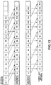
- Fig.12 illustrates another example of inter-frame encoding and intra-frame encoding of a picture sequence.
- a cycle of 15 frames represents an encoding unit.
- a frame 2 is an I-picture
- frames 5, 8, 11 and 14 are P-pictures coded by inter-frame coding, with the prediction being made only from the forward direction
- frames 0, 1, 3, 4, 6, 7, 9, 10, 12 and 13 are B-pictures coded by inter-frame coding, with prediction being made from both the backward and forward directions.
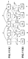
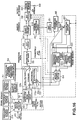
- Fig.14 illustrates an example of the construction of an apparatus for encoding, transmitting and decoding the moving picture signals based on the above-described principle.
- the encoding apparatus 1 encodes the input picture signals and transmits the encoded signals to a recording medium 3 for recording thereon.
- a decoding apparatus 2 reproduces, decodes and outputs signals recorded on the recording medium 3.
- video signals VD are entered via an input terminal 10 to a pre-processing circuit 11 and separated into luminance signals and color signals, herein chrominance difference signals.
- the luminance signals and the chrominance signals are separately analog-to-digital converted by analog-to-digital (A/D) converters 12, 13.
- A/D analog-to-digital
- the digitized picture signals from the A/D converters 12, 13 are transmitted to and stored in a frame memory 14.
- the luminance signals and the chrominance signals are stored in a luminance signal frame memory 15 and chrominance frame memory 16, respectively.
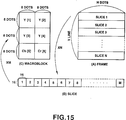
- a format converting circuit 17 translates frame format signals stored in the frame memory 14 into block format signals.
- the video signals stored in the frame memory 14 are frame format data consisting of V lines each consisting of H dots, as shown at (A) in Fig.15.
- the format converting circuit 17 divides the one-frame signals into N slices each consisting of 16 lines. Each slice is divided into M macroblocks, as shown at B in Fig.15. Each macroblock is made up of luminance signals corresponding to 16x16 pixels or dots, which are further divided into blocks Y[1] to Y[4], each consisting of 8x8 dots, as shown at (C) in Fig.15.
- the 16x16 dot luminance signals are associated with 8x8 dot Cb signals and 8x8 dot Cr signals.
- the moving picture signals within the slices shown at (A) in Fig.15 are arrayed so that moving picture signals represent continuous signals on the basis of the macroblocks shown at (C) in Fig.15 and the moving picture signals within each of the macroblocks also represent continuous block-based signals in the raster scanning sequence.
- the data thus converted into block format data are supplied from the format converting circuit 17 to an encoder 18 and encoded in a manner which will be explained in more detail by referring to Fig.16.
- the signals encoded by the encoder 18 are outputted as a bit stream to the transmission channel so as to be recorded on for example, the recording medium 3.
- the data reproduced from the recording medium 3 are supplied to a decoder 31 of the decoding device 2 so as to be decoded in a manner which will be explained in more detail by referring to Fig.19.
- the data decoded by the decoder 31 are entered to a format converting circuit 32 and thereby converted from the block format data into the above-mentioned frame format data.
- the luminance signals of the frame format are transmitted to and stored in a luminance signal frame memory 34 of a frame memory 33 and the chrominance signals are transmitted to and stored in a chrominance signal frame memory 35.
- the luminance signals and the color difference signals read out from the luminance signal frame memory 34 and from the chrominance signal frame memory 35 are digital-to-analog converted by the digital-to-analog converters (D/A converters) 36, 37.
- the resulting analog signals are transmitted to a post-processing circuit 38 so as to be synthesized into output picture signals which are outputted at an output terminal 30 for display on a display device, such as CRT.
- the picture data supplied via an input terminal 49 are entered on the macroblock basis to a motion vector detecting circuit 50 which is adapted for processing the picture data of the respective frames a the I-picture, P-pictures or B-pictures, in accordance with w pre-set sequence.
- the respective input frame pictures are processed as the I-picture, P-picture or as the B-picture in the pre-set manner.
- the group of pictures constituted by the frames F1 to F17 shown in Fig.10 is processed in the sequence of I, B, P, B, P, ⁇ B, P, as shown therein.
- the picture data of the frame to be processed as the I-picture is transmitted from the motion vector detection circuit 50 to a forward original picture section 51a of a frame memory 51 for storage therein, while the picture data of the frame to be processed as the B-picture, for example, the frame F2, is transmitted to and stored in a reference original picture section 51a of the frame memory 51 and the picture data of the frame to be processed as the P-picture, for example, the frame F3, is transmitted to and stored in a backward original picture section 51c of the frame memory 51.
- the picture data of the first P-picture, so far stored in the backward original picture section 51c, that is the frame F4 is transferred to the forward original picture section 51a, and the picture of the next B-picture, that is the frame F4, is stored (or overwritten) in the original picture section 51b, while the picture data of the next P-picture, that is the frame F5, is stored (or overwritten) in the backward original picture section 51c.
- the sequence of the operations is repeated sequentially.
- the signals of the respective pictures, stored in the frame memory 51, are read out and transmitted to a prediction mode changeover circuit 52 in which the frame prediction mode operation or the field prediction mode operation is carried out.
- a prediction mode changeover circuit 52 in which the frame prediction mode operation or the field prediction mode operation is carried out.
- the intra-coding, forward predictive coding, backward predictive coding or bidirectional predictive coding operations are carried out under control of a prediction decision circuit 54.
- the decision as to which of these operations is to be carried out is made depending on prediction error signals, that is the difference between the reference picture (picture under consideration), and the prediction picture therefor. Consequently, the motion vector detection circuit 50 generates the sum of absolute or squared values or of the prediction error signals employed for the decision.
- the frame prediction mode and the field prediction mode in the prediction mode switching circuit 52 is explained.
- the prediction mode switching circuit 52 directly outputs the four luminance blocks Y[1] to Y[4] supplied from the motion vector detection circuit 50 to a downstream side processing unit 53.
- the odd-field line data and the even-field line data co-exist in each luminance block.
- solid lines and broken lines in each macroblock represent odd-field line data (first field line data) and even-field line data (second field line data), respectively, while a and b represent units of the motion compensation.
- prediction is performed based on the four luminance blocks (macroblocks) and a motion vector is associated with the four luminance blocks.
- the signals entered in the array shown at (A) in Fig.17 from the motion vector detection circuit 50 are constructed so that the luminance blocks Y[1] and Y[2] are composed only of odd-field line data while the remaining two luminance blocks Y[3] and Y[4] are composed only of even-field line data, as shown at (B) in Fig.17.
- These luminance blocks Y[1] to Y[4] are outputted to the processing section 53.
- a motion vector is associated with the two luminance blocks Y[1] and Y[2], while another motion vector is associated with the other two luminance blocks Y[3] and Y[4].
- the motion vector detection circuit 50 outputs the sum of absolute values of the prediction errors for the frame prediction mode and the sum of absolute values of the prediction errors for the field prediction mode to the prediction mode changeover circuit 52.
- the changeover circuit 52 compares these sums of the absolute values of the prediction errors for the frame prediction mode and the field prediction mode to each other to cause the above-described operations for the prediction mode having the lesser value of the sum to be performed to output the resulting data to the processing section 53.
- the motion vector detection circuit 50 outputs the signals having the configuration for the selected mode to the prediction mode changeover circuit 52.
- the prediction mode changeover circuit 52 directly outputs the signals to the downstream processing section 53.
- the chrominance signals are supplied to the processing unit 53 in a state in which the odd-line field data co-exist with the even-line field data, as shown at (A) in Fig.17.
- the upper half (four lines) of the chrominance blocks Cb[5] and Cr[6] are the odd-field chrominance signals associated with the luminance blocks Y[1] and Y[2], respectively, while the lower half (four lines) of the chrominance blocks Cb[5] and Cr[6] are the even-field chrominance signals associated with the luminance blocks Y[3] and Y[4], respectively, as shown at (B) in Fig.17.
- the prediction decision circuit 54 selects the least one of the sums of the absolute values of the prediction errors of the forward predictive coding, backward predictive coding and the bidirectional predictive coding, as the sum of the absolute values of the prediction errors of the inter-prediction. Besides, the prediction decision circuit 54 selects, by comparison, the smaller one of the sum of the absolute values of the prediction errors for the inter-prediction and the sum of the absolute values of the prediction errors for the intra-coding and selects the mode corresponding to the selected sum of the absolute values as the prediction mode. That is, if the sum of the absolute values of the prediction errors for the intra-coding has the smaller value, the intra-picture prediction mode is set. If the sum of the absolute values of the prediction errors for the inter-coding has the smaller value, one of the forward predictive mode, the backward predictive mode and the bidirectional predictive mode having the smallest value is set.
- the motion vector detection circuit 50 supplies the signals of the macroblock of the reference picture to the processing section 53 via the prediction mode changeover circuit 52, in the configuration corresponding to the frame prediction mode or the field prediction mode as selected by the prediction mode changeover circuit 52 as shown in Fig.17. Besides, the motion vector detection circuit 50 detects the motion vector between the prediction picture and the reference picture associated with the prediction mode of the four prediction modes as selected by the prediction decision circuit 52 to output the detected motion vector to the variable length coding circuit 58 and the motion compensation circuit 64 as later explained. Meanwhile, the motion vector is selected which will give the smallest value of the sum of the absolute values of the corresponding prediction errors.
- the prediction decision circuit 54 sets the intra-frame (intra-picture) prediction mode, that is the mode in which the motion compensation is not carried out, as the predictive mode, and causes a switch of the processing section 53 be set to a fixed contact a .
- the picture data of the I-picture are entered to a DCT changeover circuit 55.
- the CDT mode changeover circuit 55 sets the data of the four luminance blocks to the state in which the odd-field line data co-exist with the even-field line data (frame DCT mode) or to the state in which the odd-field line data are separated from the even-field line data (field DCT mode), as shown at (A) or (B) in Fig.18, and outputs the data in one of these states to a DCT circuit 56. That is, the DCT mode changeover circuit 55 compares the coding efficiency which is achieved when the DCT operation is performed on the odd-field data coexisting with the even-field data to the coding efficiency which is achieved when the DCT operation is performed on the odd-field data and the even-field data separated from each other to select the mode having the higher coding efficiency.
- the input signals are set to a configuration in which the odd-field line data co-exist with the even-field line data, as shown at (A) in Fig.18.
- the differences between the odd-field line signals and the even-field line signals vertically adjacent to one another are calculated, and the sum of the absolute values or the squared values of the differences is found.
- the input signals are set to a configuration in which the odd-field line data are separated from the even-field line data, as shown at (B) in Fig.18.
- the differences between the vertically adjacent odd-field line data and the differences between the vertically adjacent even-field line data are calculated and the sum of the absolute values or squared values is found.
- a DCT mode is set to the mode for the smaller sum value. That is, the DCT mode switching circuit 55 sets the frame DCT mode or the field DCT mode if the former sum value or the latter sum value is smaller, respectively.
- the data having the configuration associated with the selected DCT mode is outputted to the DCT circuit 56, while a DCT flag indicating the selected DCT mode is outputted to a VCL circuit 58 and to a motion compensation circuit 64.
- the prediction mode changeover circuit 52 If the frame prediction mode, that is the mode in which the odd lines co-exist with the even lines, is selected in the prediction mode changeover circuit 52, the probability is high that the frame DCT mode (the mode in which the odd lines coexist with the even lines) is also selected in the DCT mode changeover circuit 55, whereas, if the field prediction mode, that is the mode in which the odd lines are separated from the even lines, is selected in the prediction mode changeover circuit 52, the probability is high that the field DCT mode (the mode in which the odd line data are separated from the even line data) is also selected in the DCT mode changeover circuit 55.
- the prediction mode is set in the prediction mode changeover circuit 52 so that the sum of the absolute values of the differences will become smaller, while the DCT mode is set in the DCT mode changeover circuit 55 so that the coding efficiency will become more favorable.
- the I-picture picture data outputted from the DCT mode changeover circuit 55 is entered to the DCT circuit 56 where it is processed with discrete cosine transform (DCT) so a to be transformed into DCT coefficients.
- DCT discrete cosine transform
- These DCT coefficients are entered to a quantizing circuit 57 so as to be quantized at the quantization steps corresponding to the amount of data storage in a downstream side buffer 59 before being entered to a variable length coding circuit 58.
- variable length coding circuit (VLC circuit) 58 translates the picture data, herein the I-picture data, supplied from the quantizing circuit 57, into data of the variable length codes, such as the Huffman code, in association with the quantization step (quantization scale) supplied from the quantizing circuit 57, to transmit the variable length code data to a transmission buffer 59.
- variable length coding circuit 58 there are also supplied the quantization step (quantization scale) from the quantization circuit 57, the prediction mode from the prediction decision circuit 54, that is the mode indicating which of the intra-picture coding, forward predictive coding, backward predictive coding or the bidirectional predictive coding has been set, the motion vector from the motion vector detection circuit 50, the prediction flag from the prediction mode changeover circuit 52, that is a flag indicating which of the frame prediction mode or the field prediction mode has been set, and a DCT flag, that is a flag indicating which of the frame DCT mode and the field DCT mode has been set, these data or flags being also converted into corresponding variable length coded data.
- quantization step quantization scale
- the transmission buffer 59 transiently stores the input data to output the data corresponding to the stored data amount to the quantizing circuit 57.
- the transmission buffer 59 increments the quantization step in the quantizing circuit 57 by the quantization control signal to decrease the amount of the quantization data.
- the transmission buffer 59 decrements the quantization step in the quantizing circuit 57 by the quantization control signal to increase the amount of the quantized data. In this manner, the data overflow or underflow may be prevented from being incurred in the transmission buffer 59.
- the data stored in the transmission buffer 59 is read out at a pre-set timing and outputted on the transmission channel via an output terminal 69 so as to be recorded on, for example, the recording medium 3.
- data of the I-picture outputted from the quantization circuit 57 is entered at the inverse quantization circuit 60 so as to be inverse quantized with the quantization step data supplied from the quantization circuit 57.
- An output of the inverse quantization circuit 60 is entered at an inverse DCT (IDCT) circuit 61 where inverse DCT is performed on the output data.
- IDCT inverse DCT
- the prediction flag from the prediction mode changeover circuit 52 and the DCT flag from the DCT mode changeover circuit 55 are entered to a converting circuit 66.
- the estimation flag from the estimation mode changeover circuit 52 is also entered to a converting circuit 65.
- the estimation play from the estimation mode changeover circuit 52 is circuit 52 is entered to a converting circuit 65.
- the data processed with inverse DCT by the IDCT circuit 61 are transmitted via the converting circuit 66, 65 and a processor 62 for data matching and subsequently transmitted to and stored in a forward prediction picture section 63a of a frame memory 63.
- the motion vector detection circuit 50 first processes the initially entered frame picture data as the I-picture and, before processing the subsequently entered second frame picture as the B-picture, processes the third frame picture data entered thereto next to the second picture data as the P-picture. It is because the B-picture is based on backward prediction and hence cannot be decoded unless the P-picture as the backward predicted picture is not available for prediction.
- the motion vector detection circuit 50 starts processing picture data of the P-picture stored in the backward original picture section 51c next to the processing of the I-picture.
- the sum values of the absolute values of the macroblock based inter-frame differences (prediction errors) are transmitted from the motion vector detection circuit 50 to the prediction mode changeover circuit 52 and to the predictor decision circuit 54.
- the prediction mode changeover circuit 52 and the prediction decision circuit 54 set the prediction mode to one of the frame/field prediction mode, intra-picture prediction, forward prediction, backward prediction or bidirectional prediction.
- the switch in the processing section 53 is changed over to the fixed terminal a , as mentioned above.
- the picture data of the P-picture are transmitted to the transmission channel via the DCT mode changeover circuit 55, DCT circuit 56, quantization circuit 57, variable length coding circuit 58 and a transmission buffer 59, similarly to the picture data of the I-picture.
- the picture data are also supplied to and stored in a backward prediction picture section 63b of the frame memory 63 via the inverse quantization circuit 60, IDCT circuit 61, converting circuit 66, processor 62 and the converting circuit 65.
- the switch in the processing section 53 is changed over to the terminal b , at the same time that the picture data stored in the forward prediction picture section 63a in the frame memory 63, herein the picture data of the I-picture, are read out and motion-compensated by a motion compensation circuit 64 responsive to the motion vector outputted by the motion vector detection circuit 50. That is, when commanded by the prediction decision circuit 54 to set the forward prediction mode, the motion compensation circuit 64 read out the data after shifting the readout address of the forward prediction picture section 63a from a position corresponding to the macroblock position currently outputted by the motion vector detection circuit 50 by an amount corresponding to the motion vector for generating prediction picture data.
- the prediction data outputted by the motion compensation circuit 64 is supplied to a processor 53a which then subtracts the macroblock based prediction picture data supplied from the motion compensation circuit 64 from data of the macroblock of the reference picture supplied from the prediction mode changeover circuit 52 to output the difference which is the prediction error.
- the difference data is supplied via the DCT mode changeover circuit 55, DCT circuit 56, quantization circuit 57, variable length coding circuit 58 and transmission buffer 59 to the transmission channel via the output terminal 69.
- the difference data is also locally decoded by the inverse quantization circuit 60 and the IDCT circuit 61 so as to be entered via the converting circuit 66 to the processor 62.
- the prediction flag from the prediction mode changeover circuit 52 and the DCT flag from the DCT mode changeover circuit 55 are supplied to the converting circuit 66 for matching an output of the IDCT circuit 61.
- the processor 62 is also supplied with data which is the same as the prediction picture data supplied to the processor 53a.
- the processor 62 adds the output prediction picture data of the motion compensation circuit 64 to the output difference data of the IDCT circuit 61. In this manner, the picture data of the original I-picture is produced.
- the picture data of the P-picture are supplied to and stored in the backward prediction picture section 63b via the converting circuit 65.
- the motion vector detection circuit 50 executes the processing of the B-picture. Responsive to the magnitude of the sum of the absolute values of the inter-frame difference on the macroblock basis, the prediction mode changeover circuit 52 sets the frame mode or the field mode, while the prediction decision circuit 54 sets the prediction mode to one of the intra-picture prediction mode, forward prediction mode, backward prediction mode or the bidirectional prediction mode.
- the switch in the processing section 53 is changed over to the fixed contact a or b , respectively. At this time, the processing similar to that for the P-picture is performed for transmitting the data. On the other hand, if the backward prediction mode or the bidirectional prediction mode is set, the switch in the processing section 533 is set to the fixed terminal c or d , respectively.
- picture data stored in the backward predictive-coded picture section 63b herein the picture data for the P-picture
- the motion compensation circuit 64 responsive to the motion vector outputted by the motion vector detection circuit 50. That is, when commanded by the prediction decision circuit 54 to set the backward prediction mode, the motion compensation circuit 64 reads out the data after shifting the readout address of the backward predictive-coded picture section 63b from a position corresponding to the macroblock position currently outputted by the motion vector detection circuit 50 by an amount corresponding to the motion vector for generating predictive-coded picture data.
- the predictive-coded picture data outputted by the motion compensation circuit 64 is supplied to a processor 53b which then subtracts the predictive-coded picture data supplied from the motion compensation circuit 64 from data of the macroblock of the reference picture supplied from the prediction mode changeover circuit 52 to output the difference data which is supplied via the DCT mode changeover circuit 55, DCT circuit 56, quantization circuit 57, variable length coding circuit 58 and transmission buffer 59 to the transmission channel via the output terminal 69.
- picture data stored in the forward predictive-coded picture section 63a herein the picture data for the I-picture
- picture data stored in the backward predictive-coded picture section 63b herein the picture data for the P-picture
- the motion compensation circuit 64 responsive to the motion vector outputted by the motion vector detection circuit 50.
- the motion compensation circuit 64 reads out the data after shifting the readout addresses of the forward predictive-coded picture section 63a and the backward predictive-coded picture section 63b from a position corresponding to the macroblock position currently outputted by the motion vector detection circuit 50 by amounts corresponding to the motion vectors for the forward and backward predictive-coded pictures for generating predictive-coded picture data.
- the predictive-coded picture data outputted by the motion compensation circuit 64 is supplied to a processor 53c which then subtracts the mean value of the predictive-coded picture data supplied from the motion compensation circuit 64 from data of the macroblock of the reference picture supplied from the motion vector detection circuit 50 to output the difference data which is supplied via the DCT mode changeover circuit 55, DCT circuit 56, quantization circuit 57, variable length coding circuit 58 and transmission buffer 59 to the transmission channel via the output terminal 69.
- the picture of the B-picture is not used as a prediction picture for other pictures, it is not stored in the frame memory 63.
- the frame memory 63 may be so constructed that the forward predictive-coded picture section 63a and the backward predictive-coded picture section 63b may be bank-exchanged so that the picture stored in one or the other of the sections 63a, 63b is outputted as the forward predictive-coded picture or the backward predictive-coded picture for a given reference picture.
- the chrominance blocks are also processed on the basis of the macro-blocks shown in Figs.17 and 18 prior to transmission.
- the motion vector employed in processing the chrominance blocks is the motion vector of the associated luminance block reduced by 1/2 in the vertical and horizontal directions.
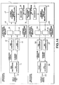
- Fig.19 shows, in a block diagram, a typical construction of the decoder 31 shown in Fig.14.
- Picture data transmitted over the transmission channel, that is the recording medium 3 is received by a reception circuit, not shown, or reproduced by a reproducing circuit, also not shown, so as to be subsequently transiently stored via an input terminal 80 in a reception buffer 81.
- the picture data thus stored transiently is supplied to a variable length decoding circuit 82 of a decoding circuit 90.
- variable length decoding circuit 82 then decodes the data supplied from the reception buffer 81 by variable length decoding and outputs the motion vector, prediction mode, prediction flag and the DCT flag to a motion compensation circuit 87, while outputting the quantization step data and decoded picture data to the inverse quantization circuit 83.
- the inverse quantization circuit 83 inverse-quantizes the picture data supplied from the variable length decoding circuit 82 depending on the quantization step data supplied thereto to output the inverse-quantized data to an IDCT circuit 84.
- Output data from the inverse quantization circuit 83, that is the DCT coefficients, are processed with inverse DCT by the IDCT circuit 84 so as to be supplied via a converting circuit 88 to a processor 85.
- Picture data supplied from the IDCT circuit 84 are matched by the converting circuit 88 based on the prediction flags and the DCT flags supplied to the converging circuit 88.
- the data supplied to the processor 85 are the data of the I-picture
- the data are outputted by the processor 85 so as to be supplied to and stored in the forward predictive-coded picture section 86a in the frame memory 86 via the converting circuit 89 for generating predictive-coded picture data for the picture data (data of the P- or B-picture) subsequently entered to the processor 85.
- the data are also outputted by a converting circuit 89 to the format converting circuit 32 shown in Fig.14 via an output terminal 91.
- the picture data supplied to the processor 5 is the data of the forward prediction mode, and is the data of the P-picture having the picture data of an immediately previous frame as the predictive-coded picture data
- the picture data (I-picture data) of the immediately previous frame stored in a forward predictive-coded picture section 86a of a frame memory 86, is read out and motion-compensated by the motion compensation circuit 87 depending on the motion vector outputted from the variable length decoding circuit 82.
- the motion-compensated data is summed in the processor 85 to the picture data supplied from the IDCT circuit 84 (the difference data) and the resulting sum data is outputted.
- the sum data that is the data of the decoded P-picture, is supplied to and stored in a backward predictive-coded picture section 86b within the frame memory 86 via the converting circuit 89 for generating the prediction picture data for the picture data subsequently entered to the processor 85, that is the B- or P-picture data.
- the data is the P-picture data and is intra-picture prediction mode data
- the data is not processed in the processor 85, as is the I-picture data, and is directly transmitted to and stored as it is in the backward predictive-coded picture section 86b via the converting circuit 89. Since the P-picture is the picture to be displayed next to the following B-picture, it is not as yet outputted to the format converting circuit 32 at this time point. That is, as mentioned previously, the P-picture entered after the B-picture is processed and transmitted prior to the B-picture.
- the picture data supplied from the IDCT circuit 84 is the B-picture data
- the picture data of the I-picture stored in the forward predictive-coded picture section 86a, the picture data of the P-picture stored in the backward predictive-coded picture section 86b, or both of these picture data are read out responsive to the predictive mode supplied from the variable length coding circuit 82, that is to the forward prediction mode, backward prediction mode or to the bidirectional prediction mode, respectively, and motion-compensated by the motion compensation circuit 87 depending on the motion vector outputted by the variable length decoding circuit 82 for generating the predictive-coded picture.
- Such predictive-coded picture is not generated if no motion compensation is required, that is if the prediction mode is the intra-picture prediction mode.
- the data motion-compensated in this manner by the motion compensation circuit 87 is summed in the processor 85 to an output of the converting circuit 88.
- This sum output is transmitted via the converting circuit 89 and the output 91 to the format converting circuit 32 shown in Fig.14. Since the sum output is the B-picture data which is not utilized for generating a prediction picture for other pictures, it is not stored in the frame memory 86.
- picture data of the P-picture stored in the backward prediction picture section 86b is read out and transmitted via the motion compensation circuit 87 to the processor 85.
- the motion compensation is not performed at this time.
- the circuits corresponding to the prediction mode changeover circuit 52 and the DCT mode changeover circuit 55 in the encoder shown in Fig.16 are not shown.
- the processing operation performed by these circuits that is the operations of reverting the configuration having odd field line signals and even field line signals separated from one another to the original configuration having these signals mixed with one another, is executed by the motion compensation circuit 87.
- processing of luminance signals has been explained in the foregoing, processing of the chrominance signals is executed in a similar manner, except that the motion vector employed for the luminance signals, which is reduced by one half in each of the vertical and horizontal directions, is employed for the chromiance signals.
- a value indicating the fineness of quantization that is the width of quantization, or the quantization stepsize. Even numbers of from 2 to 62 are employed a the width of quantization.
- the width of quantization is expressed by the quantization characteristics (QUANT). Integers of from 1 to 31 are employed for expressing the quantization characteristics which indicate the stepsize descriptions.
- the width of quantization is a value twice the value of the quantization characteristic.
- the width of quantization is required for compressing a picture in general to a target data volume. It is however extremely difficult to compress a picture having statistic properties deviated significantly from those of a general picture using the above-mentioned width of quantization, for example, to compress a picture exhibiting extremely low pixel correlation or a picture approximated to a white noise by DCT encoding which takes advantage of coefficient concentration in the frequency domain. That is, in such case, a picture cannot be compressed to a target size even if the maximum value 31 of the quantization characteristics is employed.
- the compressed bit stream is frequently controlled by the target transmission rate.
- the above-mentioned quantization characteristics are inversely proportionate to or, more accurately, logarithmically related with the number of generated bits of the picture data quantized on the basis of the above-mentioned quantization characteristics.
- the quantization characteristics are changed by one, the amount of the generated bits is changed significantly. If, for example, the quantization characteristics are changed from 1 to 2, the amount of the generated bits is reduced substantially by one half. This indicates that, if the quantization characteristics are within a small range, the interval between neighboring values of the quantization characteristics is so broad as to render it difficult to finely control the amount of the generated bits.
- the quantization characteristics are in a broader range, the amount of the generated bits is scarcely changed even if the quantization characteristics are changed by one. If, for example, the quantization characteristics are changed from 30 to 31, the amount of bit generation for the quantization characteristics of 31 is not changed by more than 5% from that for the quantization characteristics of 30. This indicates that the interval between neighboring values of the quantization characteristics is unnecessarily narrow for the larger range of values of the quantization characteristics.
- index number quantization operative quantization characteristics decimal expression binary expression 0 00000 1.0 0000001.0 1 00001 1.5 0000001.1 2 00010 2.0 0000010.0 3 00011 2.5 0000010.1 4 00100 3.0 0000011.0 5 00101 3.5 0000011.1 6 00110 4.0 0000100 7 00111 5.0 0000101 8 01000 6.0 0000110 9 01001 7.0 0000111 10 01010 8.0 0001000 11 01011 9.0 0001001 12 01100 11.0 0001011 13 01101 13.0 0001101 14 01110 15.0 0001111 15 01111 17.0 0010001 16 10000 19.0 0010011 17 10001 21.0 0010101 18 10010 23.0 0010111 19 10011 27.0 0011011 20 10100 31.0 0011111 21 10101 35.0 0100011 22 10110 39.0 0100111 23 10111 43.0 0101011 24 11000 47.0 0101111 25 11001 51.0 0110011 26 11010 55.0 0110111 27 11011 59
- quantization characteristics mapped to the nonlinear sequence quantization characteristics are given as table values mapped to the non-linear sequence of numbers, so that it becomes necessary to provide a arrangement for storing table values in the encoding/decoding apparatus. As a result thereof, the size of the hardware of the encoding/decoding apparatus is increased.
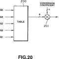
- a conventional inverse quantizer making use of quantization characteristics of the non-linear sequence of numerals is shown schematically in Fig.20.
- the quantization characteristics of the non-linear sequence of numbers are stored in a table 200 constituted by a ROM, and 8-bit data of the quantization characteristics are read out from the table 200.
- the quantization characteristics are multiplied in a multiplier 201 by an n-bit conversion coefficient for the quantized picture data for inverse-quantizing the quantized data.
- a large-size circuit is required for both the table 200 and the multiplier 201 in the inverse quantizer.
- an encoding method for picture signals in which input picture signals are quantized and subsequently encoded comprising setting a value of the quantization information employed for expressing an index of powers of 2 as the first quantization information among the quantization information, setting a value corresponding to a coefficient multiplied by the powers of 2 as the second quantization information among the quantization information, and performing quantization based on the non-linear quantization characteristics (QUANT) expressed using a product of said coefficient and the powers of 2.
- QUANT non-linear quantization characteristics
- a picture signal decoding method in which transmitted encoded data is inverse-quantized and subsequently decoded for restoring the picture data, wherein, at the time of inverse quantization, the non-linear quantization characteristics are reproduced by multiplying powers of 2 by a coefficient to be multiplied by the powers of 2, using a value for expressing an index of the powers of 2 as the first quantization information among the quantization information and a value corresponding to the coefficient as the second quantization information.
- the quantization characteristics by using k as the first quantization information which is a value for expressing the index of the powers of 2, k being a positive integer, and by using (i/2 + j) as the second information corresponding to the coefficient multiplied by the powers of 2, k being a positive integer and j being 0 or 1, and to employ the quantization characteristics multiplied by a constant as the width of quantization.
- the quantization information comprising the first quantization information and the second quantization information is represented by five bits and the relation between the quantization information k , i and j and the quantization characteristics is set as shown in Table 1, 2, 3 or 4.
- the quantization characteristics are represented by a binary number, there exists at least one effective bit in four consecutive bits.
- the encoded data is added thrice, and the resulting sum is shifted by bits as set by the first quantization information k .
- the quantization characteristics are found by using m as the first quantization information which is a value for expressing the index of the powers of 2, m being a value (integer) required for expressing desired quantization characteristics, and by using ⁇ i as the second information corresponding to the coefficient multiplied by the powers of 2, ⁇ i being 0 or 1, i being equal to 1 ⁇ n, and wherein the quantization characteristics multiplied by a constant are employed as the width of quantization.
- the quantization information comprising the first quantization information and the second quantization information is represented by (L + n) bits.
- the relation between the quantization information m , ⁇ i and the quantization characteristics is set as shown in the Tables 3 or 6.
- the encoded data is added twice and the resulting sum is shifted by three bits.
- a picture signal encoding method in which a picture signals is encoded using a pre-set prediction picture signal, the resulting encoded signal is processed in a pre-set manner and subsequently quantized and in which the resulting quantized signal has variable length coded, wherein the amount of bits generated on linear quantization is evaluated, a linear/ non-linear quantization changeover signal, indicating the quantization method, is generated based on the results of evaluation, and, if the linear/ non-linear quantization changeover signal indicates non-linear quantization, the quantization is performed based on non-linear quantization characteristics (QUANT) represented by powers of 2 and a coefficient multiplied by the powers of 2, with a value for expressing an index of the powers of 2 as the first quantization information among the quantization information and a value corresponding to said coefficient as the second quantization information.
- QUANT non-linear quantization characteristics
- the evaluation of the amount of the generated data is made on the frame basis.
- a picture signal encoding apparatus in which an input picture signal is quantized and subsequently encoded, comprising an encoding unit for encoding the input picture signal using a pre-set prediction picture signal, a converting unit for performing a pre-set conversion processing operation on the signal encoded by said encoding unit, a quantization unit for quantizing an output signal of said converting unit based on the non-linear quantization characteristics (QUANT) represented by powers of 2 and a coefficient multiplied by the powers of 2, with a value for expressing an index of the powers of 2 as the first quantization information among the quantization information and a value corresponding to said coefficient as the second quantization information, and a variable length encoding unit for variable length encoding the quantized signal.
- QUANT non-linear quantization characteristics
- a picture signal encoding apparatus in which an input picture signal is quantized and subsequently encoded, comprising an encoding unit for encoding the input picture signal using a pre-set prediction picture signal, a converting unit for performing a pre-set conversion on the signal encoded by the encoding unit, an evaluating unit for evaluating the amount of bits generated on linear quantization, a changeover signal generating unit for generating a linear/non-linear changeover signal indicating the quantization method depending on the result of evaluation by the evaluating unit, a first quantization unit for performing linear quantization on signals from the converting unit based on the non-linear quantization characteristics (QUANT) represented by powers of 2 and a coefficient multiplied by the powers of 2, using a value for expressing an index of the powers of 2 as the first quantization information among the quantization information and a value corresponding to the coefficient as the second quantization information, if the linear/non-linear changeover signal from said changeover signal generating unit indicates non
- QUANT non-linear
- the evaluating unit evaluates the amount of the generated bits on the frame basis.
- the linear/ non-linear quantization changeover signal indicating which of the linear/ non-linear quantization is to be used indicates non-linear quantization
- the non-linear quantization characteristics are reproduced by multiplying powers of 2 by a coefficient to be multiplied by the powers of 2, using a value for expressing an index of the powers of 2 as the first quantization information among the quantization information and a value corresponding to said coefficient as the second quantization information, and the encoded data is inverse-quantized based on the reproduced nonlinear quantization characteristics (QUANT).
- the linear inverse quantization and non-linear inverse quantization are performed on the frame basis.
- a picture signal decoding apparatus in which data obtained by variable length decoding the transmitted picture data is inverse-quantized and the inverse-quantized data is decoded for restoring picture data, comprising a variable length decoding unit for variable length decoding the transmitted picture data, an inverse quantization unit for reproducing the quantization characteristics by multiplying powers of 2 by a coefficient, using a value for expressing an index of the powers of 2 as the first quantization coefficient among the quantization coefficient, and a value corresponding to the coefficient to be multiplied by the powers of 2 as the second quantization information among the quantization coefficient, and inverse-quantizing the quantized data based on reproduced quantization characteristics (QUANT), and a converting unit for performing a pre-set operation on the inverse-quantized data.
- QUANT reproduced quantization characteristics
- the inverse quantization unit comprises a table section for converting the first quantization information, shifting means for shifting the second quantization information based on the first quantization information, addition means for adding an output of a table to an output of the shifting means, and a multiplication section for multiplying the quantized data by an output of the addition means.
- the inverse quantization unit comprises a table for converting the first quantization information, addition means for summing an output of the table to the second quantization information, multiplication means for multiplying an output of the addition means by the quantized data, and shifting means for shifting an output of the multiplication means by a number of bits as set by the first quantization information.
- the multiplication means is constituted by a three-stage multiplier.
- the inverse quantization unit comprises a table for converting the first quantization information, addition means for summing an output of the table to the second quantization information, selecting means for selecting one of the output of the addition means and the linear quantization information depending on the linear/ non-linear quantization information depending on the linear/ non-linear quantization changeover signal decoded by the variable length decoding section and transmitted along with the picture data, multiplication means for multiplying an output of the selecting means and the quantized data, and shifting means for shifting an output of the multiplication means by bits as set by the first quantization information only when the linear/ non-linear quantization changeover signal indicates non-linear quantization.
- the multiplication means is constituted by a three-stage multiplier.
- the quantization characteristics are converted into values of a non-linear sequence of numbers, and a conversion method for conversion into this non-linear sequence of numbers is selected appropriately.
- the quantization and inverse quantization are performed by only a multiplier with a smaller number of stages and processing operations.
- the quantization and inverse quantization are performed by only addition and shifting.
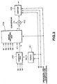
- Fig.1 illustrates a schematic arrangement of a circuit for reproducing quantization characteristics within an encoding apparatus and a decoding apparatus for picture signals according to the present invention.
- Fig.2 shows a schematic arrangement of a shifter 110 in Fig.1.
- Fig.3 shows a schematic arrangement of an inverse quantization circuit in the encoding apparatus and decoding apparatus for picture signals according to the present invention.
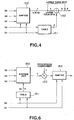
- Fig.4 illustrates a schematic arrangement of a circuit for reproducing quantization characteristics within an encoding apparatus and a decoding apparatus for picture signals according to a third embodiment of the present invention.
- Fig.5 shows a schematic arrangement of a shifter 110 in Fig.1.
- Fig.6 shows a schematic arrangement of an inverse quantization circuit in the encoding apparatus and decoding apparatus for picture signals according to the third embodiment of the present invention.
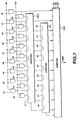
- Fig.7 shows a schematic arrangement of an inverse quantization circuit in the encoding apparatus and decoding apparatus for picture signals according to a fourth embodiment of the present invention.
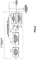
- Fig.8 illustrates a schematic arrangement of a quantization circuit within an encoding apparatus for picture signals according to the present invention.
- Fig.9 illustrates the principle of high efficiency encoding.
- Fig.10 illustrates picture type in compressing picture data.
- Fig.11 illustrates the principle of encoding moving picture signals.
- Fig.12 illustrates a GOP structure for moving picture signals.
- Fig.13 illustrates the sequence of unpitying, encoding, decoding and outputting picture signals.
- Fig.14 is a block circuit diagram showing a typical structure of a conventional encoding/decoding apparatus.
- Fig.15 illustrates the operation of format conversion in the format converting circuit 17 shown in Fig.14.
- Fig.16 is a block circuit diagram showing a typical structure of the encoder 18 shown in Fig.14.
- Fig.17 illustrates the operation of the prediction mode changeover circuit 52 shown in Fig.16.
- Fig.18 illustrates the operation of the DCT mode changeover circuit 52 shown in Fig.16.
- Fig.19 is a block circuit diagram showing a typical structure of the decoder 31 shown in Fig.14.
- Fig.20 illustrates a schematic arrangement of a conventional non-linear quantization circuit.
- the binary numbers for expressing indices or exponents of powers of 2 in the quantization information represent the first quantization information
- the binary numbers corresponding to the coefficients to be multiplied by the values of the powers of 2 represent the second quantization information
- quantization or inverse quantization is carried out based on the quantization characteristics (QUANT) represented by the nonlinear sequence of numbers expressed by products of the values of the powers of 2 and the above-mentioned coefficients.
- QUANT encoding or decoding of picture signals is performed by an encoder or a decoder, respectively.
- variable length coded data are contained in the bit stream encoded by the MPEG system. Therefore, a special code is required which enables monistical decoding even if a variety of possible variable length coded data should have occurred during decoding from an arbitrary point.
- the special code is a code consisting of 23 or more consecutive 0's.
- the quantization characteristics (QUANT) in which the totality of bits in the quantization information is 0 is inhibited to limit the variable length code data other than the above special code data lest 23 or more 0s should occur for any combinations of the other variable length code data.
- the sequence represented by the equation (1) is an arithmetic prpgression having a constant difference between two adjacent terms equal to a power of 2, if the quantization information is thought to be constant. If the number expressed by the quantization information j is p , the constant difference is changed over at an interval of 2 ⁇ p.
- k , j and i of the quantization information are 2 bits, 2 bits and 1 bit, respectively, totalled at 5 bits, and the quantization characteristics (QUANT) associated therewith, inclusive of the binary representation, are also shown.
- the five bits of the quantization information are expressed as (Q1 Q2 Q3 Q4 Q5), beginning from the MSB.
- the first two bits of the quantization information k(Q1 Q2) represent the first quantization information for expressing the indices for the powers of 2.
- two bits j (Q3 Q4) and one bit i (Q5) represent the second quantization information which is a value corresponding to the coefficient to be multiplied by the powers of 2 of the equation (1).
- the method and apparatus for encoding/decoding of picture signals employing the method for finding the quantization characteristics may be rendered interchangeable with the method and apparatus for encoding/decoding of picture signals employing the conventional method for finding the quantization characteristics.
- the groups of the quantization characteristics (QUANT) are indicated as X.
- the quantization characteristics (QUANT) may be expressed in terms of ⁇ and X by an equation ⁇ + X ⁇ 2 n , where n is a natural number.
- the groups each composed of eight values may be expressed by 0 + X, 4 + 2X, 12 + 4X and 28 + 8X, beginning from the leading end group.
- the circuit provided within the picture signal decoding apparatus for reproducing quantization characteristics by the conversion into the non-linear sequence of numbers shown in Table 8 is shown schematically in Fig.1.
- the sequence of numbers of each group X may be expressed by X ⁇ 2 n , n being a natural number, if the quantization information (Q3 Q4 Q5) is entered into a shifter 110 and shifted using the values of the quantization information (Q1 Q2). That is, if the quantization information (Q1 Q2) is (0 0), (0 1), (1 0) or (1 1), the quantization information (Q3 Q4 Q5) is shifted by 0, 1, 2 or 3 bits, respectively.
- Table 9 shows the values of the quantization information (Q1 Q2), entered to a table 111, a value of an output S1, issued after conversion by the table 111 and a value S2 sequentially read out in the table 111, as mentioned above.
- Q1 Q2 S1 S2 0 0 000 0 0 1 001 4 1 0 011 12 1 1 111 28
- the construction of the shifter 110 shown in Fig.1 is shown schematically in Fig.2.
- the quantization information (Q3 Q4 Q5), entered at AND gates 121 to 132, is changed over depending on the shift amount generated on the basis of quantization information (Q1 Q2) by a shift amount generator 120 and is transmitted through OR gates 133, 136 and ExOR gates 134, 135.
- the resulting quantization information is outputted at bit 0 output terminal b[0] to bit 5 output terminal [5].
- the four bits of the resulting sum signal and the lower three bits of the value X ⁇ 2 n appended thereto give the 7-bit quantization characteristics (QUANT) as reproduced values.
- the circuit arrangement for finding the above-described nonlinear quantization characteristics is smaller in size than the circuit arrangement for finding the conventional non-linear quantization characteristics shown in Fig.7.
- the reason is that the conventional non-linear quantization characteristics are destitute of periodicity and reference must be had incidentally to the table so that a large number of gates is required.
- the quantization characteristics thus produced are multiplied by the conversion coefficient for the quantized picture data (the quantization data) by way of inverse quantization. Since the four of the seven bits are effective bits, as may be seen from Table 8, a three-stage multiplier may be used for multiplying the quantization characteristics by the conversion coefficient as the quantized data (the quantization data) of the picture signals.
- the arrangement of the inverse quantization circuit within the picture signal encoding and decoding apparatus is shown schematically in Fig.3.
- the quantization information (Q1 Q2) entered to a table 141 is supplied to an addition unit 140 after conversion into a value S3 indicated in Table 10.
- S3 indicated in Table 10.
- the value S3 and the quantization information (Q3 Q4 Q5) are summed together and the resulting sum is transmitted to a signal switching unit 144.
- the quantization information (Q3 Q4 Q5) for carrying out the linear quantization and MSB equal to 0 of the quantization information for carrying out the non-linear quantization.
- a linear/non-linear quantization signal for selecting which of the linear and non-linear quantization is to be carried out.
- the linear quantization herein means that the values of the quantization information expressed as the binary values are related linearly with the values of the widths of quantization, that is the quantization step sizes.
- the non-linear quantization means that the values of the quantization information expressed as the binary values are related non-linearly with the values of the widths of quantization.
- the quantization information (Q1 Q2 Q3 Q4 Q5) for linear quantization is selected and transmitted to a multiplier 142.
- the 4-bit quantization signal from the addition unit 140 and 0 as the MSB of the quantization information are selected and transmitted to the multiplier 142.
- the multiplier 142 multiplies the input quantization information with the n-bit conversion coefficient to give a product which is outputted to a shifter 143.
- the quantization information (Q1 Q2) and the above-mentioned linear quantization /non-linear quantization switching signal are entered to the shifter 143. If the linear quantization has been selected by the linear quantization /non-linear quantization switching signal, the shifter 143 directly transmits the output of the multiplier 142 as the playback output. Conversely, if the non-linear quantization has been selected by the linear quantization /non-linear quantization switching signal, the shifter 143 shifts the output of the multiplier 142 with the amount of shift produced on the basis of the input quantization information (Q1 Q2), as shown in Table 11, to output the shifted data as the playback data.
- the term (i/2 + j) corresponds to the second quantization information (Q3 Q4 Q5) entered to the addition unit 140
- the term (4 - 4/2 k )) corresponds the an output of the table 141
- the term 2 k corresponds to the amount of shift in the shifter 143.
- A Coeff ((i/2 + j) + (4 - 4/2 k )) ⁇ 2 (k+1)
- the shifter 143 employed for finding the playback value A is simpler in construction.
- the multiplier 142 of a smaller number of stages may also be employed, which is capable of multiplying n bits of the conversion coefficient, 4 bits of the output data of the switching unit 144 and the MSB.
- the maximum value that can be assumed by the quantization characteristics is 56.0, with the quantization width being 112.
- the white noise for example, is entered in actual pictures, larger values of quantization characteristics are required.
- the following two methods may be employed.
- the first method is to allocate larger values of the quantization characteristics, such as 64, 96 or 128, for the quantization information of "00000" binary, which is currently not employed. If 64 or 128 is allocated as the values of the quantization characteristics, processing may be facilitated because shifting by a shifter suffices for multiplication in inverse quantization. If 96 is allocated as the value of the quantization characteristics, processing may similarly be facilitated because a single-stage addition unit suffices.
- the second method is to allocate the values of the quantization characteristics of 64, 96 or 128 for the quantization information of "11111" binary, in consideration that a long sequence of "0" is likely to be produced if the quantization information "00000" binary is employed.
- the quantization information of the fourth group is found by intentionally setting the maximum value of the shift amount indicated by the quantization information k so as to be larger to disregard the continuity of the quantization information k .
- the maximum possible value of the quantization characteristics is 84.0 which is large enough to accommodate special inputs such as the white noise. This method is desirable in controlling the coding because it renders it possible to provide continuous quantization characteristics up to the maximum value.
- the quantization information "00000" is inhibited, as in the above-described first embodiment.
- the circuit for reproducing the quantization characteristics provided within the picture signal decoding apparatus for reproducing the quantization characteristics by conversion into a non-linear sequence of numbers shown in Table 12, is shown schematically in Fig.4.
- the values of X ⁇ 2 n , n being a natural number, may be expressed by entering the quantization information (Q3 Q4 Q5) to a shifter 150 and by shifting the quantization information (Q3 Q4 Q5) using the values of the quantization information (Q1 Q2). That is, the quantization information (Q3 Q4 Q5) is shifted by 0. 1, 2 or 4 bits if the quantization information (Q1 Q2) is (0 0), (0 1), (1 0) or (1 1), respectively.
- Fig.5 shows a schematic construction of the shifter 150 shown in Fig.4.
- the quantization information (Q3 Q4 Q5) entered to AND gates 161 to 172 is changed over responsive to the shift amount produced in a shift amount generator 160 based on the quantization information (Q1 Q2), and is transmitted via OR gates 173, 175 and an ExOr gate 174 so that the quantization information is outputted at a bit 0 output terminal b[0] to bit 6 output terminal [6].
- the five-bit sum value is appended to lower three bits of the value X ⁇ 2 n to reproduce the 8-bit quantization characteristics (QUANT).
- the values sequentially read out from the table 151 are those shown in Table 9, as in the above-described first embodiment.
- the inverse quantization circuit in the encoding /decoding apparatus for picture signals is shown schematically in Fig.6.
- the quantization information (Q1 Q2) entered to a table 181 is converted into the values S4 shown in Fig.13 so as to be supplied to an addition unit 180.
- the value S4 from the table 181 and the quantization information (Q3 Q4 Q5) are summed together and the resulting sum is multiplied in a multiplier 182 with an n-bit conversion coefficient.
- the resulting product is shifted in a shifter 183 based on the quantization information (Q1 Q2) for reproducing picture data.
- the number of bits from the multiplier 183 of the inverse quantization circuit 182 in the present third embodiment differs from the number of bits from the multiplier 142 of the inverse quantization circuit in the above-described first embodiment.
- the playback value A of the picture data may be found from the equation (4).
- the shifter 183 employed for finding the playback value A is simpler in construction.
- the multiplier 182 of a smaller number of stages may also be employed, which is capable of multiplying n bits of the conversion coefficient and 5 bits of the output data of the multiplier 180.
- QUANT quantization characteristics
- the signals are quantized with values of the index m being integers of from 0 to 7 and the fineness n of the quantization characteristics of 2, as a typical example for the equation (6).
- the value (m - 1) is employed in the equation (6) in place of m as the index of the power, there is no essential difference whether the index m or (m - 1) is employed.
- the mapping may be determined monistically by the equation (6), so that there is no necessity of providing a memory for storing the mapping data.
- the following code data is transmitted for transmitting the quantization information according to the equation (6).
- the quantization information m it is necessary to transmit integers of from O to 7, so that three bits are required.
- the quantization information ⁇ 1 and ⁇ 2 each one bit is required, so that a total of five bits are required.
- the number of bits of five is precisely that required for transmitting the figures of from 1 to 31, so that compatibility of the system operating under the conventional quantization characteristics with the system operating under the quantization characteristics according to the present invention may be maintained.
- the quantization information m is represented by the first three bits (Q1 Q2 Q3) binary, and the quantization information ⁇ 1 and the quantization information ⁇ 2 are represented each by one bit (Q4 Q5).
- the inverse quantization when employing the mapping to the non-linear sequence shown in Table 14 is now considered. If the non-linear sequence shown in Table 14 is represented by binary numbers, only three bits become “1" simultaneously in any of the binary numbers. Consequently, addition is performed twice at the maximum and two adders suffice. Besides, the bits "1" occur consecutively without occurring ar random, so that it suffices to shift data to a desired place by a shifter placed downstream of two-stage adders.
- the inverse quantization circuit according to the present invention which is based on the above-described principle, is shown in Fig.7.
- the inverse quantization device according to the present invention is made up of two full adders 190, 191 and a shifter 192. The shifter shifts data left by a number of bits shown in Table 15 depending on the value of (Q1 Q2 Q3). At this time, the LSB is padded with 0.
- the fineness of quantization characteristics up to the third place below the binary point in binary representation is defined, as shown in Table 14.
- the fineness of quantization characteristics accepted by the quantization circuit is determined independently. For example, if the fineness of quantization characteristics accepted by the quantization circuit is up to the first place below the binary point in binary representation, the quantization information shown in Table 14, having the excessive fineness of quantization characteristics are inhibited. The quantization characteristics limited is this manner are shown in Table 17. In the fifth embodiment, the inhibited quantization information cannot be employed.
- the quantization information having the excessive fineness of quantization characteristics is changed as to the manner of allocation thereof so as to represent the near-by quantization characteristics having acceptable fineness, instead of inhibiting the quantization information having the excessive fineness of quantization characteristics.
- This embodiment is shown in Table 18, in which the quantization information representing quantization characteristics of, for example, 0.5, is "000xx", x indicating "don't care' thus showing that the bit in these positions may be 0 or 1.
- variable length coded data are contained in the bit stream encoded by the MPEG system. Therefore, a special code is required which enables monistical decoding if, when decoding is made from an arbitrary point, a variety of possible variable length coded data should have occurred.
- the special code is a code consisting of 23 or more consecutive 0's. In this consideration, limitations are imposed on the variable length code data other than the above special code data lest 23 or more 0s should occur for any combinations of the other variable length code data.
- the schematic arrangement of the encoding apparatus for picture signals according to the present invention is similar to the conventional encoding apparatus shown in Fig.16.
- the inverse quantization circuit 60 has one of the schematic arrangements shown in Figs.3, 6 and 7, while the quantization circuit 57 has a schematic arrangement shown in Fig.8.
- the signals from the DCT circuit 56 shown in Fig.16 are transmitted to the quantization circuit 57 shown in Fig.8 and thence to a maximum coefficient selecting circuit 210.
- a value obtained on dividing the maximum coefficient by the maximum quantization width 62 employed for linear quantization is compared to a maximum value of 256 of the quantization level. If the value is equal to or larger than the maximum quantization width, a quantization characteristic selecting circuit 211 selects the quantization characteristics for linear quantization. At this time, the quantization characteristic selecting circuit 211 outputs a quantization selecting signal indicating that the linear quantization has been selected to a signal changeover switch 212 and to the variable length coding circuit 58 shown in Fig.16.
- the signal changeover switch 212 is set to a fixed terminal a so that the output of the quantization characteristic selecting circuit 211 is transmitted via the terminal a of the signal changeover switch 212 to a linear quantization circuit 213.
- linear quantization is performed on the data with the linear quantization characteristics and the resulting linear-quantized data is outputted to the variable length coding circuit 58 and to the inverse quantization circuit 60.
- variable length coding circuit 58 Since not only the quantization characteristic selecting signal but also the quantization width (quantization scale) is supplied to the variable length coding circuit 58, the variable length coding circuit 58 performs variable length coding using the quantization width.
- the quantization characteristic selecting circuit 211 selects the quantization characteristics for nonlinear quantization.
- a quantization selecting signal from the quantization characteristic selecting circuit 211 indicating that the non-linear quantization has been selected is outputted to the signal selecting switch 212 which is changed over to a fixed terminal b.
- An output of the quantization characteristic selecting circuit 211 is transmitted via the terminal b of the signal changeover switch 212 to a non-linear quantization circuit 214 via the terminal b of the signal changeover switch 212 so that non-linear quantization is performed in accordance with non-linear quantization characteristics.
- the non-linear quantized data are outputted to the variable length coding circuit 58 and to the inverse quantization circuit 60.
- variable length coding circuit 58 Since not only the quantization characteristic selecting signal but also the quantization width (quantization scale) is supplied to the variable length coding circuit 58, as in the case of the linear quantization, the variable length coding circuit 58 performs variable length coding using the quantization width.
- the maximum coefficient selecting circuit 210 may check the flag indicating the quantization characteristics, prescribed in the MPEG system, to decide which of the linear quantization or the non-linear quantization is to be performed.
- the maximum coefficient selecting circuit 210 may check the dynamic range to decide which of the linear quantization or the non-linear quantization is to be performed.
- the schematic arrangement of the decoding apparatus for picture signals according to the present invention is similar to that of the conventional decoding apparatus shown in Fig.19.
- the inverse quantization circuit 83 may have any one of the schematic arrangements shown in Figs.3, 6 and 7.
- a picture signal encoding apparatus comprising an encoding unit for encoding the input picture signal using a pre-set prediction picture signal, a converting unit for performing a pre-set converting operation on the signal encoded by the encoding unit, an evaluating unit for evaluating the amount of bits generated on linear quantization, a changeover signal generating unit for generating a. linear/non-linear changeover signal.
- a first quantization unit for performing linear quantization on signals from the converting unit if the linear/non-linear changeover signal from the changeover signal generating unit indicates the linear quantization
- a second quantization unit for performing linear quantization on signals from the converting unit based on the non-linear quantization characteristics (QUANT) represented by powers of 2 and a coefficient multiplied by the powers of 2, using a value for expressing an index of the powers of 2 as the first quantization information among the quantization information and a value corresponding to the coefficient as the second quantization information, if the linear/non-linear changeover signal from the changeover signal generating unit indicates non-linear quantization, and a variable length coding unit for performing variable length coding on output quantized signals of the first quantization unit or the second quantization unit, whereby the picture data may be quantized or inverse-quantized with quantization characteristics of a broad range and appropriate accuracy.
- QUANT non-linear quantization characteristics
- a picture signal decoding apparatus comprising a variable length decoding unit for performing variable length decoding on the transmitted picture data, an inverse quantization unit for reproducing the quantization characteristics by multiplying powers of 2 by a coefficient, using a value for expressing an index of the powers of 2 as the first quantization coefficient among the quantization coefficient, and a value corresponding to the coefficient to be multiplied by sad powers of 2 as the second quantization information among the quantization coefficient, and inverse-contusing the quantized data from the variable length coding unit based on reproduced non-linear quantization characteristic, and a converting unit for performing'a pre-set operation on the inverse-quantized data, whereby the picture data may be inverse-quantized with quantization characteristics of a broad range and appropriate accuracy.
- the quantization characteristics may be obtained which may be suitable in controlling the number of bits generated by encoding with high accuracy.
- the circuit arrangement since there is no necessity of storing the nonlinear sequence of numbers for quantization characteristics, the circuit arrangement is not increased in size and quantization and inverse quantization my be achieved using shifting operations and a multiplier having a reduced number of stages, the multiplier scale may be halved as compared with that in the conventional encoding /decoding method and encoding/decoding apparatus.
Landscapes
- Engineering & Computer Science (AREA)
- Multimedia (AREA)
- Signal Processing (AREA)
- Compression Or Coding Systems Of Tv Signals (AREA)
- Compression, Expansion, Code Conversion, And Decoders (AREA)
Applications Claiming Priority (6)
| Application Number | Priority Date | Filing Date | Title |
|---|---|---|---|
| JP29169792 | 1992-10-29 | ||
| JP291697/92 | 1992-10-29 | ||
| JP10177/93 | 1993-01-25 | ||
| JP1017793 | 1993-01-25 | ||
| JP6655093 | 1993-03-25 | ||
| JP66550/93 | 1993-03-25 |
Publications (2)
| Publication Number | Publication Date |
|---|---|
| EP0595562A1 true EP0595562A1 (fr) | 1994-05-04 |
| EP0595562B1 EP0595562B1 (fr) | 1999-05-19 |
Family
ID=27278868
Family Applications (1)
| Application Number | Title | Priority Date | Filing Date |
|---|---|---|---|
| EP93308439A Expired - Lifetime EP0595562B1 (fr) | 1992-10-29 | 1993-10-22 | Méthode et appareil pour quantifier et inverse-quantifier des signaux d'image |
Country Status (8)
| Country | Link |
|---|---|
| US (1) | US5663763A (fr) |
| EP (1) | EP0595562B1 (fr) |
| KR (1) | KR100335707B1 (fr) |
| CN (1) | CN1054486C (fr) |
| AU (1) | AU667970B2 (fr) |
| CA (1) | CA2108704C (fr) |
| DE (1) | DE69324993T2 (fr) |
| MY (1) | MY118444A (fr) |
Cited By (3)
| Publication number | Priority date | Publication date | Assignee | Title |
|---|---|---|---|---|
| EP0659023A3 (fr) * | 1993-12-16 | 1996-03-27 | Matsushita Electric Industrial Co Ltd | Méthode et appareil pour le codage avec compression de données d'image. |
| EP0693857A3 (fr) * | 1994-07-18 | 1998-02-11 | Thomson Consumer Electronics, Inc. | Préprocesseur pour l'élimination de contours dans des systèmes de compression vidéo |
| EP2493186A1 (fr) * | 2001-07-12 | 2012-08-29 | Dolby Laboratories Licensing Corporation | Procédé et système pour améliorer les informations de chrominance d'une image compressée |
Families Citing this family (42)
| Publication number | Priority date | Publication date | Assignee | Title |
|---|---|---|---|---|
| EP0726679B1 (fr) * | 1994-08-26 | 2006-05-31 | Sony Corporation | Procede et dispositif d'emission de donnees d'images comprimees |
| GB2305798B (en) * | 1995-09-28 | 1999-10-20 | Sony Uk Ltd | Spatial frequency-domain video signal processing |
| JP3360512B2 (ja) * | 1996-01-09 | 2002-12-24 | ソニー株式会社 | 固体撮像素子およびその読み出し方法 |
| US6208689B1 (en) * | 1996-03-04 | 2001-03-27 | Mitsubishi Denki Kabushiki Kaisha | Method and apparatus for digital image decoding |
| JP2830855B2 (ja) * | 1996-08-22 | 1998-12-02 | 日本電気株式会社 | 適応量子化制御装置 |
| CN100481946C (zh) * | 1998-03-20 | 2009-04-22 | 三菱电机株式会社 | 编码和解码及压缩图像的方法和装置 |
| US6298087B1 (en) * | 1998-08-31 | 2001-10-02 | Sony Corporation | System and method for decoding a variable length code digital signal |
| JP2002535935A (ja) * | 1999-01-21 | 2002-10-22 | コーニンクレッカ フィリップス エレクトロニクス エヌ ヴィ | データを量子化する方法及び装置 |
| US6765962B1 (en) * | 1999-12-02 | 2004-07-20 | Sarnoff Corporation | Adaptive selection of quantization scales for video encoding |
| KR20020070497A (ko) * | 2000-11-22 | 2002-09-09 | 코닌클리케 필립스 일렉트로닉스 엔.브이. | 비디오 신호 처리 |
| US8374237B2 (en) | 2001-03-02 | 2013-02-12 | Dolby Laboratories Licensing Corporation | High precision encoding and decoding of video images |
| US7227998B2 (en) * | 2002-06-11 | 2007-06-05 | Canon Kabushiki Kaisha | Image processing apparatus, control method of the same, computer program, and computer-readable storage medium |
| KR100436765B1 (ko) * | 2002-07-12 | 2004-06-23 | 삼성전자주식회사 | 디지털 비디오 시스템의 신호처리장치 및 방법 |
| WO2004038650A1 (fr) | 2002-10-25 | 2004-05-06 | Silverbrook Research Pty Ltd | Codes de position cyclique indiquant une orientation |
| US7433519B2 (en) * | 2003-04-04 | 2008-10-07 | Avid Technology, Inc. | Bitstream format for compressed image data |
| US7403561B2 (en) * | 2003-04-04 | 2008-07-22 | Avid Technology, Inc. | Fixed bit rate, intraframe compression and decompression of video |
| US8218624B2 (en) | 2003-07-18 | 2012-07-10 | Microsoft Corporation | Fractional quantization step sizes for high bit rates |
| US7602851B2 (en) | 2003-07-18 | 2009-10-13 | Microsoft Corporation | Intelligent differential quantization of video coding |
| US10554985B2 (en) | 2003-07-18 | 2020-02-04 | Microsoft Technology Licensing, Llc | DC coefficient signaling at small quantization step sizes |
| US7738554B2 (en) | 2003-07-18 | 2010-06-15 | Microsoft Corporation | DC coefficient signaling at small quantization step sizes |
| US7580584B2 (en) | 2003-07-18 | 2009-08-25 | Microsoft Corporation | Adaptive multiple quantization |
| JP4201338B2 (ja) * | 2004-02-03 | 2008-12-24 | シャープ株式会社 | 画像処理装置、画像処理方法、画像表示装置、携帯用情報機器、制御プログラムおよび可読記録媒体 |
| US7801383B2 (en) | 2004-05-15 | 2010-09-21 | Microsoft Corporation | Embedded scalar quantizers with arbitrary dead-zone ratios |
| US8422546B2 (en) | 2005-05-25 | 2013-04-16 | Microsoft Corporation | Adaptive video encoding using a perceptual model |
| KR100651198B1 (ko) * | 2005-07-08 | 2006-12-01 | 노틸러스효성 주식회사 | 지폐 회수 장치 및 동작 방법 |
| US8503536B2 (en) | 2006-04-07 | 2013-08-06 | Microsoft Corporation | Quantization adjustments for DC shift artifacts |
| US8059721B2 (en) | 2006-04-07 | 2011-11-15 | Microsoft Corporation | Estimating sample-domain distortion in the transform domain with rounding compensation |
| US7974340B2 (en) | 2006-04-07 | 2011-07-05 | Microsoft Corporation | Adaptive B-picture quantization control |
| US8130828B2 (en) | 2006-04-07 | 2012-03-06 | Microsoft Corporation | Adjusting quantization to preserve non-zero AC coefficients |
| US7995649B2 (en) | 2006-04-07 | 2011-08-09 | Microsoft Corporation | Quantization adjustment based on texture level |
| US8711925B2 (en) | 2006-05-05 | 2014-04-29 | Microsoft Corporation | Flexible quantization |
| US8238424B2 (en) | 2007-02-09 | 2012-08-07 | Microsoft Corporation | Complexity-based adaptive preprocessing for multiple-pass video compression |
| US8498335B2 (en) | 2007-03-26 | 2013-07-30 | Microsoft Corporation | Adaptive deadzone size adjustment in quantization |
| US8243797B2 (en) | 2007-03-30 | 2012-08-14 | Microsoft Corporation | Regions of interest for quality adjustments |
| US8442337B2 (en) | 2007-04-18 | 2013-05-14 | Microsoft Corporation | Encoding adjustments for animation content |
| US8331438B2 (en) | 2007-06-05 | 2012-12-11 | Microsoft Corporation | Adaptive selection of picture-level quantization parameters for predicted video pictures |
| US8189933B2 (en) | 2008-03-31 | 2012-05-29 | Microsoft Corporation | Classifying and controlling encoding quality for textured, dark smooth and smooth video content |
| US8897359B2 (en) | 2008-06-03 | 2014-11-25 | Microsoft Corporation | Adaptive quantization for enhancement layer video coding |
| US8379715B2 (en) * | 2009-08-27 | 2013-02-19 | Nxp B. V. | System and method for video compression using non-linear quantization and modular arithmetic computation |
| KR101717667B1 (ko) | 2010-12-10 | 2017-03-20 | 삼성전자주식회사 | 전원공급유닛용 검사장치 |
| CN109738008B (zh) * | 2019-01-15 | 2021-01-08 | 深圳市对接平台科技发展有限公司 | 现场解析度分析平台 |
| US11818353B2 (en) * | 2021-05-13 | 2023-11-14 | Qualcomm Incorporated | Reduced complexity transforms for high bit-depth video coding |
Citations (2)
| Publication number | Priority date | Publication date | Assignee | Title |
|---|---|---|---|---|
| US4791483A (en) * | 1987-11-20 | 1988-12-13 | The Grass Valley Group, Inc. | Adaptive differential pulse code modulation video encoder |
| EP0424060A2 (fr) * | 1989-10-14 | 1991-04-24 | Sony Corporation | Méthode de codage de signaux vidéo et système de transmission à cette fin |
Family Cites Families (18)
| Publication number | Priority date | Publication date | Assignee | Title |
|---|---|---|---|---|
| US3707680A (en) * | 1970-05-20 | 1972-12-26 | Communications Satellite Corp | Digital differential pulse code modulation system |
| US4179710A (en) * | 1976-02-23 | 1979-12-18 | Nippon Electric Co., Ltd. | Predictive encoder with a non-linear quantizing characteristic |
| JPS57150275A (en) * | 1981-03-11 | 1982-09-17 | Fuji Photo Film Co Ltd | Adaptive quantizer |
| JPH065888B2 (ja) * | 1986-02-14 | 1994-01-19 | 富士写真フイルム株式会社 | 画像デ−タ量子化方法および装置 |
| JPS62222783A (ja) * | 1986-03-24 | 1987-09-30 | Kokusai Denshin Denwa Co Ltd <Kdd> | 動画像の高能率符号化方式 |
| US4885637A (en) * | 1986-07-26 | 1989-12-05 | Canon Kabushiki Kaisha | Encoder |
| US4698672A (en) * | 1986-10-27 | 1987-10-06 | Compression Labs, Inc. | Coding system for reducing redundancy |
| JP2783534B2 (ja) * | 1986-11-13 | 1998-08-06 | キヤノン株式会社 | 符号化装置 |
| US4725885A (en) * | 1986-12-22 | 1988-02-16 | International Business Machines Corporation | Adaptive graylevel image compression system |
| US4785356A (en) * | 1987-04-24 | 1988-11-15 | International Business Machines Corporation | Apparatus and method of attenuating distortion introduced by a predictive coding image compressor |
| JPH02226886A (ja) * | 1989-02-28 | 1990-09-10 | Sony Corp | データ伝送装置及び伝送方法 |
| JPH02243080A (ja) * | 1989-03-16 | 1990-09-27 | Nec Corp | テレビ信号符号化回路 |
| JPH0714209B2 (ja) * | 1989-12-20 | 1995-02-15 | 松下電器産業株式会社 | 動画像符号化装置 |
| US5010402A (en) * | 1990-05-17 | 1991-04-23 | Matsushita Electric Industrial Co., Ltd. | Video signal compression apparatus |
| JP3109854B2 (ja) * | 1991-04-23 | 2000-11-20 | キヤノン株式会社 | 画像符号化方法及び装置 |
| KR940011605B1 (ko) * | 1991-12-20 | 1994-12-22 | 삼성전자 주식회사 | 고정비트율 설정에 의한 영상압축방식 |
| KR0160610B1 (ko) * | 1992-04-07 | 1999-01-15 | 강진구 | 가변장부호화에 의한 영상압축방법과 신장방법 및 그 장치 |
| JP3245977B2 (ja) * | 1992-06-30 | 2002-01-15 | ソニー株式会社 | ディジタル画像信号の伝送装置 |
-
1993
- 1993-10-18 US US08/137,257 patent/US5663763A/en not_active Expired - Lifetime
- 1993-10-19 CA CA002108704A patent/CA2108704C/fr not_active Expired - Lifetime
- 1993-10-22 EP EP93308439A patent/EP0595562B1/fr not_active Expired - Lifetime
- 1993-10-22 DE DE69324993T patent/DE69324993T2/de not_active Expired - Lifetime
- 1993-10-27 MY MYPI93002229A patent/MY118444A/en unknown
- 1993-10-28 AU AU50358/93A patent/AU667970B2/en not_active Expired
- 1993-10-29 CN CN93119720A patent/CN1054486C/zh not_active Expired - Lifetime
- 1993-10-29 KR KR1019930023119A patent/KR100335707B1/ko not_active Expired - Lifetime
Patent Citations (2)
| Publication number | Priority date | Publication date | Assignee | Title |
|---|---|---|---|---|
| US4791483A (en) * | 1987-11-20 | 1988-12-13 | The Grass Valley Group, Inc. | Adaptive differential pulse code modulation video encoder |
| EP0424060A2 (fr) * | 1989-10-14 | 1991-04-24 | Sony Corporation | Méthode de codage de signaux vidéo et système de transmission à cette fin |
Non-Patent Citations (2)
| Title |
|---|
| GONZALES ET AL.: "DCT CODING FOR MOTION VIDEO STORAGE USING ADAPTIVE ARITHMETIC CODING", SIGNAL PROCESSING. IMAGE COMMUNICATION, vol. 2, no. 2, August 1992 (1992-08-01), AMSTERDAM NL, pages 145 - 154, XP000243474, DOI: doi:10.1016/0923-5965(90)90017-C * |
| LE GALL: "The MPEG video compression algorithm", SIGNAL PROCESSING. IMAGE COMMUNICATION, vol. 4, no. 2, April 1992 (1992-04-01), AMSTERDAM NL, pages 129 - 140, XP000273159, DOI: doi:10.1016/0923-5965(92)90019-C * |
Cited By (9)
| Publication number | Priority date | Publication date | Assignee | Title |
|---|---|---|---|---|
| EP0659023A3 (fr) * | 1993-12-16 | 1996-03-27 | Matsushita Electric Industrial Co Ltd | Méthode et appareil pour le codage avec compression de données d'image. |
| US5754696A (en) * | 1993-12-16 | 1998-05-19 | Matsushita Electric Industrial Co., Ltd. | Apparatus for compression-coding image data and method of the same based on quantification and frequency transform coefficient amplitude reduction |
| EP0693857A3 (fr) * | 1994-07-18 | 1998-02-11 | Thomson Consumer Electronics, Inc. | Préprocesseur pour l'élimination de contours dans des systèmes de compression vidéo |
| EP2493186A1 (fr) * | 2001-07-12 | 2012-08-29 | Dolby Laboratories Licensing Corporation | Procédé et système pour améliorer les informations de chrominance d'une image compressée |
| US10110908B2 (en) | 2001-07-12 | 2018-10-23 | Dolby Laboratories Licensing Corporation | Method and system for improving compressed image chroma information |
| US10158865B2 (en) | 2001-07-12 | 2018-12-18 | Dolby Laboratories Licensing Corporation | Method and system for improving compressed image chroma information |
| US10297008B2 (en) | 2001-07-12 | 2019-05-21 | Dolby Laboratories Licensing Corporation | Method and system for improving compressed image chroma information |
| US10504205B2 (en) | 2001-07-12 | 2019-12-10 | Dolby Laboratories Licensing Corporation | Method and system for improving compressed image chroma information |
| US11315216B2 (en) | 2001-07-12 | 2022-04-26 | Dolby Laboratories Licensing Corporation | Method and system for improving compressed image chroma information |
Also Published As
| Publication number | Publication date |
|---|---|
| KR100335707B1 (ko) | 2002-09-25 |
| CA2108704A1 (fr) | 1994-04-30 |
| AU667970B2 (en) | 1996-04-18 |
| MY118444A (en) | 2004-11-30 |
| US5663763A (en) | 1997-09-02 |
| AU5035893A (en) | 1994-05-12 |
| DE69324993T2 (de) | 1999-12-02 |
| CN1054486C (zh) | 2000-07-12 |
| CN1090115A (zh) | 1994-07-27 |
| KR940010807A (ko) | 1994-05-26 |
| EP0595562B1 (fr) | 1999-05-19 |
| DE69324993D1 (de) | 1999-06-24 |
| CA2108704C (fr) | 2004-05-04 |
Similar Documents
| Publication | Publication Date | Title |
|---|---|---|
| EP0595562B1 (fr) | Méthode et appareil pour quantifier et inverse-quantifier des signaux d'image | |
| KR100340369B1 (ko) | 화상부호화방법및장치 | |
| US5751359A (en) | Method for quantizing compressed video signals | |
| KR970005831B1 (ko) | 적응적 프레임/필드 변환 부호화를 이용한 영상 부호화기 | |
| KR0166722B1 (ko) | 부호화 및 복호화방법 및 그 장치 | |
| US6226327B1 (en) | Video coding method and apparatus which select between frame-based and field-based predictive modes | |
| KR100340370B1 (ko) | 화상신호전송방법및장치 | |
| JP3856262B2 (ja) | 動き補償符号化装置、動き補償符号化方法、及び動き補償符号記録媒体 | |
| KR960006762B1 (ko) | 화상부호화를 위한 효율적인 2차원 데이타의 주사선택회로 | |
| KR100273906B1 (ko) | 동화상가변비트속도부호화장치및방법 | |
| KR100396928B1 (ko) | 동화상부호화방법및동화상부호화장치 | |
| US6256349B1 (en) | Picture signal encoding method and apparatus, picture signal transmitting method, picture signal decoding method and apparatus and recording medium | |
| KR100364312B1 (ko) | 블록간예측부호화복호화장치및그방법 | |
| WO1995013682A1 (fr) | Procede de codage et de decodage d'animation, et support d'enregistrement et codeur d'animation | |
| JP3980659B2 (ja) | 動画像符号化方法及び装置、動画像復号化方法及び装置。 | |
| JPH06284412A (ja) | 画像信号符号化方法および画像信号符号化装置、画像信号復号化方法および画像信号復号化装置、ならびに画像信号記録媒体 | |
| JP3463291B2 (ja) | 圧縮ディジタル・ビデオ・シーケンスをデコードし表示する方法および装置 | |
| KR100568649B1 (ko) | 동화상복호화장치및동화상복호화방법 | |
| JP3689437B2 (ja) | 画像信号の符号化方法及び装置 | |
| JP3568392B2 (ja) | 動画像復号化装置 | |
| JP2002262293A (ja) | 動画像復号装置および動画像復号方法 | |
| KR100284696B1 (ko) | Mpeg 복호 블럭에서의 수평/수직 주파수 변환장치 | |
| JP3689626B2 (ja) | 画像信号の復号化方法及び装置 | |
| JPH07131793A (ja) | 映像信号高能率符号化装置 | |
| JPH04259182A (ja) | 動き補償予測フレーム間符号化装置 |
Legal Events
| Date | Code | Title | Description |
|---|---|---|---|
| PUAI | Public reference made under article 153(3) epc to a published international application that has entered the european phase |
Free format text: ORIGINAL CODE: 0009012 |
|
| AK | Designated contracting states |
Kind code of ref document: A1 Designated state(s): DE FR GB IT NL |
|
| 17P | Request for examination filed |
Effective date: 19941007 |
|
| 17Q | First examination report despatched |
Effective date: 19960912 |
|
| GRAG | Despatch of communication of intention to grant |
Free format text: ORIGINAL CODE: EPIDOS AGRA |
|
| RHK1 | Main classification (correction) |
Ipc: H04N 7/32 |
|
| RTI1 | Title (correction) | ||
| GRAG | Despatch of communication of intention to grant |
Free format text: ORIGINAL CODE: EPIDOS AGRA |
|
| GRAH | Despatch of communication of intention to grant a patent |
Free format text: ORIGINAL CODE: EPIDOS IGRA |
|
| GRAH | Despatch of communication of intention to grant a patent |
Free format text: ORIGINAL CODE: EPIDOS IGRA |
|
| GRAA | (expected) grant |
Free format text: ORIGINAL CODE: 0009210 |
|
| AK | Designated contracting states |
Kind code of ref document: B1 Designated state(s): DE FR GB IT NL |
|
| REF | Corresponds to: |
Ref document number: 69324993 Country of ref document: DE Date of ref document: 19990624 |
|
| ET | Fr: translation filed | ||
| PLBE | No opposition filed within time limit |
Free format text: ORIGINAL CODE: 0009261 |
|
| 26N | No opposition filed | ||
| REG | Reference to a national code |
Ref country code: GB Ref legal event code: IF02 |
|
| PGFP | Annual fee paid to national office [announced via postgrant information from national office to epo] |
Ref country code: FR Payment date: 20121031 Year of fee payment: 20 Ref country code: DE Payment date: 20121023 Year of fee payment: 20 |
|
| PGFP | Annual fee paid to national office [announced via postgrant information from national office to epo] |
Ref country code: GB Payment date: 20121019 Year of fee payment: 20 Ref country code: IT Payment date: 20121026 Year of fee payment: 20 |
|
| PGFP | Annual fee paid to national office [announced via postgrant information from national office to epo] |
Ref country code: NL Payment date: 20121019 Year of fee payment: 20 |
|
| REG | Reference to a national code |
Ref country code: DE Ref legal event code: R071 Ref document number: 69324993 Country of ref document: DE |
|
| REG | Reference to a national code |
Ref country code: NL Ref legal event code: V4 Effective date: 20131022 |
|
| REG | Reference to a national code |
Ref country code: GB Ref legal event code: PE20 Expiry date: 20131021 |
|
| PG25 | Lapsed in a contracting state [announced via postgrant information from national office to epo] |
Ref country code: GB Free format text: LAPSE BECAUSE OF EXPIRATION OF PROTECTION Effective date: 20131021 Ref country code: DE Free format text: LAPSE BECAUSE OF EXPIRATION OF PROTECTION Effective date: 20131023 |