EP0595572A2 - Parametrisches Ultraschallverstärker - Google Patents
Parametrisches Ultraschallverstärker Download PDFInfo
- Publication number
- EP0595572A2 EP0595572A2 EP93308472A EP93308472A EP0595572A2 EP 0595572 A2 EP0595572 A2 EP 0595572A2 EP 93308472 A EP93308472 A EP 93308472A EP 93308472 A EP93308472 A EP 93308472A EP 0595572 A2 EP0595572 A2 EP 0595572A2
- Authority
- EP
- European Patent Office
- Prior art keywords
- ultrasonic
- fluid
- duct
- wall
- predetermined wavelength
- Prior art date
- Legal status (The legal status is an assumption and is not a legal conclusion. Google has not performed a legal analysis and makes no representation as to the accuracy of the status listed.)
- Withdrawn
Links
Images

Classifications
-
- G—PHYSICS
- G10—MUSICAL INSTRUMENTS; ACOUSTICS
- G10K—SOUND-PRODUCING DEVICES; METHODS OR DEVICES FOR PROTECTING AGAINST, OR FOR DAMPING, NOISE OR OTHER ACOUSTIC WAVES IN GENERAL; ACOUSTICS NOT OTHERWISE PROVIDED FOR
- G10K11/00—Methods or devices for transmitting, conducting or directing sound in general; Methods or devices for protecting against, or for damping, noise or other acoustic waves in general
- G10K11/08—Non-electric sound-amplifying devices, e.g. non-electric megaphones
-
- G—PHYSICS
- G10—MUSICAL INSTRUMENTS; ACOUSTICS
- G10K—SOUND-PRODUCING DEVICES; METHODS OR DEVICES FOR PROTECTING AGAINST, OR FOR DAMPING, NOISE OR OTHER ACOUSTIC WAVES IN GENERAL; ACOUSTICS NOT OTHERWISE PROVIDED FOR
- G10K11/00—Methods or devices for transmitting, conducting or directing sound in general; Methods or devices for protecting against, or for damping, noise or other acoustic waves in general
- G10K11/18—Methods or devices for transmitting, conducting or directing sound
- G10K11/22—Methods or devices for transmitting, conducting or directing sound for conducting sound through hollow pipes, e.g. speaking tubes
-
- G—PHYSICS
- G01—MEASURING; TESTING
- G01N—INVESTIGATING OR ANALYSING MATERIALS BY DETERMINING THEIR CHEMICAL OR PHYSICAL PROPERTIES
- G01N2291/00—Indexing codes associated with group G01N29/00
- G01N2291/04—Wave modes and trajectories
- G01N2291/044—Internal reflections (echoes), e.g. on walls or defects
Definitions
- This invention relates generally to non-destructive examination of material, such as metal, for voids, flaws, cracks and other defects that can be detrimental to the integrity of the material. Specifically, the invention relates to the ultrasonic inspection of nuclear and non-nuclear components at operating plants and facilities.
- Ultrasonic inspections of reactor components usually require substantial amounts of power from the transducers producing the signals. This power is presently achieved by driving the ultrasonic transducer with electronic power amplifiers that are expensive, bulky and unreliable to some degree.
- the transducer signal typically has a sizeable bandwidth, which distributes the sonic energy over a considerable range of frequencies.
- Ultrasonic waves propagating in fluid-filled ducts are essentially compressive in nature, in the sense that the fluid motion is parallel to the direction of propagation.
- the three-dimensional propagation of sound in fluid-filled ducts has been studied in detail theoretically and is now understood for thin, flexible duct walls and viscous fluids. It is clear that one possible mode of propagation is axisymmetric with negligible damping (at sufficiently high temperature), wherein the radial mode shape is inconsequential.
- the transformed equation describing the wave motion is the Mathieu-Hill equation, whose solutions (Floquet functions) are known to possess regimes of instability for certain ranges of the parameters in the equation.
- the invention lies in the recognition that a fluid instability, akin to parametric amplification, can result from the interaction of the fluid with the periodic wall of the shell.
- the wave velocity scalar potential ⁇ is a solution of the Mathieu-Hill equation in the form: ⁇ 2 ⁇ ⁇ y2 + [ ⁇ 2 q cos( ⁇ y )] ⁇ ⁇ 0
- q ⁇ / R ⁇ 1
- R is the shell nominal (or mean) radius
- ⁇ is the amplitude of the periodic wall perturbation (variation in radius)
- ⁇ is the ratio of the wall perturbation wavelength to the sonic wavelength
- y (1 - q ) kz is the normalized axial coordinate
- k is the ultrasonic wavenumber
- z (>0) is the axial coordinate
- ⁇ is a constant ( ⁇ 1).
- the characteristic exponent ⁇ is generally complex and depends on the parameters ⁇ and q in a complicated way.
- Numerical means exist for computing ⁇ ( ⁇ , q ), including expansions for fixed ⁇ , q when q ⁇ 1 and ⁇ is non-integral (the case here); e . g ., ⁇ ⁇ 2 + q 2 2( ⁇ 2-1) + (5 ⁇ 2+7) q 4 32( ⁇ 2-1)3( ⁇ 2-4) + ...; ⁇ ⁇ 1,2,3...
- This quartic equation has two complex roots whose real parts are positive: ⁇ ⁇ 1 ⁇ i q ⁇ 2 ⁇ 1 ⁇ i q 2 3/2 ; q ⁇ 1
- the solution with positive real part and negative imaginary part represents an exponentially increasing solution as the wave propagates toward + z .
- the solution is unbounded for this particular choice of the parameters; that is, parametric amplification results.
- the solutions with negative real part and positive imaginary part represent waves traveling toward - z and also growing in amplitude.
- a typical solution for a growing wave is illustrated in FIG. 1.
- the present invention is based on the above-discussed property of fluid-shell interactions when the shell inner surface is periodic and has periodicity specifically and accurately related to that of the sound waves propagating in the fluid contained within the shell.
- parametric amplification is achieved by synergistic interactions of the sound waves with the periodic duct walls when heat is added in a predetermined manner, thereby compensating for the exponential decrease in fluid temperature which would otherwise lead to detuning of the amplifier.
- the invention utilizes the properties of wave propagation in fluids interacting with periodic walls to effectively transport and amplify ultrasonic energy over substantial distances for purposes of increasing the wave intensity without active electronic devices.
- the invention employs traveling ultrasonic waves of specific wavelength, frequency and bandwidth interacting with heated, periodic walls having spatial wavelength in specific proportion to the sonic wavelength in order to produce an intense, narrow-band source or detector of pulsed ultrasound.
- the invention utilizes the unique properties of fluid-shell interactions in combination with heat transfer properties of fluid-filled shells to provide a means of amplifying ultrasound passively without supplying electronic energy.
- it employs a synergistic relationship between the thermomechanical and the ultrasonic properties of the fluid-shell interaction to allow significant parametric amplification to occur in special circumstances that would otherwise deny the possibility of energy exchange from the bulk fluid to the wave.
- the invention is amenable to remote pulse-echo amplification, if the application requires. This can be accomplished using standard transducers of common bandwidth and nominal frequency.
- the invention amplifies the energy in a direction specified by the wave propagation constant, either in the transmit or receive mode of operation.
- use of the invention significantly enhances the sonic intensity at the exit window, even in the presence of viscous and thermal conductivity absorption, in order to efficiently deliver energy to and from the volume being inspected in non-destructive examination applications.
- the waves traveling axially in a viscous fluid must conserve mass in their interactions with the walls.
- the waves of a specific frequency interact with the walls in a way such that energy is continuously transferred from the bulk fluid to the wave, thereby causing it to grow in intensity, or amplitude.
- the growth is most appreciable for rigid metallic walls that are heated in accordance with the invention to optimize the fluid-shell interaction.
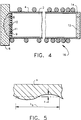
- the ultrasonic parametric amplifier in accordance with a preferred embodiment of the invention comprises a rigid duct 4 filled with viscous fluid 2.
- Duct 4 has a periodic wall with an inner surface which is axisymmetric.
- the fluid 2 in the metal duct 4 (not shown to scale) is excited at the design frequency by a driving signal imposed on a transducer 6 by external signal generator electronics (not shown).
- the transducer produces ultrasonic energy which is focused by lens 8.
- This focused ultrasonic energy excites a metal diaphragm 9 coupled to an exciter pin 10 located at the focus of lens 8.
- the diaphragm produces an ultrasonic compressional wave with wave number k which enters the waveguide through pin 10 and propagates axially in the fluid.
- the traveling wave is a continuous wave, or "burst", which travels along the duct 4 and radiates out a window 12 which closes the opposite end of the duct and is secured to the inner surface of the duct wall by bonding material 14.
- the energy radiated at the exit window 12 is a burst of essentially plane waves, which can be concentrated by a small lens (not shown) near the output, if required by the application.
- the window material should be made of a material with acoustic impedance close to that of the fluid ( e . g ., LUCITE for water).
- the duct wall can be either rigid or flexible, but is most useful when made of metal, a preferred material.
- the duct walls are designed to be relatively rigid, either by thickness or by the stiffening effect of a metal-jacketed variable-pitch heater coil 16.
- the wavelength ⁇ s of the surface fluctuations is digitally controlled to the proper value for the frequency of ultrasound to be amplified. This is the means of "tuning" the amplifier, or selecting the sonic wavelength and frequency so that the amplitude will grow as the ultrasonic wave propagates. Actually, a narrow band of frequencies will be amplified, but the bandwidth can be made very small by design.
- p 0, ⁇ 0, T 0 are the bulk fluid pressure, density and absolute temperature, respectively
- h is the heat transfer coefficient for the shell wall and the fluid
- c is the sonic velocity in the fluid
- c v is the specific heat at constant volume for the fluid
- T is the local absolute temperature of the fluid
- ⁇ ( z ) is the wall absolute temperature profile.
- the required heat addition is proportional to the fluid density, the duct radius and the frequency squared.
- the fluid temperature enters the equation via the sonic velocity and the heat transfer coefficient, which are functions of the fluid used.
- the coefficient ⁇ 0> rms can be computed numerically from the Mathieu functions and is independent of fluid or duct properties. Therefore, the heat addition is essentially exponential with distance in the preferred configuration, although it may be possible to use piecewise linear profiles and/or other heat addition functions. All of these variations are included within the scope of the claimed invention.
- the fluid temperature varies with axial distance like: T ( ⁇ y >4) T 0 ⁇ 1 - B ⁇ e sy ; ⁇ >> s Therefore, the fluid temperature variation can be minimized by designing the thermal properties of the system so that ⁇ is large and B is small. Although sub-optimal, this is sufficient in many practical situations.
- amplification can occur for waves propagating in either direction when the walls are uniformly heated. This is because the characteristic exponent exhibits solutions with negative real part and positive imaginary part, as discussed above.
- the two-way amplification that results is limited by the need for constant wall temperature, which eventually inhibits intensity growth in both directions of propagation.
- For one-way propagation unlimited growth is possible, in principle, using the proper wall temperature profile. Reflections would not grow substantially, in this case, as they would in the case of uniform wall temperature.
- the duct wall is chosen to be thick enough ( ⁇ 2-4 mm) that it is essentially rigid for purposes of wave propagation.
Landscapes
- Physics & Mathematics (AREA)
- Engineering & Computer Science (AREA)
- Acoustics & Sound (AREA)
- Multimedia (AREA)
- Investigating Or Analyzing Materials By The Use Of Ultrasonic Waves (AREA)
Applications Claiming Priority (2)
| Application Number | Priority Date | Filing Date | Title |
|---|---|---|---|
| US966474 | 1992-10-26 | ||
| US07/966,474 US5435186A (en) | 1992-10-26 | 1992-10-26 | Ultrasonic parametric amplifier |
Publications (2)
| Publication Number | Publication Date |
|---|---|
| EP0595572A2 true EP0595572A2 (de) | 1994-05-04 |
| EP0595572A3 EP0595572A3 (de) | 1995-07-12 |
Family
ID=25511461
Family Applications (1)
| Application Number | Title | Priority Date | Filing Date |
|---|---|---|---|
| EP93308472A Withdrawn EP0595572A3 (de) | 1992-10-26 | 1993-10-25 | Parametrisches Ultraschallverstärker. |
Country Status (4)
| Country | Link |
|---|---|
| US (1) | US5435186A (de) |
| EP (1) | EP0595572A3 (de) |
| JP (1) | JPH06229989A (de) |
| TW (1) | TW241338B (de) |
Families Citing this family (4)
| Publication number | Priority date | Publication date | Assignee | Title |
|---|---|---|---|---|
| JP2006005631A (ja) * | 2004-06-17 | 2006-01-05 | Alps Electric Co Ltd | 音波増幅器 |
| US9918495B2 (en) | 2014-02-28 | 2018-03-20 | Rai Strategic Holdings, Inc. | Atomizer for an aerosol delivery device and related input, aerosol production assembly, cartridge, and method |
| US9277770B2 (en) | 2013-03-14 | 2016-03-08 | R. J. Reynolds Tobacco Company | Atomizer for an aerosol delivery device formed from a continuously extending wire and related input, cartridge, and method |
| CN120068318B (zh) * | 2025-04-29 | 2025-06-27 | 融通航空发动机科技有限公司 | 一种过渡段流道壁型线参数化设计方法 |
Family Cites Families (11)
| Publication number | Priority date | Publication date | Assignee | Title |
|---|---|---|---|---|
| US3145312A (en) * | 1959-04-13 | 1964-08-18 | Libbey Owens Ford Glass Co | High frequency sonic transducers |
| US3233183A (en) * | 1962-09-06 | 1966-02-01 | Calvin F Quate | Parametric amplifier using an acoustical wave to passively couple two electromagnetic waves having different velocities of propagation |
| US3568080A (en) * | 1969-07-23 | 1971-03-02 | Ronald R Troutman | Self-transducing ultrasonic amplifier |
| US3634774A (en) * | 1970-07-15 | 1972-01-11 | Us Air Force | Acoustic surface wave parametric amplifier |
| US3873858A (en) * | 1972-05-23 | 1975-03-25 | Massachusetts Inst Technology | Acoustic surface wave phase shifter |
| US4025876A (en) * | 1975-09-12 | 1977-05-24 | Nasa | Distributed feedback acoustic surface wave oscillator |
| DE3331249C2 (de) * | 1982-09-01 | 1995-11-09 | Clarion Co Ltd | Parametrischer Verstärker |
| US4662215A (en) * | 1984-08-20 | 1987-05-05 | Aluminum Company Of America | Apparatus and method for ultrasonic detection of inclusions in a molten body |
| EP0309713A3 (de) * | 1987-09-29 | 1989-12-27 | Siemens Aktiengesellschaft | Verstärkender Oberflächenwellen-Empfänger |
| EP0309714A3 (de) * | 1987-09-29 | 1990-08-08 | Siemens Aktiengesellschaft | Frequenzverdoppelnder, verstärkender Oberflächenwellen-Empfänger |
| JPH02281185A (ja) * | 1989-04-21 | 1990-11-16 | Yasuyuki Sugano | 常温核融合超音波促進法 |
-
1992
- 1992-10-26 US US07/966,474 patent/US5435186A/en not_active Expired - Fee Related
-
1993
- 1993-05-11 TW TW082103677A patent/TW241338B/zh active
- 1993-10-25 JP JP5265322A patent/JPH06229989A/ja not_active Withdrawn
- 1993-10-25 EP EP93308472A patent/EP0595572A3/de not_active Withdrawn
Also Published As
| Publication number | Publication date |
|---|---|
| JPH06229989A (ja) | 1994-08-19 |
| TW241338B (de) | 1995-02-21 |
| US5435186A (en) | 1995-07-25 |
| EP0595572A3 (de) | 1995-07-12 |
Similar Documents
| Publication | Publication Date | Title |
|---|---|---|
| US5289436A (en) | Ultrasonic waveguide | |
| US4246784A (en) | Passive remote temperature sensor system | |
| US4783997A (en) | Ultrasonic transducers for high temperature applications | |
| US9869659B2 (en) | Acoustic sensor | |
| Marston | Acoustic beam scattering and excitation of sphere resonance: Bessel beam example | |
| JPS6312537B2 (de) | ||
| Ramadan et al. | Experimental investigation of the influence of natural convection and end-effects on Rayleigh streaming in a thermoacoustic engine | |
| US5435186A (en) | Ultrasonic parametric amplifier | |
| Olivier et al. | Asymmetric transmission and coherent perfect absorption in a periodic array of thermoacoustic cells | |
| Zaitsev et al. | Determination of the acoustic wave velocity and attenuation in liquids with different acoustic impedances using an acoustic interferometer | |
| US7185547B2 (en) | Extreme temperature clamp-on ultrasonic flowmeter transducer | |
| JPH06217395A (ja) | 単色超音波変換器 | |
| Suñol et al. | Performance assessment of ultrasonic waves for bubble control in cryogenic fuel tanks | |
| Apfel | Acoustic thermometry | |
| AU667408B2 (en) | Apparatus for determining physical properties of fluids | |
| Poignand et al. | Parity-time symmetric system based on the thermoacoustic effect | |
| Kumar et al. | Experimental study of ultrasonic wave propagation in a long waveguide sensor for fluid-level sensing | |
| GB2071297A (en) | Controlled-temperature measuring cell for photo-acoustic spectroscopy | |
| US3087138A (en) | Apparatus for measuring sound speed and attenuation characteristics in liquid media | |
| US20100052479A1 (en) | Remote ultrasonic transducer system | |
| JP2003139591A (ja) | 超音波流量計 | |
| Garrett et al. | Resonant nonlinear mode conversion in He II | |
| Uehara et al. | Two-layer calorimeter with thermally insulating separator for measuring ultrasonic power | |
| Valabhoju et al. | Ultrasonic waveguide with enhanced ultrasonic reflectors for developing temperature measurement sensors | |
| Chivers | Fundamentals of ultrasonic propagation |
Legal Events
| Date | Code | Title | Description |
|---|---|---|---|
| PUAI | Public reference made under article 153(3) epc to a published international application that has entered the european phase |
Free format text: ORIGINAL CODE: 0009012 |
|
| AK | Designated contracting states |
Kind code of ref document: A2 Designated state(s): CH DE ES LI |
|
| PUAL | Search report despatched |
Free format text: ORIGINAL CODE: 0009013 |
|
| AK | Designated contracting states |
Kind code of ref document: A3 Designated state(s): CH DE ES LI |
|
| 17P | Request for examination filed |
Effective date: 19960112 |
|
| 18W | Application withdrawn |
Withdrawal date: 19960812 |