EP0595763A2 - Lame de coupe à haute résistance d'usure et procédé pour sa fabrication - Google Patents
Lame de coupe à haute résistance d'usure et procédé pour sa fabrication Download PDFInfo
- Publication number
- EP0595763A2 EP0595763A2 EP93810641A EP93810641A EP0595763A2 EP 0595763 A2 EP0595763 A2 EP 0595763A2 EP 93810641 A EP93810641 A EP 93810641A EP 93810641 A EP93810641 A EP 93810641A EP 0595763 A2 EP0595763 A2 EP 0595763A2
- Authority
- EP
- European Patent Office
- Prior art keywords
- carrier
- knife
- hard material
- cutting bar
- bar according
- Prior art date
- Legal status (The legal status is an assumption and is not a legal conclusion. Google has not performed a legal analysis and makes no representation as to the accuracy of the status listed.)
- Granted
Links
Images

Classifications
-
- B—PERFORMING OPERATIONS; TRANSPORTING
- B02—CRUSHING, PULVERISING, OR DISINTEGRATING; PREPARATORY TREATMENT OF GRAIN FOR MILLING
- B02C—CRUSHING, PULVERISING, OR DISINTEGRATING IN GENERAL; MILLING GRAIN
- B02C18/00—Disintegrating by knives or other cutting or tearing members which chop material into fragments
- B02C18/06—Disintegrating by knives or other cutting or tearing members which chop material into fragments with rotating knives
- B02C18/16—Details
- B02C18/18—Knives; Mountings thereof
- B02C2018/188—Stationary counter-knives; Mountings thereof
Definitions
- the present invention relates to cutting strips, which are preferably used in cooperation with cutting rotors, inter alia for the production of granules, and to a method for producing such cutting strips.
- Knives which consist entirely of hard metal or of a support made of steel and a knife made of hard metal soldered thereon. This solder connection is problematic in itself, since hard metal is poorly wetted by the common soldering materials, but the reject rate is still within acceptable limits. However, the relatively soft steel beam is subject to a high degree of abrasion, which limits the life of such cutting strips.
- Both materials, PCD and CBN, are commercially available as a layer structure consisting of a carrier, which in the context of the present invention consists of a hard metal and is called a knife carrier, and an associated layer or coating of a hard material. In principle, strips made of this material can be used as knives for cutting strips.
- the knife carrier is chemically changed when the hard material layer is applied, specifically the carrier is enriched with carbon, and it is also not always possible to select the optimal materials for the carrier for the respective application.
- the hard-coated knives such as the hard-metal knives previously, are to be soldered onto another carrier in order to obtain a cutting bar.
- the hard-coated knives can be soldered onto a carrier even more poorly than hard-metal knives. This is primarily attributed to the above-mentioned carbon enrichment in the knife holder.
- the knife carrier material is subject to wear where it comes to the surface of the cutting bar, and all the more because the knife carrier material loses part of its wear resistance during the application of the hard material layer.
- Such a cutting bar is specified in claim 1.
- the further claims include preferred designs, methods for producing the cutting bar according to the invention and types of use.
- the cutting bar according to the invention consists of a carrier which preferably consists of a highly wear-resistant hard metal and onto which a knife coated with a hard material is soldered.
- the contact surface of the knife carrier is shaped in such a way that the carrier closes with the hard material at most with a functionally negligible joint on the surfaces exposed to the material to be processed.
- connection point between the cutting edge support and the knife is preferably made by soldering.
- the surfaces to be soldered are provided with a solder-friendly metal layer. This is preferably done according to the method described in the applicant's Swiss patent specification CH-649 089, which is hereby incorporated into the description.
- a metal layer of a few micrometers to a few 100 micrometers is applied and alloyed into the surface of the hard metal at high temperature, which not only creates a solder-friendly surface, but also fills up existing surface irregularities (voids) with the metal.
- Nickel is particularly suitable for surface treatment for price reasons.
- Other metals are possible, e.g. B. silver, copper or cobalt.
- One embodiment of the invention consists of the hard material knife and the carrier, the carrier having the necessary fastening devices in order to be able to fasten the bar, for example in a cutting machine.
- a preferred embodiment of the invention consists in fastening the carrier on a holder by means of a releasable connection technique. This makes it possible to replace worn or damaged sections of the cutting edge.
- the holder can also be made in a less wear-resistant material, which on the other hand, for example, an easier attachment of fasteners such.
- an undercut groove ie a groove that widens towards the bottom, is incorporated into the knife carrier, into which suitable slot nuts can be inserted as anchors.
- the sliding blocks are connected to the carrier using suitable fastening elements. You can e.g. B. z. B. have holes with an internal thread, whereby they by means of screws which are inserted through the carrier, can be used and fix the hard material knife on the carrier.
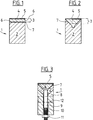
- the known hard material cutting strip 1 shown in FIG. 1 consists of a carrier 2 onto which the hard material knife 3 is soldered.
- the hard material knife consists of the knife carrier 4, on which the hard material layer 5 is applied.
- the hard material 5 is preferably polycrystalline diamond (PCD) or cubic boron nitride (CBN).
- the exposed flanks 6 of the knife carrier 4 are exposed to wear in the conventional cutting bar 1 (FIG. 1). After a short time, the hard material layer 5 is undermined, which leads to damage to the cutting edge. 2, this problem can be solved according to the invention in that the knife 3 is inserted into a V-shaped groove in the carrier 2, for which purpose the flanks 6 of the knife carrier 4 are removed in mirror image to the shape of the groove. The resulting bevels preferably extend without borders to the hard material layer 5. After insertion, the sides of the carrier 2 can be ground to the mass of the knife 3.
- the second problem area is the soldered connection 7 between the knife carrier 4 and the carrier 2.
- the knife carrier 4 has an excess of carbon which on the one hand worsens the mechanical properties of the carrier material 4 and on the other hand also reduces the solderability. Even or especially when inserting the knife 3 into a V-groove, an insufficient reliability of the connection between the carrier 2 and the knife 3 was found in practice. Since with the V-groove the forces occurring during cutting are converted to a greater extent into shear stresses, with the V-groove the quality of the connection between carrier 2 and knife 3 is of increased importance.
- the surface 7 of the knife carrier 4 can be metallized at high temperatures and thus made solder-friendly, preferably according to the method as described in CH-649 098. Contrary to the expectation that the hard material layer would be attacked at the temperatures necessary for the metallization and, in the worst case, decomposed, no such effects were surprisingly observed to any appreciable extent if the metallization was carried out in an inert, at least oxygen-free atmosphere or in a vacuum.
- the reliable solder connection achieved in this way allows the advantages of the V connection to be exploited.
- the knife according to the invention achieves a long service life since highly wear-resistant supports 2 can be used, and can be used in high yield. The risk of the knife detaching from the carrier 2 during operation is reduced to an insignificant value by the high quality solder connection. It is also advantageous that the cutting bar according to the invention can have two cutting edges, as a result of which the service life is increased again. With the knife according to the invention, tool life of 1 2nd a per cutting edge, after which the second cutting edge can be used by turning the bar.
- two fastening elements such as holes, inserted threaded bushings, etc., are present on the carrier in order to fasten the arrangement at the place of use.
- the cutting bar 1 is connected to a holder 8 which has the fastening elements mentioned above. Since the holder 8 is no longer exposed to the effects of abrasion to the extent that the cutting bar 1, other suitable materials can also be used in addition to hard metal, such as, for. B. stainless steel, in which the fasteners are easier to attach.
- 3 shows transverse holes 12 as an example.
- connection between holder 8 and carrier 2 is preferably releasable, for. B. by means of screw elements.
- a preferred solution is to provide at least one bore in the carrier 2, into which a threaded rod 9 is inserted and permanently attached, e.g. B. is soldered.
- a corresponding bore 10 is provided in the holder 8, through which the threaded rod 9 projects.
- a nut 11 is screwed onto the threaded rod 9 and tightened.
- Another version uses a screw instead of the threaded rod, which is screwed into a threaded bushing inserted in the carrier 2.
- an undercut groove 15 is machined into the carrier 4 in the longitudinal direction of the hard material knife 3.
- slot nuts 16 can be used, into which a thread is cut.
- a screw 17 is passed from below through a bore 18 in the carrier 2 and screwed into a slot nut 16, as a result of which the hard material knife 3 is fixed on the carrier 2 in the V-groove.
- At least 2 slot nuts are preferably provided for fastening per hard material knife.
- the bore 18 is preferably designed such that the head of the screw 17 is countersunk in the carrier. By choosing the depth this recess can also be adapted to the length of the screws 17 available.
- the groove 15 is preferably produced in the knife carrier 4 by means of erosion. This is simply done in one step with the production of the oblique flanks of the knife carrier 4.
- the cutting bar can be attached to an additional holder 8 analogously to the embodiment according to FIG. 3.
Landscapes
- Engineering & Computer Science (AREA)
- Food Science & Technology (AREA)
- Forging (AREA)
- Knives (AREA)
- Nonmetal Cutting Devices (AREA)
- Excavating Of Shafts Or Tunnels (AREA)
- Crushing And Pulverization Processes (AREA)
- Wire Processing (AREA)
- Drilling Tools (AREA)
Applications Claiming Priority (2)
| Application Number | Priority Date | Filing Date | Title |
|---|---|---|---|
| CH332392 | 1992-10-26 | ||
| CH3323/92 | 1992-10-26 |
Publications (3)
| Publication Number | Publication Date |
|---|---|
| EP0595763A2 true EP0595763A2 (fr) | 1994-05-04 |
| EP0595763A3 EP0595763A3 (en) | 1994-06-08 |
| EP0595763B1 EP0595763B1 (fr) | 1996-08-14 |
Family
ID=4253494
Family Applications (1)
| Application Number | Title | Priority Date | Filing Date |
|---|---|---|---|
| EP93810641A Expired - Lifetime EP0595763B1 (fr) | 1992-10-26 | 1993-09-09 | Lame de coupe à haute résistance d'usure et procédé pour sa fabrication |
Country Status (3)
| Country | Link |
|---|---|
| EP (1) | EP0595763B1 (fr) |
| AT (1) | ATE141189T1 (fr) |
| DE (1) | DE59303432D1 (fr) |
Cited By (2)
| Publication number | Priority date | Publication date | Assignee | Title |
|---|---|---|---|---|
| AT513376B1 (de) * | 2012-11-12 | 2014-04-15 | Econ Gmbh | Granuliermesser für einen Messerkopf einer Granuliervorrichtung |
| WO2015193249A1 (fr) * | 2014-06-18 | 2015-12-23 | Betek Gmbh & Co. Kg | Contre-lame |
Family Cites Families (4)
| Publication number | Priority date | Publication date | Assignee | Title |
|---|---|---|---|---|
| US2857111A (en) * | 1955-01-21 | 1958-10-21 | Unipulver Ltd | Rotor blades and blade mounting means for grinding mills |
| DE3108954C2 (de) * | 1981-03-10 | 1986-07-24 | Michael Dr.-Ing. 3100 Celle Kaiser | Messer und Verfahren zu seiner Herstellung |
| DE3927106A1 (de) * | 1989-08-17 | 1991-02-21 | Schober Werkzeug & Maschbau | Schneidwalze oder stanzzylinder und verfahren zum herstellen von solchen |
| EP0430872B1 (fr) * | 1989-11-22 | 1995-04-05 | Balzers Aktiengesellschaft | Outil ou instrument ayant un revêtement dur résistant à l'usure pour l'usinage de matériaux organiques |
-
1993
- 1993-09-09 AT AT93810641T patent/ATE141189T1/de active
- 1993-09-09 EP EP93810641A patent/EP0595763B1/fr not_active Expired - Lifetime
- 1993-09-09 DE DE59303432T patent/DE59303432D1/de not_active Expired - Fee Related
Cited By (4)
| Publication number | Priority date | Publication date | Assignee | Title |
|---|---|---|---|---|
| AT513376B1 (de) * | 2012-11-12 | 2014-04-15 | Econ Gmbh | Granuliermesser für einen Messerkopf einer Granuliervorrichtung |
| AT513376A4 (de) * | 2012-11-12 | 2014-04-15 | Econ Gmbh | Granuliermesser für einen Messerkopf einer Granuliervorrichtung |
| EP2730384B1 (fr) | 2012-11-12 | 2016-09-28 | ECON GmbH | Couteau de granulation pour une tête porte lame d'un dispositif de granulation |
| WO2015193249A1 (fr) * | 2014-06-18 | 2015-12-23 | Betek Gmbh & Co. Kg | Contre-lame |
Also Published As
| Publication number | Publication date |
|---|---|
| EP0595763B1 (fr) | 1996-08-14 |
| ATE141189T1 (de) | 1996-08-15 |
| DE59303432D1 (de) | 1996-09-19 |
| EP0595763A3 (en) | 1994-06-08 |
Similar Documents
| Publication | Publication Date | Title |
|---|---|---|
| DE69406046T2 (de) | Sägekettenschneidglied | |
| DE68918369T2 (de) | Bohrmeissel mit Zementcarbideinsätzen. | |
| EP0715055B1 (fr) | Outil avec corps de base et élément de coupe | |
| DE19903037C2 (de) | Schneidwerkzeug mit Mitteln zur Spankontrolle | |
| DE2848976A1 (de) | Vorrichtung zum maschinellen behandeln der oberflaeche von langhoelzern | |
| DE2619210A1 (de) | Stabilisiervorrichtung fuer einen bohrstrang | |
| EP1023961B1 (fr) | Outil de coupe | |
| EP1425125B1 (fr) | Outil de coupe | |
| DE69503537T2 (de) | CVD Diamant Schneidwerkzeuge | |
| DE19625509A1 (de) | Werkzeugkomponente | |
| EP0715919B1 (fr) | Procédé et lame de scie pour le sciage des pièces en acier | |
| AT9431U1 (de) | Schneidplatte | |
| EP0595763B1 (fr) | Lame de coupe à haute résistance d'usure et procédé pour sa fabrication | |
| EP2039482B1 (fr) | Couteau à segment | |
| DE68917342T2 (de) | Werkzeuge mit Einsatzzähnen. | |
| EP0099004A1 (fr) | Matrice de découpe, en particulier pour la découpe de contours et son procédé de fabrication | |
| CH665790A5 (de) | Bohrer. | |
| DE3108954A1 (de) | Messer | |
| EP3993938B1 (fr) | Outil d'usinage par enlèvement de copeaux à dents asymétriques munies de particules de coupe | |
| DE925142C (de) | Schneidwerkzeug | |
| DE69610729T2 (de) | Schneideinsatz für Fräsbohrmeissel | |
| AT505198B1 (de) | Schneidwerkzeug | |
| DE3531767C2 (fr) | ||
| DE1477299A1 (de) | Schneidwerkzeug zum Bearbeiten von Metall | |
| EP0947268B1 (fr) | Plaquette de coupe pour outils d'usinage |
Legal Events
| Date | Code | Title | Description |
|---|---|---|---|
| PUAI | Public reference made under article 153(3) epc to a published international application that has entered the european phase |
Free format text: ORIGINAL CODE: 0009012 |
|
| PUAL | Search report despatched |
Free format text: ORIGINAL CODE: 0009013 |
|
| AK | Designated contracting states |
Kind code of ref document: A2 Designated state(s): AT BE CH DE DK ES FR GB GR IE IT LI LU MC NL PT SE |
|
| AK | Designated contracting states |
Kind code of ref document: A3 Designated state(s): AT BE CH DE DK ES FR GB GR IE IT LI LU MC NL PT SE |
|
| RBV | Designated contracting states (corrected) |
Designated state(s): AT CH DE FR GB LI NL |
|
| 17P | Request for examination filed |
Effective date: 19940722 |
|
| GRAG | Despatch of communication of intention to grant |
Free format text: ORIGINAL CODE: EPIDOS AGRA |
|
| GRAH | Despatch of communication of intention to grant a patent |
Free format text: ORIGINAL CODE: EPIDOS IGRA |
|
| 17Q | First examination report despatched |
Effective date: 19960214 |
|
| GRAH | Despatch of communication of intention to grant a patent |
Free format text: ORIGINAL CODE: EPIDOS IGRA |
|
| GRAA | (expected) grant |
Free format text: ORIGINAL CODE: 0009210 |
|
| AK | Designated contracting states |
Kind code of ref document: B1 Designated state(s): AT CH DE FR GB LI NL |
|
| PG25 | Lapsed in a contracting state [announced via postgrant information from national office to epo] |
Ref country code: GB Effective date: 19960814 Ref country code: FR Effective date: 19960814 |
|
| REF | Corresponds to: |
Ref document number: 141189 Country of ref document: AT Date of ref document: 19960815 Kind code of ref document: T |
|
| REG | Reference to a national code |
Ref country code: CH Ref legal event code: NV Representative=s name: AMMANN PATENTANWAELTE AG BERN |
|
| PG25 | Lapsed in a contracting state [announced via postgrant information from national office to epo] |
Ref country code: AT Effective date: 19960909 |
|
| REF | Corresponds to: |
Ref document number: 59303432 Country of ref document: DE Date of ref document: 19960919 |
|
| EN | Fr: translation not filed | ||
| GBV | Gb: ep patent (uk) treated as always having been void in accordance with gb section 77(7)/1977 [no translation filed] |
Effective date: 19960814 |
|
| PLBE | No opposition filed within time limit |
Free format text: ORIGINAL CODE: 0009261 |
|
| STAA | Information on the status of an ep patent application or granted ep patent |
Free format text: STATUS: NO OPPOSITION FILED WITHIN TIME LIMIT |
|
| 26N | No opposition filed | ||
| PGFP | Annual fee paid to national office [announced via postgrant information from national office to epo] |
Ref country code: CH Payment date: 19970924 Year of fee payment: 5 |
|
| PGFP | Annual fee paid to national office [announced via postgrant information from national office to epo] |
Ref country code: NL Payment date: 19970930 Year of fee payment: 5 |
|
| PGFP | Annual fee paid to national office [announced via postgrant information from national office to epo] |
Ref country code: DE Payment date: 19971119 Year of fee payment: 5 |
|
| PG25 | Lapsed in a contracting state [announced via postgrant information from national office to epo] |
Ref country code: LI Free format text: LAPSE BECAUSE OF NON-PAYMENT OF DUE FEES Effective date: 19980930 Ref country code: CH Free format text: LAPSE BECAUSE OF NON-PAYMENT OF DUE FEES Effective date: 19980930 |
|
| PG25 | Lapsed in a contracting state [announced via postgrant information from national office to epo] |
Ref country code: NL Free format text: LAPSE BECAUSE OF NON-PAYMENT OF DUE FEES Effective date: 19990401 |
|
| REG | Reference to a national code |
Ref country code: CH Ref legal event code: PL |
|
| NLV4 | Nl: lapsed or anulled due to non-payment of the annual fee |
Effective date: 19990401 |
|
| PG25 | Lapsed in a contracting state [announced via postgrant information from national office to epo] |
Ref country code: DE Free format text: LAPSE BECAUSE OF NON-PAYMENT OF DUE FEES Effective date: 19990701 |