EP0595900B1 - Bett mit mehreren stellungen - Google Patents
Bett mit mehreren stellungen Download PDFInfo
- Publication number
- EP0595900B1 EP0595900B1 EP92915680A EP92915680A EP0595900B1 EP 0595900 B1 EP0595900 B1 EP 0595900B1 EP 92915680 A EP92915680 A EP 92915680A EP 92915680 A EP92915680 A EP 92915680A EP 0595900 B1 EP0595900 B1 EP 0595900B1
- Authority
- EP
- European Patent Office
- Prior art keywords
- bed
- mounting means
- bed according
- frame
- pillars
- Prior art date
- Legal status (The legal status is an assumption and is not a legal conclusion. Google has not performed a legal analysis and makes no representation as to the accuracy of the status listed.)
- Expired - Lifetime
Links
- 230000001419 dependent effect Effects 0.000 claims 1
- 210000001217 buttock Anatomy 0.000 description 6
- 210000000689 upper leg Anatomy 0.000 description 6
- 244000309466 calf Species 0.000 description 5
- 229910000831 Steel Inorganic materials 0.000 description 3
- 238000010276 construction Methods 0.000 description 3
- 230000000694 effects Effects 0.000 description 3
- 239000010959 steel Substances 0.000 description 3
- 230000007257 malfunction Effects 0.000 description 2
- 238000012544 monitoring process Methods 0.000 description 2
- 208000004210 Pressure Ulcer Diseases 0.000 description 1
- 230000007423 decrease Effects 0.000 description 1
Images


Classifications
-
- A—HUMAN NECESSITIES
- A61—MEDICAL OR VETERINARY SCIENCE; HYGIENE
- A61G—TRANSPORT, PERSONAL CONVEYANCES, OR ACCOMMODATION SPECIALLY ADAPTED FOR PATIENTS OR DISABLED PERSONS; OPERATING TABLES OR CHAIRS; CHAIRS FOR DENTISTRY; FUNERAL DEVICES
- A61G7/00—Beds specially adapted for nursing; Devices for lifting patients or disabled persons
- A61G7/002—Beds specially adapted for nursing; Devices for lifting patients or disabled persons having adjustable mattress frame
- A61G7/012—Beds specially adapted for nursing; Devices for lifting patients or disabled persons having adjustable mattress frame raising or lowering of the whole mattress frame
Definitions
- This invention relates to a multi-positional bed.
- Such beds are used in hospitals, and are also used in domestic situations and in homes for the elderly and infirm, where it is necessary to have a bed which can be adjusted to suit a particular individual or which can successively occupy a number of different positions, for example in order to reduce the risk of bed sores.
- a supporting surface which normally consists of three or four sections pivotally connected to one another.
- these are, starting from the head end of the bed, a back section, a buttocks section, a thigh section and a calf section.
- the thigh and calf sections are replaced by a single section, or the buttocks section is omitted.
- the sections are connected to one another in such a way as to allow pivotal movement between adjacent sections about parallel axes transverse to the length of the bed.
- Such beds also normally have provision for the whole supporting surface to be moved vertically between high and low positions. The user normally gets into the bed with the supporting section in its low position (this is particularly convenient when the user is in a wheelchair), and the supporting surface can thereafter be raised so as to make it easier for those attending the user.
- Some beds also allow the whole supporting surface to be tilted about the transverse and/or longitudinal axis of the bed. However, when these additional movements are incorporated the resultant mechanism tends to be highly complex and therefore very expensive. It is an object of the present invention to provide a bed in which all the types of adjustment referred to above are present, but which does not require a mechanism of great complexity.
- GB-A-2209464 describes multi-positional bed which comprises a pair of pillars at one end thereof, one at or near each side of the bed, a pillar at the opposite end of the bed, a user-supporting frame and respective mounting means for mounting the frame to each of the pillars, each mounting means being arranged to move lengthwise of the respective pillar independently of the movement of the other mounting means and having degrees of freedom sufficient to permit the frame to pivot both about its longitudinal axis and about an axis transverse thereto.
- a multi-positional bed of the type just defined characterised in that there is a single pillar at said opposite end, situated substantially on the longitudinal centre line of the bed.
- each of the mounting means comprises at least one universal joint, for example a ball joint.
- the end of the bed at which the pair of pillars is situated may be the head end, with the single pillar at the foot end, or the pair of pillars may be at the foot end, with the single pillar at the head end.
- the mounting means are preferably moved by respective electric motors, and these motors are preferably controlled by a controller which permits pre-programmed and/or programmable control and direct operator control.
- the user-supporting frame preferably comprises three or four sections pivotally connected to one another as in a conventional multi-positional bed, and pivotal movement of the sections with respect to one another is preferably effected by further electric motors which are under the control of the same controller as that already mentioned.
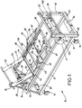
- the illustrated bed 10 comprises a lower frame 12 supported on four wheels 14. At the foot end of the bed there is a pair of upstanding pillars 16 and 18 connected intermediate their ends by a cross-brace 20 and adjacent their upper ends by a top brace 22. At the head end of the bed there is a single upstanding pillar 24 which is situated substantially on the longitudinal centre line of the bed. The pillar 24 is connected at its lower end to the lower frame 12, and is connected to the adjacent corners of the lower frame by diagonal braces 26 and 28.
- the pillars 16, 18 and 24 are substantially identical to one another in construction. The details of that construction will be referred to further below.
- the bed further comprises an upper frame 30.
- the corners of the frame 30 are connected to the pillars 16 and 18 by respective mounting means 32 and 34 and at the head of the bed the frame 30 is connected at a point midway between its corners to the pillar 24 by a mounting means 36.
- Each of the mounting means 32, 34 and 36 is movable longitudinally with respect to its respective pillar to enable the adjacent portion of the upper frame 30 to move vertically upwards or downwards.
- the longer sides of the frame 30 each have a U-section member 31 secured thereto, with the open sides of the U's facing one another.
- An inner frame 58 is mounted for movement longitudinally with respect to the frame 30, by means of wheels (not visible in the drawings) which are carried by the frame 58 and which run in the U-section members 31.
- the inner frame 58 has connected thereto the necessary members to define a plurality of user-supporting sections.
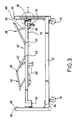
- there are four such sections which, as can be seen most clearly in Figure 3, consist of a back section 38, a buttocks section 40, a thigh section 42 and a calf section 44.
- the buttocks section 40 is fixed with respect to the frame 58.
- the head section 38 is pivotally connected to the buttocks section 40 at pivot points 46
- the thigh section 42 is pivotally connected to the buttocks section 40 at pivot points 48.
- the calf section 44 is pivotally connected to the thigh section 42 at pivot points 50.
- the back section 38 has a transverse member 52 and a pair of struts 54 connect the member 52 with struts 56 which extend downwardly from the upper frame 30.
- the transverse member is pivotally connected at its ends to the back section 38, and the struts 54 are pivotally connected at their lower ends with the struts 56.
- the pivot points 46 and 48 are located in the inner frame 58.
- the inner frame 58 also carries pivots for the lower ends of two elbow-like linkages 60 each of which consists of two struts pivotally connected to one another, with the distal end of the upper strut being pivotally connected to the thigh section 42.
- the inner frame 58 further carries the pivot points for a pair of struts 62 which are each connected at their opposite ends to the calf section 44. Pivotal movement of the sections 38, 42 and 44 is effected by means of motors 64 and 66 which cause respective screw threaded shafts 68 and 70 to rotate.
- the shafts 68 and 70 are received in respective internally threaded blocks 72 and 74.
- the block 72 is mounted between a pair of arms which are fast with a cross member 78 with extends between the linkages 60.
- the block 74 is secured to a cross member 80, the ends of which are secured to the frame 58.
- the arrangement and operation of the four user-supporting sections is basically conventional, except for the fact that the control for the motors 64 and 66 is integrated with the pre-programmed and/or programmable control of the movement of the frame 30. It is to be understood that the particular four-section arrangement within the frame 30 could be replaced by any other desired arrangement, which would not necessarily have four sections.
- each of the pillars 16, 18 and 24 there is mounted a respective electric motor 82.
- the motors 82, and also the motors 64 and 66, are preferably low voltage DC motors, for example 12 volt motors, to which power is supplied by a 12 volt, rechargeable battery.
- the battery and the charger therefor are indicated diagrammatically at 84 in Figures 1 to 3.
- the charger In use, the charger is normally kept permanently connected to a mains supply, to keep the battery fully charged. If, however, the charger has to be disconnected from the mains for any reason, or if the mains supply fails, the motors can continue to operate for some time before the battery becomes fully discharged.
- Each motor 82 is connected by appropriate gearing (not shown) to the lower end of a threaded rod which extends longitudinally within the adjacent pillar and protrudes a short distance above the top of the pillar.
- Each of the protruding ends meshes with a gear 86 which rotates about a horizontal axis when the respective rod rotates about its vertical axis. Rotation of the gears 86 is detected by suitable monitoring means, and signals from these monitoring means are fed to the controller to indicate the extent to which the rod has rotated in either sense.
- the rods just mentioned are denoted by reference numeral 88, and Figure 6 shows the way in which the rod 88 is disposed in the case of pillar 18.
- the other two rods 88 operate in a similar fashion.
- the pillar 18 has two hollow portions, and within the larger of them there is slidably mounted a rectangular member 90 which has an internally threaded bore 92 in which the rod 88 is threadedly received.
- the pillar has a longitudinal slot 94, and the rectangular member 90 is integral with a U-shaped member 96 via a bridge member 98 which extends through the slot 94.
- the members 90, 96 and 98 are referred to below collectively as the block 100.
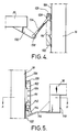
- a further block 102 is secured within the U-shaped member 96 by fasteners 104, the block 102 extending both below and above the U-shaped member 96, as can be seen in Figure 5.
- a flexible steel strip 106 is secured to the pillar 18 adjacent the upper and lower ends of the pillar, and serves to cover the aperture 94 above and below where the aperture is covered by the blocks 100 and 102.
- the steel strip is selected to have an inherent tendency to curl away from the pillar at its upper and lower ends, so that by clamping the steel strip firmly to the pillar at those ends it is ensured that the strip remains tightly over the aperture at all points.
- a corresponding arrangement is provided for each of the other pillars, 16 and 24.
- the block 100 has secured thereto a short shaft 110 which carries the socket 112 of a ball-and-socket joint.
- the ball of the joint (which is not visible in the drawings) is mounted on the end of a shaft 114 which is secured to an angled plate 116 which is fixed to the lower end of a square cross-section member 118 which extends downwardly from the adjacent corner of the frame 30.
- the frame 30 is therefore, in effect, hung from the ball joint and the corresponding fixings (described below) on the other two pillars, and hanging the frame in this way helps to ensure its stability.
- the block 102 has a pair of electrical contacts 120 and 122 mounted on the top and bottom thereof, and these are arranged to operate microswitches 124 and 126 respectively which are provided near the top and bottom of the pillar 18. These microswitches have no function in normal operation, and are there as a safety precaution in case there should be a malfunction. Should such a malfunction cause the mounting means 34 to pass a safe upper or lower position, the microswitch 124 or 126, as the case may be, will disable the relevant motor to prevent damage occurring.
- the mounting means 32 is similar in construction to the mounting means 34, but differs in the way it is connected to the adjacent corner of the frame 30. This can be seen in Figure 4. Instead of a single ball joint, there are two ball joints 128, 130.
- the joint 128 is connected to the block 102 by a short shaft, and the joint 130 is connected by a short shaft to a strut 132 which extends downwardly from the adjacent corner of the frame 30.
- the ball joints 128 and 130 are interconnected by a connecting member 134 which is adjustable in length. The provision of two ball joints allows for additional freedom of movement of the adjacent corner of the frame 30 with respect to the pillar 16, over and above what the single ball joint allows in the case of pillar 18.
- a connecting member 136 which is generally U-shaped as considered in horizontal section, is connected to the block 102 by pivots 138 which permit the connector 136 to pivot about a horizontal axis to the block.
- a rod 140 extends downwardly from the connector 136 and terminates in the socket of a ball joint 142.
- the ball of the ball joint is connected by a rod 144 to a square cross-section member 146 which extends downwardly from the adjacent corner of the frame 30.
- the controller for controlling movement of the bed is mounted at the foot end and is diagrammatically indicated in Figures 1 and 2 by reference numeral 150.
- the controller preferably comprises a micro computer which can store a number of programmes, each programme containing the necessary instructions to enable the motors of the bed to execute a predetermined sequence of movements to bring the bed into a desired position, or into a series of desired positions each at a predetermined time.
- This facility makes it possible for those caring for the occupant of the bed, for example the staff in a hospital, to select for a particular patient a sequence of movements which will enable the patient to be brought automatically into different positions at different times and thereby relieve the staff of the need to attend so frequently to moving the patient.
- the programmes may be selected from a library of programmes provided with the controller and/or the controller may be provided with facilities to enable the user to construct programmes of his own to meet particular situations.
- the three mounting means 32, 34 and 36 enable the frame 30 to execute a wide variety of movements. If all three mounting means move upwards or downwards to the same extent, the frame moves upwards or downwards correspondingly. If the mounting means 32 and 34 at one end of the bed move in unison, and the mounting means 36 at the other end remains stationary or moves upwards or downwards differently to the mounting means 32 and 34, the frame 30 pivots about a transverse axis. It should be noted that during such pivoting the horizontal projection of the length of the frame 30 decreases, and this is accommodated by the fact that the lower end of the connector 136 pivots away from the adjacent pillar 24. If the mounting means 32 and 34 move to the same extent as one another, but in opposite directions, while the mounting means 36 remains stationary, the frame 30 pivots about a longitudinal axis. This movement is accommodated by the ball joints with which all three mounting means are provided.
Landscapes
- Health & Medical Sciences (AREA)
- Nursing (AREA)
- Life Sciences & Earth Sciences (AREA)
- Animal Behavior & Ethology (AREA)
- General Health & Medical Sciences (AREA)
- Public Health (AREA)
- Veterinary Medicine (AREA)
- Invalid Beds And Related Equipment (AREA)
- Radiation-Therapy Devices (AREA)
- Massaging Devices (AREA)
- Accommodation For Nursing Or Treatment Tables (AREA)
- Special Chairs (AREA)
Claims (13)
- Bett (10) mit mehreren Stellungen, welches an seinem einen Ende ein Paar Pfosten (16, 18) aufweist, einen an oder in der Nähe jeder Seite des Bettes, einen Pfosten (24) an dem entgegengesetzten Ende des Bettes, einen benutzertragenden Rahmen (30) und entsprechende Befestigungsvorrichtungen (32, 34, 36) zum Befestigen des Rahmens an jedem der Pfosten, wobei jede der Befestigungsvorrichtungen so angeordnet ist, um sich unabhängig von der Bewegung der anderen Befestigungsvorrichtungen in Längsrichtung des entsprechenden Pfostens zu bewegen, und genügend Freiheitsgrade aufweist, um das Schwenken des Rahmens (30) um sowohl seine longitudinale Achse als auch eine dazu transversale Achse zu erlauben, dadurch gekennzeichnet, daß es einen einzelnen Pfosten (24) an dem entgegengesetzten Ende gibt, welcher sich im wesentlichen auf der longitudinalen Mittellinie des Bettes befindet.
- Bett nach Anspruch 1, bei dem der benutzertragende Rahmen (30) eine Vielzahl benutzertragender Sektionen (38, 40, 42, 44) trägt, welche aneinander schwenkbar befestigt sind.
- Bett nach Anspruch 2, bei dem die benutzertragenden Sektionen an einem Zwischenranmen (58) befestigt sind, welcher wiederum an dem benutzertragenden Rahmen (30) befestigt ist, zur diesbezüglichen Bewegung in longitudinaler Richtung des Bettes.
- Bett nach einem der vorangehenden Ansprüche, bei dem jede der Befestigungsvorrichtungen (32, 34, 36) eine universale Verbindungseinrichtung aufweist.
- Bett nach Anspruch 4, bei dem die Befestigungsvorrichtung (32) für einen (16) des Paares Pfosten ein Paar universaler Verbindungsvorrichtungen (128, 130) aufweist, die miteinander durch ein verbindendes Teil (134) verbunden sind, wobei die Befestigungsvorrichtungen (34, 36) für jeden der anderen Pfosten (18, 24) eine einzelne universale Verbindungsvorrichtung aufweist.
- Bett nach einem der vorangehenden Ansprüche, bei dem die Befestigungsvorrichtungen (32, 34, 36) dazu dienen, den benutzertragenden Rahmen (30) an den Pfosten (16, 18, 24) aufzuhängen.
- Bett nach einem der vorangehenden Ansprüche, bei dem jeder Pfosten einen hohlen Gehäusebereich aufweist, der sich dazu longitudinal erstreckt, wobei Vorrichtungen (88) zum Bewegen jeder der Befestigungsvorrichtungen innerhalb des entsprechenden Gehäusebereiches zur Verfügung gestellt sind.
- Bett nach Anspruch 7, bei dem jede der Vorrichtungen zum Bewegen eine Gewindestange (88) aufweist, welche über ein Gewinde einen mit einem entsprechenden Gewinde versehenen Bereich (22) der Befestigungsvorrichtung in Eingriff nimmt.
- Bett nach Anspruch 7 oder 8, bei dem jeder der Gehäusebereiche auf einer Seite durch einen federnden Streifen (106) geschlossen ist, wobei der Streifen an seinen Enden an dem Gehäusebereich gesichert ist und durch eine Lücke in der Befestigungsvorrichtung hindurchläuft, wobei die Befestigungsvorrichtung bezüglich des Streifens beweglich ist.
- Bett nach einem der vorangehenden Ansprüche, mit Motorvorrichtungen (82) zum Bewegen der Befestigungsvorrichtungen in Längsrichtung der Pfosten sowie einer Überwachungseinheit (150) zum Überwachen der Motorvorrichtungen.
- Bett nach Anspruch 10, bei dem die Überwachungseinheit (150) programmierte oder programmierbare Vorrichtungen aufweist, wobei die Motorvorrichtungen (82) in Übereinstimmung mit dem darin gespeicherten Programm betreibbar sind.
- Bett nach Anspruch 11, bei dem das Programm derart ist, daß es das Auftreten einer vorbestimmten Abfolge von Bewegungen bewirkt, jede zu einer vorbestimmten Zeit.
- Bett nach einem der Ansprüche 10 bis 12, abhängig von Ansprüchen 2 oder 3, wobei weitere Motorvorrichtungen (64, 66) zur Verfügung gestellt sind, zum Schwenken der benutzertragenden Bereiche (38, 40, 42, 44) und/oder zum longitudinalen Bewegen des Zwischenrahmens (58), wobei die weiteren Motorvorrichtungen ebenfalls von der Überwachungseinheit (150) überwacht werden.
Applications Claiming Priority (3)
| Application Number | Priority Date | Filing Date | Title |
|---|---|---|---|
| GB919115839A GB9115839D0 (en) | 1991-07-23 | 1991-07-23 | Multi-positional bed |
| GB91158394 | 1991-07-23 | ||
| PCT/GB1992/001347 WO1993001789A1 (en) | 1991-07-23 | 1992-07-22 | Multi-positional bed |
Publications (2)
| Publication Number | Publication Date |
|---|---|
| EP0595900A1 EP0595900A1 (de) | 1994-05-11 |
| EP0595900B1 true EP0595900B1 (de) | 1997-06-18 |
Family
ID=10698795
Family Applications (1)
| Application Number | Title | Priority Date | Filing Date |
|---|---|---|---|
| EP92915680A Expired - Lifetime EP0595900B1 (de) | 1991-07-23 | 1992-07-22 | Bett mit mehreren stellungen |
Country Status (6)
| Country | Link |
|---|---|
| US (1) | US5461740A (de) |
| EP (1) | EP0595900B1 (de) |
| AT (1) | ATE154504T1 (de) |
| DE (1) | DE69220491T2 (de) |
| GB (1) | GB9115839D0 (de) |
| WO (1) | WO1993001789A1 (de) |
Families Citing this family (44)
| Publication number | Priority date | Publication date | Assignee | Title |
|---|---|---|---|---|
| BR9916131A (pt) * | 1998-12-11 | 2001-11-06 | Hill Rom Co Inc | Montagens de cama, de apoio de paciente para uma cama articulada e de manìpulo de empurrar articulado para camas de hospital, e, cama de hospital |
| US20040133979A1 (en) * | 2003-01-13 | 2004-07-15 | Newkirk David C. | Orthopedic table apparatus |
| US6941594B1 (en) | 2004-11-03 | 2005-09-13 | Clinton L. Mosley | Bed with relatively movable parts |
| US7565708B2 (en) | 2005-02-22 | 2009-07-28 | Jackson Roger P | Patient positioning support structure |
| US20150059094A1 (en) | 2005-02-22 | 2015-03-05 | Roger P. Jackson | Patient positioning support structure |
| US8707484B2 (en) | 2005-02-22 | 2014-04-29 | Roger P. Jackson | Patient positioning support structure |
| US9301897B2 (en) | 2005-02-22 | 2016-04-05 | Roger P. Jackson | Patient positioning support structure |
| US7739762B2 (en) | 2007-10-22 | 2010-06-22 | Mizuho Orthopedic Systems, Inc. | Surgery table apparatus |
| US9849054B2 (en) | 2005-02-22 | 2017-12-26 | Roger P. Jackson | Patient positioning support structure |
| US9744087B2 (en) * | 2005-02-22 | 2017-08-29 | Roger P. Jackson | Patient support apparatus with body slide position digitally coordinated with hinge angle |
| US9468576B2 (en) | 2005-02-22 | 2016-10-18 | Roger P. Jackson | Patient support apparatus with body slide position digitally coordinated with hinge angle |
| US9295433B2 (en) | 2005-02-22 | 2016-03-29 | Roger P. Jackson | Synchronized patient elevation and positioning apparatus for use with patient positioning support systems |
| US9265679B2 (en) | 2005-02-22 | 2016-02-23 | Roger P Jackson | Cantilevered patient positioning support structure |
| US9308145B2 (en) | 2005-02-22 | 2016-04-12 | Roger P. Jackson | Patient positioning support structure |
| US9186291B2 (en) | 2005-02-22 | 2015-11-17 | Roger P. Jackson | Patient positioning support structure with trunk translator |
| WO2007067874A2 (en) * | 2005-12-05 | 2007-06-14 | Ahlman Scott M | Patient single surface system |
| US9642760B2 (en) | 2006-05-05 | 2017-05-09 | Roger P. Jackson | Patient positioning support apparatus with virtual pivot-shift pelvic pads, upper body stabilization and fail-safe table attachment mechanism |
| US9339430B2 (en) | 2006-05-05 | 2016-05-17 | Roger P. Jackson | Patient positioning support apparatus with virtual pivot-shift pelvic pads, upper body stabilization and fail-safe table attachment mechanism |
| US10869798B2 (en) | 2006-05-05 | 2020-12-22 | Warsaw Orthopedic, Inc. | Patient positioning support apparatus with virtual pivot-shift pelvic pads, upper body stabilization and fail-safe table attachment mechanism |
| WO2008003027A2 (en) * | 2006-06-28 | 2008-01-03 | Stryker Corporation | Patient support |
| US8864205B2 (en) | 2006-06-28 | 2014-10-21 | Stryker Corporation | Patient support with wireless data and/or energy transfer |
| KR101150875B1 (ko) * | 2010-03-04 | 2012-06-13 | 계명대학교 산학협력단 | 환자 이송용 기능성 테이블 |
| US9072646B2 (en) | 2010-12-14 | 2015-07-07 | Allen Medical Systems, Inc. | Lateral surgical platform with rotation |
| US8800080B2 (en) | 2011-09-01 | 2014-08-12 | Drive Medical Design & Mfg. | Long term care bed |
| US9561145B2 (en) | 2012-02-07 | 2017-02-07 | Roger P. Jackson | Fail-safe release mechanism for use with patient positioning support apparati |
| US9498397B2 (en) | 2012-04-16 | 2016-11-22 | Allen Medical Systems, Inc. | Dual column surgical support system |
| US12011399B2 (en) | 2013-08-28 | 2024-06-18 | Warsaw Orthopedic, Inc. | Patient positioning support apparatus with fail-safe connector attachment mechanism |
| US10111790B2 (en) | 2014-06-13 | 2018-10-30 | Medical Depot, Inc. | Long term care bed |
| US9622928B2 (en) | 2014-07-07 | 2017-04-18 | Roger P. Jackson | Radiolucent hinge for a surgical table |
| WO2016007524A1 (en) | 2014-07-07 | 2016-01-14 | Jackson Roger P | Single and dual column patient positioning and support structure |
| US9994072B2 (en) | 2014-09-17 | 2018-06-12 | Medical Depot, Inc. | Patient care bed |
| US10492973B2 (en) | 2015-01-05 | 2019-12-03 | Allen Medical Systems, Inc. | Dual modality prone spine patient support apparatuses |
| US9655793B2 (en) | 2015-04-09 | 2017-05-23 | Allen Medical Systems, Inc. | Brake release mechanism for surgical table |
| US10363189B2 (en) * | 2015-10-23 | 2019-07-30 | Allen Medical Systems, Inc. | Surgical patient support for accommodating lateral-to-prone patient positioning |
| US10561559B2 (en) | 2015-10-23 | 2020-02-18 | Allen Medical Systems, Inc. | Surgical patient support system and method for lateral-to-prone support of a patient during spine surgery |
| US10857054B2 (en) | 2015-11-13 | 2020-12-08 | Allen Medical Systems, Inc. | Person support apparatuses for subject repositioning |
| ES2572633B1 (es) * | 2016-01-16 | 2017-03-17 | Gerinet, S.L.U. | Cama con bastidor móvil |
| US10548793B2 (en) * | 2016-06-14 | 2020-02-04 | Allen Medical Systems, Inc. | Pinless loading for spine table |
| US11213448B2 (en) | 2017-07-31 | 2022-01-04 | Allen Medical Systems, Inc. | Rotation lockout for surgical support |
| US11202731B2 (en) | 2018-02-28 | 2021-12-21 | Allen Medical Systems, Inc. | Surgical patient support and methods thereof |
| US11471354B2 (en) | 2018-08-30 | 2022-10-18 | Allen Medical Systems, Inc. | Patient support with selectable pivot |
| US11622633B2 (en) * | 2019-10-08 | 2023-04-11 | Jiahuan Liu | Multifunctional motion simulation bed |
| US11684164B2 (en) * | 2020-04-21 | 2023-06-27 | Nisco Co., Ltd | Adjustable bed with slidable assemblies |
| US12599526B2 (en) | 2023-06-30 | 2026-04-14 | Allen Medical Systems, Inc. | Surgical support system with support top height adjustment |
Family Cites Families (12)
| Publication number | Priority date | Publication date | Assignee | Title |
|---|---|---|---|---|
| US1799692A (en) * | 1925-08-08 | 1931-04-07 | St Louis Union Trust C Incorpo | Operating stand |
| US2870460A (en) * | 1955-04-15 | 1959-01-27 | Russell T Sanford | Hospital bed |
| US3584321A (en) * | 1969-09-12 | 1971-06-15 | Donald L Buchanan | Hydraulic positioning bed for radioisotope scanning |
| US3750199A (en) * | 1971-07-16 | 1973-08-07 | Mercy Lift Inc | Invalid lift apparatus |
| US3808613A (en) * | 1973-01-26 | 1974-05-07 | Joerns Furniture Co | Electric hospital bed |
| US3900906A (en) * | 1974-04-18 | 1975-08-26 | Century Mfg Co | Adjustable bed |
| US4006499A (en) * | 1975-07-21 | 1977-02-08 | Young Claude A | Hospital bed |
| US4244358A (en) * | 1979-09-10 | 1981-01-13 | Noel Pyers | Rollover bed having pallet with flex points and constant traction maintaining apparatus |
| US4524472A (en) * | 1982-08-06 | 1985-06-25 | Foust Robert K | Coffin bed adjusting apparatus |
| YU46743B (sh) * | 1986-12-02 | 1994-04-05 | Milenko Pupović | Krevet sa podešljivim položajima |
| GB2209464A (en) * | 1987-03-20 | 1989-05-17 | Wu Dynamic Limited | Multi-positional bed: control arrangement |
| US5088706A (en) * | 1990-08-30 | 1992-02-18 | Jackson Roger P | Spinal surgery table |
-
1991
- 1991-07-23 GB GB919115839A patent/GB9115839D0/en active Pending
-
1992
- 1992-07-22 DE DE69220491T patent/DE69220491T2/de not_active Expired - Fee Related
- 1992-07-22 EP EP92915680A patent/EP0595900B1/de not_active Expired - Lifetime
- 1992-07-22 WO PCT/GB1992/001347 patent/WO1993001789A1/en not_active Ceased
- 1992-07-22 AT AT92915680T patent/ATE154504T1/de not_active IP Right Cessation
- 1992-07-22 US US08/185,789 patent/US5461740A/en not_active Expired - Fee Related
Also Published As
| Publication number | Publication date |
|---|---|
| DE69220491D1 (de) | 1997-07-24 |
| WO1993001789A1 (en) | 1993-02-04 |
| US5461740A (en) | 1995-10-31 |
| GB9115839D0 (en) | 1991-09-04 |
| EP0595900A1 (de) | 1994-05-11 |
| DE69220491T2 (de) | 1998-02-05 |
| ATE154504T1 (de) | 1997-07-15 |
Similar Documents
| Publication | Publication Date | Title |
|---|---|---|
| EP0595900B1 (de) | Bett mit mehreren stellungen | |
| AU643084B2 (en) | Beds | |
| EP2508160B1 (de) | Operationstisch mit koordinierter Bewegung | |
| US3875598A (en) | Cradling and articulated bed | |
| US6978501B2 (en) | Bariatric bed apparatus and methods | |
| DE60032019T2 (de) | Krankenbett | |
| US6230344B1 (en) | Adjustable bed | |
| EP2046259B1 (de) | Patientenliege | |
| PT82522B (pt) | Cama de hospital | |
| EP1312330A2 (de) | Bett | |
| US20150113733A1 (en) | Surgery table having coordinated motion | |
| US6880186B2 (en) | Arrangement in a bed for a disabled person, and a bed provided with the said arrangement | |
| CN212997116U (zh) | 具有升降及辅助翻身功能的护理床 | |
| WO2016020883A1 (en) | Multi-functional and multipositional bed | |
| CN113827416B (zh) | 包括用于将人从仰卧位移动到就座位和站立位以及将人反向移动的多个部分的床平台组件 | |
| US3300793A (en) | Hospital and like beds | |
| US20240350338A1 (en) | Multi-position bed for long-term patients | |
| GB2209464A (en) | Multi-positional bed: control arrangement | |
| CN223845886U (zh) | 一种多功能护理床 | |
| HK40035366A (en) | Surgery table having coordinated motion | |
| CA3192844A1 (en) | Variable geometry therapeutic bed turning and centralising an immobile patient for the prevention of pressure wounds with associated method | |
| JPH045460B2 (de) |
Legal Events
| Date | Code | Title | Description |
|---|---|---|---|
| PUAI | Public reference made under article 153(3) epc to a published international application that has entered the european phase |
Free format text: ORIGINAL CODE: 0009012 |
|
| 17P | Request for examination filed |
Effective date: 19940221 |
|
| AK | Designated contracting states |
Kind code of ref document: A1 Designated state(s): AT BE CH DE DK FR GB IT LI NL SE |
|
| 17Q | First examination report despatched |
Effective date: 19950301 |
|
| GRAG | Despatch of communication of intention to grant |
Free format text: ORIGINAL CODE: EPIDOS AGRA |
|
| GRAH | Despatch of communication of intention to grant a patent |
Free format text: ORIGINAL CODE: EPIDOS IGRA |
|
| GRAH | Despatch of communication of intention to grant a patent |
Free format text: ORIGINAL CODE: EPIDOS IGRA |
|
| GRAA | (expected) grant |
Free format text: ORIGINAL CODE: 0009210 |
|
| AK | Designated contracting states |
Kind code of ref document: B1 Designated state(s): AT BE CH DE DK FR GB IT LI NL SE |
|
| PG25 | Lapsed in a contracting state [announced via postgrant information from national office to epo] |
Ref country code: DK Effective date: 19970618 |
|
| REF | Corresponds to: |
Ref document number: 154504 Country of ref document: AT Date of ref document: 19970715 Kind code of ref document: T |
|
| REG | Reference to a national code |
Ref country code: CH Ref legal event code: EP |
|
| REF | Corresponds to: |
Ref document number: 69220491 Country of ref document: DE Date of ref document: 19970724 |
|
| ITF | It: translation for a ep patent filed | ||
| REG | Reference to a national code |
Ref country code: CH Ref legal event code: NV Representative=s name: TROESCH SCHEIDEGGER WERNER AG |
|
| ET | Fr: translation filed | ||
| PLBE | No opposition filed within time limit |
Free format text: ORIGINAL CODE: 0009261 |
|
| STAA | Information on the status of an ep patent application or granted ep patent |
Free format text: STATUS: NO OPPOSITION FILED WITHIN TIME LIMIT |
|
| 26N | No opposition filed | ||
| PGFP | Annual fee paid to national office [announced via postgrant information from national office to epo] |
Ref country code: SE Payment date: 19980707 Year of fee payment: 7 |
|
| PGFP | Annual fee paid to national office [announced via postgrant information from national office to epo] |
Ref country code: FR Payment date: 19980709 Year of fee payment: 7 |
|
| PGFP | Annual fee paid to national office [announced via postgrant information from national office to epo] |
Ref country code: GB Payment date: 19980713 Year of fee payment: 7 Ref country code: AT Payment date: 19980713 Year of fee payment: 7 |
|
| PGFP | Annual fee paid to national office [announced via postgrant information from national office to epo] |
Ref country code: NL Payment date: 19980728 Year of fee payment: 7 |
|
| PGFP | Annual fee paid to national office [announced via postgrant information from national office to epo] |
Ref country code: DE Payment date: 19980803 Year of fee payment: 7 |
|
| PGFP | Annual fee paid to national office [announced via postgrant information from national office to epo] |
Ref country code: CH Payment date: 19980806 Year of fee payment: 7 |
|
| PGFP | Annual fee paid to national office [announced via postgrant information from national office to epo] |
Ref country code: BE Payment date: 19980914 Year of fee payment: 7 |
|
| PG25 | Lapsed in a contracting state [announced via postgrant information from national office to epo] |
Ref country code: GB Free format text: LAPSE BECAUSE OF NON-PAYMENT OF DUE FEES Effective date: 19990722 Ref country code: AT Free format text: LAPSE BECAUSE OF NON-PAYMENT OF DUE FEES Effective date: 19990722 |
|
| PG25 | Lapsed in a contracting state [announced via postgrant information from national office to epo] |
Ref country code: SE Free format text: THE PATENT HAS BEEN ANNULLED BY A DECISION OF A NATIONAL AUTHORITY Effective date: 19990730 |
|
| PG25 | Lapsed in a contracting state [announced via postgrant information from national office to epo] |
Ref country code: LI Free format text: LAPSE BECAUSE OF NON-PAYMENT OF DUE FEES Effective date: 19990731 Ref country code: FR Free format text: THE PATENT HAS BEEN ANNULLED BY A DECISION OF A NATIONAL AUTHORITY Effective date: 19990731 Ref country code: CH Free format text: LAPSE BECAUSE OF NON-PAYMENT OF DUE FEES Effective date: 19990731 Ref country code: BE Free format text: LAPSE BECAUSE OF NON-PAYMENT OF DUE FEES Effective date: 19990731 |
|
| BERE | Be: lapsed |
Owner name: THERAPOSTURE LTD Effective date: 19990731 |
|
| PG25 | Lapsed in a contracting state [announced via postgrant information from national office to epo] |
Ref country code: NL Free format text: LAPSE BECAUSE OF NON-PAYMENT OF DUE FEES Effective date: 20000201 |
|
| GBPC | Gb: european patent ceased through non-payment of renewal fee |
Effective date: 19990722 |
|
| REG | Reference to a national code |
Ref country code: CH Ref legal event code: PL |
|
| EUG | Se: european patent has lapsed |
Ref document number: 92915680.0 |
|
| NLV4 | Nl: lapsed or anulled due to non-payment of the annual fee |
Effective date: 20000201 |
|
| PG25 | Lapsed in a contracting state [announced via postgrant information from national office to epo] |
Ref country code: DE Free format text: LAPSE BECAUSE OF NON-PAYMENT OF DUE FEES Effective date: 20000503 |
|
| REG | Reference to a national code |
Ref country code: FR Ref legal event code: ST |
|
| PG25 | Lapsed in a contracting state [announced via postgrant information from national office to epo] |
Ref country code: IT Free format text: LAPSE BECAUSE OF NON-PAYMENT OF DUE FEES;WARNING: LAPSES OF ITALIAN PATENTS WITH EFFECTIVE DATE BEFORE 2007 MAY HAVE OCCURRED AT ANY TIME BEFORE 2007. THE CORRECT EFFECTIVE DATE MAY BE DIFFERENT FROM THE ONE RECORDED. Effective date: 20050722 |