EP0595934B1 - Ajustement radial des lames d'un bouclier de percement porte-lames - Google Patents
Ajustement radial des lames d'un bouclier de percement porte-lames Download PDFInfo
- Publication number
- EP0595934B1 EP0595934B1 EP92915969A EP92915969A EP0595934B1 EP 0595934 B1 EP0595934 B1 EP 0595934B1 EP 92915969 A EP92915969 A EP 92915969A EP 92915969 A EP92915969 A EP 92915969A EP 0595934 B1 EP0595934 B1 EP 0595934B1
- Authority
- EP
- European Patent Office
- Prior art keywords
- wedge
- radial
- supporting frame
- intermediate bearing
- control unit
- Prior art date
- Legal status (The legal status is an assumption and is not a legal conclusion. Google has not performed a legal analysis and makes no representation as to the accuracy of the status listed.)
- Expired - Lifetime
Links
Images


Classifications
-
- E—FIXED CONSTRUCTIONS
- E21—EARTH OR ROCK DRILLING; MINING
- E21D—SHAFTS; TUNNELS; GALLERIES; LARGE UNDERGROUND CHAMBERS
- E21D9/00—Tunnels or galleries, with or without linings; Methods or apparatus for making thereof; Layout of tunnels or galleries
- E21D9/06—Making by using a driving shield, i.e. advanced by pushing means bearing against the already placed lining
- E21D9/0692—Cutter drive shields
Definitions
- the invention relates to a radial control of knives of a knife shield driving device, as described in claim 1.
- DE-AS 27 42 332 discloses a method and a device for controlling the propulsion device of a knife shield.
- the knives are controlled radially by the interaction of a swiveling knife tip and adjustable wedge surfaces on the underside of the knives in the area of the support frame.
- the wedges or the wedge surfaces can be adjusted by means of manually operated adjusting screws.
- a device is known from WO 90/15222, in which wedges are arranged between the underside of the knife tail and the top of the support frame.
- the wedges are each firmly connected to the knife tail and the support frame and serve to lower the knife tail when the knives are being advanced.
- the adjustment device which consists of wedges only, for the inclination of the knives cannot be damaged even by high pressure forces.
- the need to arrange an adjustable knife tip is met.
- An intermediate bearing is arranged between the movable wedge and the front support frame in order to achieve a perfect support of the movable wedge on the support frame, in particular in the arch region of the support frame.
- the drive device can advantageously be designed to be automatically operated and centrally controllable. This eliminates the very time-consuming and labor-intensive manual operation of the adjustment means for the radial control of the knives.
- the wedges are expediently arranged such that the inclined wedge surfaces of the immovable and the movable wedge lie against one another and have an identical inclination. As a result, the wedges rest securely on the support frame and the underside of the knives, since the base surfaces of the wedges opposite the oblique wedge surfaces come to rest on the underside of the knives and on the support frame.
- the wedge surface of the movable wedge is advantageously longer than the wedge surface of the immovable wedge.
- the intermediate bearing can advantageously be moved on the support frame in its circumferential direction.
- this has a flat base plate.
- the base of the movable wedge can thus lie flat on the flat base plate. This arrangement also keeps the frictional forces between the movable wedge and the intermediate bearing low.
- a stilt is arranged between the base plate of the intermediate bearing and the support frame, the underside of which, facing the support frame, corresponds to the curvature of the corresponding support frame section.
- the pressure forces that are guided by the knife into the support frame can thus be introduced into the corresponding support frame section in an evenly distributed manner via the bracing. A merely linear loading of the support frame in the area of the intermediate storage is thus avoided.
- the mounting advantageously consists of a plurality of spaced-apart sections that run in the circumferential direction of the support frame. During a movement in the circumferential direction of the intermediate bearing on the support frame, the frictional forces can thus be kept low, with a sufficient distribution of the pressure forces taking place at the same time.
- the intermediate bearings preferably have elements for guiding the knives. This prevents the knives from slipping off the intermediate storage during advance.
- the elements for guiding the knives expediently consist of side cheeks oriented at right angles to the base plate, which are arranged, preferably welded, on the lateral ends of the base plate.
- the side cheeks as seen towards the mountains or the ground, are so far up that they overlap a lower area of the knives and the lower area of the knives are guided between the side cheeks.
- the side cheeks are advantageously formed in the direction of advance over the front and rear end of the support frame and, viewed towards the center of the outbreak, extend downward over the upper end of the support frame to form front and rear stops for the intermediate bearing.
- the frictional forces that act on the intermediate bearing from a movement of the movable wedge in the direction of advance cannot therefore push the intermediate bearing away from the support frame.
- the stops represent a position securing in the direction of advance for the intermediate storage.
- the front part of the side cheeks lying in the forward direction expediently engages under a projection of the support frame in order to prevent the intermediate bearing from being lifted off the support frame. So should that on the Forces acting between the intermediate bearings cause the intermediate bearing to tilt or twist around the support frame, lifting of the intermediate bearing can be avoided.
- the rear part of the side cheeks lying in the direction of advance can also engage under a corresponding projection of the supporting frame, so that lifting off the supporting frame can be avoided in both tilting and rotating directions of the intermediate bearing.
- the intermediate bearing preferably comprises the frame and the knife in a clamp-like manner, a device which exerts a compressive force being arranged between the intermediate bearing and the knife and / or the intermediate bearing and the frame.
- This device can consist, for example, of cylinders or, preferably, of compression springs.
- the intermediate storage thus represents a connection between the respective knife and the associated frame.
- the connection should not be rigid in order to further enable the knife to be inclined about its transverse axis. If cylinders are used as the device which exerts a compressive force, these could, for example, be cushioned by gas or air pressure in order to enable the inclination of the knife.
- the proposed embodiment is particularly suitable for the lateral knives of the knife shield advancing device.
- the desired radial movement of the knives inwards always takes place without any problem when there is a compressive force on the knife towards the tunnel axis.
- this can be earth pressure as an external force. If there is no earth pressure, this force can also be caused by the dead weight of these knives.
- the lateral knives however, such a so-called radial force is only available in a smaller size.
- the proposed embodiment can ensure that, in the absence of an earth pressure or own weight load on the knives, they are always pulled radially inward, so that in this case too, an exact Positions of the wedges corresponding radial movement of the knife towards the tunnel axis can take place.
- the intermediate storage can also be designed so that it only requires the use of a cylinder for the two pairs of wedges.
- the immovable wedge is preferably prevented from moving in the direction of advance by stops arranged between the side cheeks. As a result, the immovable wedge cannot be moved relative to the intermediate storage or support frame.
- the immovable wedge cannot be moved relative to the intermediate storage or support frame.
- the knife advances, its underside slides on the base of the immovable wedge without being able to move it in the direction of advance.
- the immovable wedge can only perform a movement perpendicular to the direction of advance in the direction of the mountain or ground.
- the arrangement of the stops makes it possible to insert the immovable wedge only between the stops.
- the immovable wedge can therefore be exchanged without any problems.
- the pressure force from the knives on the immovable wedge should always be effective in the area of the wedge center. Therefore, the base of the immovable wedge facing the knife advantageously has a slightly spherical or curved or curved shape. An edging of the underside of the knife in the direction of advance seen front or rear end of the immovable wedge can thus be avoided.
- the drive device is expediently attached to the intermediate storage, in particular in the form of a hydraulic or pneumatic cylinder on the intermediate storage, in particular to the side walls.
- the cylinder expediently has an extendable piston rod arranged on the movable wedge, the extension of which causes the movement of the movable wedge in the direction of advance or against it.
- the cylinder is advantageously articulated on the intermediate bearing, in particular on the side cheeks, just as the piston rod of the cylinder is advantageously articulated on the movable wedge. As a result, bending stresses on the cylinder and the piston rod can be avoided.
- two pairs of immovable and movable wedges lying against one another are provided.
- the wedge pairs are preferably arranged in the side areas of the knife and spaced apart.
- the intermediate bearings can expediently have two additional center cheeks spaced apart from the side cheeks, a pair of the immovable and movable wedges lying against one another being arranged between the side cheeks and the respectively adjacent middle cheek.
- the interaction of the side cheeks with the respective middle cheeks provides lateral guidance for the wedge pairs.
- the central cheeks are preferably essentially identical to the side cheeks.
- the cross-sectional widths of the immovable and movable wedges lying against one another are advantageously the same and correspond to the distance between the side cheeks or a side cheek and the respectively adjacent middle cheek. Safe guidance of the wedges can thus be achieved. Even when only one pair of wedges is arranged, the aforementioned cross-sectional widths are preferably the same and correspond to the distance between the side cheeks.
- the running surface or underside of the knives is expediently formed by two webs which extend downwards to the center of the cutout and each engage in the space between a side cheek and the adjacent middle cheek for guiding the knives.
- the upper end area of the side and middle cheeks facing the mountain or the floor thus overlaps the respective web, so that there is a safe lateral guidance of the knives between the cheeks.
- the cross section of the respective webs is preferably seen in the circumferential direction of the support frame, as large as the distance between one side cheek and the adjacent middle cheek.
- the play between the side cheeks and thus between the intermediate storage and the knife can thus be kept as low as possible.
- the rear support frame arranged in the direction of the breakout it is understood that this must be made larger in the radial direction than the front support frame in order to compensate for the height resulting from the arrangement of the wedges on the front support frame.
- a horizontal alignment of the knives results in a so-called zero position of the wedges, in which case the distance between the knife and the front support frame caused by the wedges corresponds to the excess of the rear support frame in the radial direction.
- Another intermediate storage can be arranged between the knife and the rear support frame arranged at the rear in the advancing direction. As a result, the oversize of the rear frame decreases in the radial direction by the thickness of the intermediate bearing between the knife and the rear support frame.
- the further intermediate store can at least substantially correspond to the intermediate store arranged on the front frame.
- the upper side of the base plate of the further intermediate bearing facing the knife is preferably slightly spherical or curved or curved. This can be achieved by introducing the pressure force or contact force from the knife into the center of the further intermediate storage. The contact force can thus act in the middle of the further intermediate storage due to the design of the upper side. Edging on the front or rear ends of the further intermediate store in the direction of advance when the knife is inclined can thus be avoided.
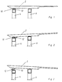
- FIG. 1 to 3 show schematic side views of a knife 2 of a knife shield driving device, which rests on a front support frame 4 and a rear support frame 6. Also shown only schematically are an immovable wedge 10 facing the underside 8 of the knife 2 and a movable wedge 12 facing the front support frame 4 of the radial control according to the invention.
- 1 shows the knife 2 in a horizontal orientation, the wedges 10, 12 being in the so-called zero position. From Fig. 1 it can be seen that the dimension of the rear support frame 6 in the radial direction by the so-called zero dimension of the wedges 10, 12, i.e. the distance between the knife 2 and the front support frame 6 resulting from the wedges 10, 12 is greater.
- Fig. 2 shows the knife 2 in a downward position, ie towards the center of the cutout. Of the movable wedge 12 is pulled back against the direction of advance in order to cause the downward inclination of the knife 2.
- Fig. 3 shows the control of the knife 2 upwards, i.e. to the mountains or the ground.
- the movable wedge 12 is moved in the direction of advance so that the knife 2 can tilt towards the mountains.
- FIG. 4 shows a side view of the radial control according to the invention in accordance with a section B-B from FIG. 7.
- the immovable wedge 10 On the underside 8 of the knife 2 there is the immovable wedge 10, the base 34 of which faces the underside 8.
- the wedge surface 14 opposite the base surface 34 of the wedge 10 lies on a wedge surface 16 of the movable wedge 12.
- the base surface 42 opposite the wedge surface 16 of the movable wedge 12 rests on an intermediate bearing 18 which is supported on the front support frame 4. Consequently, the immovable wedge 10, the movable wedge 12 and the intermediate bearing 18 are arranged between the knife 2 and the support frame 4, seen from above, towards the center of the breakout.
- the wedge surfaces 14, 16 of the wedges 10, 12 which cause the wedge effects face each other and have an identical inclination.
- the base surfaces 34, 42 of the wedges 10, 12 are thus always horizontal, i.e. aligned in the direction of breakout or perpendicular to the main plane of the support frame 4.
- a change in the inclination of the knife 2 from the horizontal or zero position results from a movement of the movable wedge 12 in the direction of advance or against the direction of advance.
- This movability of the movable wedge 12 is caused by a preferably hydraulic or pneumatic drive device, one of which is articulated to a side cheek 26 and thus to the intermediate bearing 18 Connected cylinder 36 and a piston rod 44 guided in the cylinder 36 and articulated to the movable wedge 12 are shown.
- the piston rod 44 is preferably connected to the movable wedge 12 in the end region of the movable wedge 12 opposite the breakout direction.
- the movable wedge 12 is supported on the front support frame 4 with the interposition of the intermediate bearing 18, the configuration of which is described in more detail later in FIG. 6.
- the intermediate bearing 18 is immovably arranged on the front support frame 4 in the direction of advance, so that when the movable wedge 12 moves in the direction of advance, its base 42 facing the intermediate bearing 18 is displaced on the intermediate bearing 18 in order to move the movable wedge 12 relative to the intermediate bearing 18 or to cause the front support frame 4. So that when the movable wedge 12 moves in the direction of advance, the immovable wedge 10 cannot also be moved in the direction of advance, it is secured via stops 32 of the intermediate bearing 18 in such a way that it cannot move relative to the intermediate bearing 18 or to the front support frame 4. It goes without saying that the underside 8 of the knife 2 can slide over the base 34 of the immovable wedge 10 during its propulsion without moving the immovable wedge 10 relative to the intermediate bearing 18 or to the front support frame 4 in the direction of advance.
- the movable wedge 12 In order to control the knife 2 downwards, ie towards the center of the breakout, the movable wedge 12 is moved backwards by actuating the piston rod 44 of the cylinder 36, ie counter to the direction of advance. This reduces the distance between the underside 8 of the knife 2 and the support frame 4. Because the knife 2 is immovable on the rear support frame 6 arranged in the forward direction in the direction of the mountains or the ground is stored, the reduction in distance between the underside 8 of the knife 2 and the front support frame 4 produces the desired inclination of the knife 2.
- the movable wedge 12 can be moved in the direction of advance by the piston rod 44 of the cylinder 36.
- the wedge surface 16 of the movable wedge 12 viewed in the direction of advance, is longer than the wedge surface 14 of the immovable wedge 10.
- the drive device for the movable wedge 12 consisting of the cylinder 36 and the piston rod 44 is preferably designed to be operated automatically and centrally controlled.
- the base surface 34 of the immovable wedge 10 is preferably spherical or curved or curved. The positional force or the pressure force from the knife 2 thus always acts on the immovable wedge 10 in its central region.
- the formation of the intermediate bearing 18 results in particular from FIGS. 4 and 6.
- the view of the intermediate bearing 18 according to FIG. 6 shows that the intermediate bearing 18 consists of an essentially flat base plate 20, at the free side boundaries thereof, in the circumferential direction of the support arch 4 seen side cheeks 26 are arranged, which are aligned substantially perpendicular to the base plate 20. Adjacent to the side cheeks 26 are formed middle cheeks 38, which are somewhat shorter in their cross-sectional height to the mountain or ground, than the side cheeks 26.
- the bottom plate 20 of the intermediate bearing 18 serves to support the base 42 of the movable wedge 12.
- the side cheeks 26 are in Direction of advance over the front and rear end of the front support frame 4 are also formed (FIG.
- a front part 28 of the side cheeks 26 lying in the forward direction is designed so that it can engage under a projection 30 of the support frame 4 in order to prevent the intermediate bearing 18 from being lifted off the support frame 4 (FIG. 4).
- the side cheek in the area of the rear stop 48 can have such a grip.
- the intermediate storage 18 is provided on a support 22 in the form of sections 24 on the front support frame 4 stored.
- the sections 24 have a curvature on the underside facing the front support frame 4 which corresponds to the curvature of the corresponding support frame section.
- the intermediate bearing 18 and thus the knife 2 can consequently move in the circumferential direction of the front support frame 4.
- the sections 24 also ensure a force distribution of the compressive forces or contact forces acting from the knife 2 on the support frame 4.
- Three sections 24 are preferably provided between the base plate 20 and the front support frame 4.
- two pairs of immovable wedges 10 and movable wedges 12 are provided, which are arranged between the side cheeks 26 and the respectively adjacent middle cheek 38. Seen in the circumferential direction of the front support frame 4, the cross-sectional widths of the wedges 10, 12 lying against one another are the same and correspond approximately to the distance between a side cheek 26 and each adjacent middle cheek 38.
- the underside of the knife 2 is provided with two webs 40 which extend downward towards the center of the cutout and each engage in the space between a side cheek 26 and the adjacent middle cheek 38 for guiding the knife 2.
- the side cheeks 26 and the middle cheeks 38 are consequently formed beyond the lower end of the knife 2, ie the lower end of the webs 40, to form the desired guidance of the knife 2.
- FIG. 7 also shows the articulation of the cylinder 36 on the side cheeks 26 and the articulation of the piston rod 44 of the cylinder 36 on the movable wedge 12. Also shown in FIG. 7 is the arrangement of the stops 32 for the immovable wedge 10, which are a connecting piece between the side cheeks 36 and the adjacent middle cheek 38 and are preferably welded there.
- the expedient arrangement of a further intermediate bearing between the knife 2 and the rear support frame 6 arranged at the rear in the advancing direction is not shown.
- the upper side of the base plate of the further intermediate bearing facing the knife 2 can be slightly spherical or curved or curved so that the bearing force from the knife 2 into the further intermediate storage always acts in the central area.
- FIG. 8 shows in cross section another embodiment of the radial control according to the invention in accordance with a section C - C from FIG. 9.
- This further embodiment differs in the clip-like design of an intermediate bearing 118, which is a connection between a knife 102 and a corresponding front support frame 104 forms.
- Another difference is the use of only one cylinder 136 for the back and forth movement of the two movable wedges 112 in the direction of advance of the two pairs of wedges 110, 112.
- the intermediate storage 118 has only two side cheeks 126. Middle cheeks as in the previously described embodiment are not provided.
- the side cheeks 126 are connected to one another via a base plate 120 and a cover plate 150.
- the immovable wedge 110 and the movable wedge 112 are arranged between them. The movement of the movable wedge 112 and the positional securing of the immovable wedge 110 take place as in the previously described embodiment.
- the free ends of the webs 140 of the knife 102 have a projection 152 directed outwards to the side cheeks 126.
- the free ends of the side cheeks 126 facing the knife 102 are on the one hand led upwards beyond these projections 152 and also have projections 154 which are directed inwards towards the webs 140 and overlap the projections 152.
- the clamp-like overlapping of the intermediate bearing 118 with the knife 102 is achieved via this configuration of the projections 152, 154.
- the other, free end of the side cheeks 126 facing the tunnel axis is guided in the form of a front 146 and rear stop 148 over the top shot of the support frame 104.
- the upper end of the support frame 104 is formed by a plate 158 having projections 156 at the front and rear, as seen in the axial direction of the tunnel.
- the webs 126 connecting the side walls 126 are arranged.
- the webs 160 are formed up to the support frame 104 so that they engage under the projections 156 of the plate 158, the web 160 being arranged at a distance from the projections 156.
- compression springs 162 and a connecting piece 164 are arranged in the space between the webs 160 and the protrusions 156.
- the connecting piece 164 faces the plate 158 or the projection 156 and has a surface corresponding to the curvature of the support frame 104 for bearing in this area, so that a movement of the intermediate bearing 118 in the circumferential direction of the support frame 104 is also possible in this case.
- Each connecting piece has two compression springs 162 in the region of its free ends, which are supported on the one hand on the upper side of the webs 160 and on the other hand on the lower side of the connecting piece 164.
- the clamp-like connection of the intermediate bearing 118 to the support frame 104 is accordingly carried out via the webs 160, the compression springs 162, the connecting pieces 164 and the projections 156 of the plate 158.
- the clamp-like connection of the knife 102 to the support frame 104 via the intermediate bearing 118 and the use of Compression springs 162 ensure a radial movement of the knife 102 even in the event that there should be no compressive force acting in the radial direction on the knife 102.
- the compression springs 162 provide the connection between the knife 102 and the support frame 104 on the one hand, but allow the required inclination of the knife 102 at any time when the movable wedge 112 moves for radial control of the knife 102.
- cylinders can also be used can be either controllable and / or gas or air pressure cushioned.
Landscapes
- Engineering & Computer Science (AREA)
- Mining & Mineral Resources (AREA)
- Environmental & Geological Engineering (AREA)
- Life Sciences & Earth Sciences (AREA)
- General Life Sciences & Earth Sciences (AREA)
- Geochemistry & Mineralogy (AREA)
- Geology (AREA)
- Excavating Of Shafts Or Tunnels (AREA)
- Details Of Cutting Devices (AREA)
Abstract
Claims (10)
- Ajustement radial des lames (2 ; 102) d'un bouclier de percement porte-lames, lesquelles reposent sur des chevalements (4, 6 ; 104) et sont propulsées séparément dans un ordre prédéfini, l'ajustement radial des lames (2 ; 102) nécessitant la présence de deux cales (10, 12 ; 110, 112) au moins, posées l'une sur l'autre et disposées entre les surfaces de roulement ou la face inférieure (8) desdites lames et le chevalement avant, disposé à l'avant dans le sens de propulsion, l'une des cales (10 ; 110) étant disposée sur la face inférieure (8) des lames (2 ; 102) dans une position fixe dans le sens de la propulsion relativement par rapport au chevalement (4 ; 104), et l'autre cale (12 ; 112) pouvant être déplacée, en particulier par l'intermédiaire d'un dispositif d'entraînement hydraulique ou pneumatique, vers l'avant et vers l'arrière dans le sens de la propulsion relativement par rapport au chevalement (4 ; 104), afin de pouvoir incliner les lames (2 ; 102) pour réaliser l'ajustement radial, un palier intermédiaire (18 ; 118) etant logé entre la cale mobile (12 ; 112) et le chevalement (4 ; 104).
- Ajustement radial selon la revendication 1, dans lequel le palier intermédiaire (18 ; 118) est
mobile sur le chevalement (4 ; 104) dans le sens de sa périphérie. - Ajustement radial selon la revendication 1, dans lequel les surfaces en oblique (14, 16) de la cale fixe (10 ; 110) et de la cale mobile (12 ; 112) sont placées l'une à côté de l'autre et présentent la même inclinaison, la surface oblique (16) de la cale mobile (12 ; 112) étant de préférence plus longue que la surface oblique (14) de la cale fixe (10 ; 110), en regardant dans le sens de la propulsion.
- Ajustement radial selon la revendication 1, dans lequel le palier intermédiaire (18 ; 118) est muni d'une plaque de base (20 ; 120) plane, sur laquelle est disposée la cale mobile (12 ; 112).
- Ajustement radial selon la revendication 4, dans lequel, entre la plaque de base (20 ; 120) et le chevalement (4 ; 104) est disposée une aisselle (22), dont la face inférieure orientée vers le chevalement (4 ; 104) correspond à la courbure de la zone du chevalement correspondante, l'aisselle (22) étant formée, de préférence, de plusieurs zones (24) espacées les unes des autres et disposées dans le sens périphérique du chevalement (4 ; 104).
- Ajustement radial selon la revendication 3, dans lequel le palier intermédiaire (18 ; 118) est muni d'éléments pour guider les lames (2 ; 102), les éléments étant formés de faces latérales (26 ; 126), orientées perpendiculairement par rapport à la plaque de base (20; 120), qui sont disposées sur les arêtes latérales de la plaque de base (20 ; 120).
- Ajustement radial selon la revendication 6, dans lequel les faces latérales (26 ; 126) se prolongent, dans le sens de la propulsion, au-delà de l'arête avant et de l'arête arrière du chevalement (4 ; 104) et s'étendent vers le bas, considéré par rapport au milieu du percement, au-dessus de l'arête supérieure du chevalement (4 ; 104), afin de former des butées avant et arrière pour le palier intermédiaire (18 ; 118).
- Ajustement radial selon les revendications 6 ou 7, dans lequel la partie avant (28) des faces latérales (26 ; 126), placée à l'avant dans le sens de la propulsion, s'engage sous une partie en saillie (30) du chevalement (4 ; 104), afin d'éviter le soulèvement du palier intermédiaire (18 ; 118) à partir du chevalement (4 ; 104).
- Ajustement radial selon les revendications 6 ou 7, dans lequel le palier intermédiaire (18; 118) enveloppe à la manière d'une pince le chevalement (4 ; 104) ainsi que les lames (2 ; 102), un dispositif (162) exerçant une force de pression étant monté entre le palier intermédiaire (18 ; 118) et la lame (2 ; 102) et/ou le palier intermédiaire (18 ; 118) et le chevalement (4 ; 104).
- Ajustement radial selon la revendication 1, dans lequel le dispositif d'entraînement, en particulier sous la forme d'un vérin hydraulique ou pneumatique (36 ; 136), est fixé sur le palier intermédiaire (18 ; 118), en particulier sur les faces latérales (26 ; 126), le vérin (36 ; 136) étant muni d'une tige de piston (44) extractible, disposée sur la cale mobile (12 ; 112) et articulée sur la cale mobile (12 ; 112).
Applications Claiming Priority (3)
| Application Number | Priority Date | Filing Date | Title |
|---|---|---|---|
| DE4124419A DE4124419A1 (de) | 1991-07-23 | 1991-07-23 | Radialsteuerung von messern einer messerschildvortriebsvorrichtung |
| DE4124419 | 1991-07-23 | ||
| PCT/EP1992/001677 WO1993002275A1 (fr) | 1991-07-23 | 1992-07-22 | Ajustement radial des lames d'un bouclier de percement porte-lames |
Publications (2)
| Publication Number | Publication Date |
|---|---|
| EP0595934A1 EP0595934A1 (fr) | 1994-05-11 |
| EP0595934B1 true EP0595934B1 (fr) | 1996-04-17 |
Family
ID=6436844
Family Applications (1)
| Application Number | Title | Priority Date | Filing Date |
|---|---|---|---|
| EP92915969A Expired - Lifetime EP0595934B1 (fr) | 1991-07-23 | 1992-07-22 | Ajustement radial des lames d'un bouclier de percement porte-lames |
Country Status (4)
| Country | Link |
|---|---|
| EP (1) | EP0595934B1 (fr) |
| DE (2) | DE4124419A1 (fr) |
| ES (1) | ES2089542T3 (fr) |
| WO (1) | WO1993002275A1 (fr) |
Family Cites Families (4)
| Publication number | Priority date | Publication date | Assignee | Title |
|---|---|---|---|---|
| AT354504B (de) * | 1975-05-10 | 1979-01-10 | Gewerk Eisenhuette Westfalia | Vortriebsschild fuer den tunnel- oder stollen- vortrieb u. dgl. |
| DE2742332C3 (de) * | 1977-09-20 | 1987-01-22 | Walbröhl, Heinz-Theo, Dipl.-Ing., 5300 Bonn | Lenkbare Messerschildvortriebseinrichtung und Vortriebsmesser |
| FR2441717A1 (fr) * | 1978-11-20 | 1980-06-13 | Sp K Tekhn | Bouclier utilise dans la construction de tunnels a revetement monolithe en beton presse |
| WO1990015222A1 (fr) * | 1989-06-09 | 1990-12-13 | Walbroehl H T | Dispositif d'ouverture et de soutenement de galeries d'avancement |
-
1991
- 1991-07-23 DE DE4124419A patent/DE4124419A1/de not_active Withdrawn
-
1992
- 1992-07-22 ES ES92915969T patent/ES2089542T3/es not_active Expired - Lifetime
- 1992-07-22 WO PCT/EP1992/001677 patent/WO1993002275A1/fr not_active Ceased
- 1992-07-22 EP EP92915969A patent/EP0595934B1/fr not_active Expired - Lifetime
- 1992-07-22 DE DE59206064T patent/DE59206064D1/de not_active Expired - Fee Related
Also Published As
| Publication number | Publication date |
|---|---|
| WO1993002275A1 (fr) | 1993-02-04 |
| ES2089542T3 (es) | 1996-10-01 |
| DE59206064D1 (de) | 1996-05-23 |
| DE4124419A1 (de) | 1993-01-28 |
| EP0595934A1 (fr) | 1994-05-11 |
Similar Documents
| Publication | Publication Date | Title |
|---|---|---|
| DE2319910B2 (de) | Einrichtung zur niveausteuerung eines hobels o.dgl. | |
| DE2416642A1 (de) | Transport- oder rueckvorrichtung | |
| EP0016390B1 (fr) | Mécanisme marchant | |
| DE3025235C2 (fr) | ||
| DE2540091C2 (de) | Schildausbaugestell | |
| DE2155531C3 (de) | Selbstangetriebenes Fahrzeug für ein Gesteinsbearbeitungswerkzeug und Verwendungsmöglichkeiten dafür | |
| EP0265882B1 (fr) | Dispositif de fixation d'une pelle rétro avec un engin de terrassement | |
| DE3300167C2 (fr) | ||
| DE69825958T2 (de) | Spaltmaschine | |
| DE3325795A1 (de) | Aussenliegendes schreitwerk fuer hydraulische ausbaugestelle | |
| DE1427952A1 (de) | Vorrichtung zum Wenden von Brammen und Knueppeln | |
| DE69001367T2 (de) | Vorrichtung zum abreissen von pfaehlen. | |
| DE2742332B2 (de) | Verfahren zur Steuerung der Vortriebseinrichtung eines Messerschildes sowie eine Messerschildvortriebseinrichtung und ein Vortriebsmesser zur Durchführung eines derartigen Verfahrens | |
| EP0793765A1 (fr) | Dispositif de forage et de mise en place pour boulons d'ancrage | |
| DE2934625C2 (de) | Vorrichtung zur Teilmechanisierung der Ausbauarbeiten in einem Teilschnitt-Streckenvortrieb und Verfahren zum Einbringen eines vormontierten Streckenausbaus unter Verwendung dieser Vorrichtung | |
| DE2601001C2 (fr) | ||
| WO1993002275A1 (fr) | Ajustement radial des lames d'un bouclier de percement porte-lames | |
| EP0258699B1 (fr) | Bouclier à couteaux et méthode pour l'avencement et/ou soutènement de tunnels etc. | |
| EP0846411A1 (fr) | Véhicule agricole pour distribuer de l'ensilage aux animaux | |
| DE1482916B2 (de) | Maehmaschine mit einem maehtisch | |
| DE9200236U1 (de) | Wendevorrichtung zum Drehen eines Langholzes um die Längsachse bei einer Sägemaschine | |
| DE1555670C2 (de) | Kraftfahrzeug zum Transport von kastenförmigen Baukörpern, insbesondere Fertiggaragen | |
| DE2746349C2 (fr) | ||
| DE3416385C2 (de) | Einrichtung zum Setzen von Streckenbögen | |
| DE4017259A1 (de) | Konstruktion fuer den ausbau von untertagigen hohlraeumen, besonders bergbaulichen raeumen, hauptsaechlich im bereich des strecken-strebueberganges, sowie ausbaueinrichtung zum ausbauen dieses bereiches und des hierzu sich anschliessenden streckenabschnittes |
Legal Events
| Date | Code | Title | Description |
|---|---|---|---|
| PUAI | Public reference made under article 153(3) epc to a published international application that has entered the european phase |
Free format text: ORIGINAL CODE: 0009012 |
|
| 17P | Request for examination filed |
Effective date: 19931222 |
|
| AK | Designated contracting states |
Kind code of ref document: A1 Designated state(s): CH DE ES FR GB IT LI |
|
| 17Q | First examination report despatched |
Effective date: 19950322 |
|
| GRAH | Despatch of communication of intention to grant a patent |
Free format text: ORIGINAL CODE: EPIDOS IGRA |
|
| GRAA | (expected) grant |
Free format text: ORIGINAL CODE: 0009210 |
|
| AK | Designated contracting states |
Kind code of ref document: B1 Designated state(s): CH DE ES FR GB IT LI |
|
| REG | Reference to a national code |
Ref country code: CH Ref legal event code: NV Representative=s name: A. BRAUN, BRAUN, HERITIER, ESCHMANN AG PATENTANWAE |
|
| REF | Corresponds to: |
Ref document number: 59206064 Country of ref document: DE Date of ref document: 19960523 |
|
| ET | Fr: translation filed | ||
| ITF | It: translation for a ep patent filed | ||
| PGFP | Annual fee paid to national office [announced via postgrant information from national office to epo] |
Ref country code: GB Payment date: 19960715 Year of fee payment: 5 |
|
| GBT | Gb: translation of ep patent filed (gb section 77(6)(a)/1977) |
Effective date: 19960618 |
|
| REG | Reference to a national code |
Ref country code: ES Ref legal event code: FG2A Ref document number: 2089542 Country of ref document: ES Kind code of ref document: T3 |
|
| REG | Reference to a national code |
Ref country code: ES Ref legal event code: FG2A Ref document number: 2089542 Country of ref document: ES Kind code of ref document: T3 |
|
| PLBE | No opposition filed within time limit |
Free format text: ORIGINAL CODE: 0009261 |
|
| STAA | Information on the status of an ep patent application or granted ep patent |
Free format text: STATUS: NO OPPOSITION FILED WITHIN TIME LIMIT |
|
| 26N | No opposition filed | ||
| PG25 | Lapsed in a contracting state [announced via postgrant information from national office to epo] |
Ref country code: GB Free format text: LAPSE BECAUSE OF NON-PAYMENT OF DUE FEES Effective date: 19970722 |
|
| GBPC | Gb: european patent ceased through non-payment of renewal fee |
Effective date: 19970722 |
|
| REG | Reference to a national code |
Ref country code: FR Ref legal event code: D6 |
|
| PGFP | Annual fee paid to national office [announced via postgrant information from national office to epo] |
Ref country code: FR Payment date: 20010618 Year of fee payment: 10 |
|
| PGFP | Annual fee paid to national office [announced via postgrant information from national office to epo] |
Ref country code: CH Payment date: 20010723 Year of fee payment: 10 |
|
| PGFP | Annual fee paid to national office [announced via postgrant information from national office to epo] |
Ref country code: ES Payment date: 20010730 Year of fee payment: 10 |
|
| PGFP | Annual fee paid to national office [announced via postgrant information from national office to epo] |
Ref country code: DE Payment date: 20010925 Year of fee payment: 10 |
|
| PG25 | Lapsed in a contracting state [announced via postgrant information from national office to epo] |
Ref country code: ES Free format text: LAPSE BECAUSE OF NON-PAYMENT OF DUE FEES Effective date: 20020723 |
|
| PG25 | Lapsed in a contracting state [announced via postgrant information from national office to epo] |
Ref country code: LI Free format text: LAPSE BECAUSE OF NON-PAYMENT OF DUE FEES Effective date: 20020731 Ref country code: CH Free format text: LAPSE BECAUSE OF NON-PAYMENT OF DUE FEES Effective date: 20020731 |
|
| PG25 | Lapsed in a contracting state [announced via postgrant information from national office to epo] |
Ref country code: DE Free format text: LAPSE BECAUSE OF NON-PAYMENT OF DUE FEES Effective date: 20030201 |
|
| REG | Reference to a national code |
Ref country code: CH Ref legal event code: PL |
|
| PG25 | Lapsed in a contracting state [announced via postgrant information from national office to epo] |
Ref country code: FR Free format text: LAPSE BECAUSE OF NON-PAYMENT OF DUE FEES Effective date: 20030331 |
|
| REG | Reference to a national code |
Ref country code: FR Ref legal event code: ST |
|
| REG | Reference to a national code |
Ref country code: ES Ref legal event code: FD2A Effective date: 20030811 |
|
| PG25 | Lapsed in a contracting state [announced via postgrant information from national office to epo] |
Ref country code: IT Free format text: LAPSE BECAUSE OF NON-PAYMENT OF DUE FEES;WARNING: LAPSES OF ITALIAN PATENTS WITH EFFECTIVE DATE BEFORE 2007 MAY HAVE OCCURRED AT ANY TIME BEFORE 2007. THE CORRECT EFFECTIVE DATE MAY BE DIFFERENT FROM THE ONE RECORDED. Effective date: 20050722 |