EP0595975B1 - Machine de cardage - Google Patents
Machine de cardage Download PDFInfo
- Publication number
- EP0595975B1 EP0595975B1 EP92916345A EP92916345A EP0595975B1 EP 0595975 B1 EP0595975 B1 EP 0595975B1 EP 92916345 A EP92916345 A EP 92916345A EP 92916345 A EP92916345 A EP 92916345A EP 0595975 B1 EP0595975 B1 EP 0595975B1
- Authority
- EP
- European Patent Office
- Prior art keywords
- impeller
- plenum chamber
- waste material
- machine
- chamber
- Prior art date
- Legal status (The legal status is an assumption and is not a legal conclusion. Google has not performed a legal analysis and makes no representation as to the accuracy of the status listed.)
- Expired - Lifetime
Links
Images



Classifications
-
- D—TEXTILES; PAPER
- D01—NATURAL OR MAN-MADE THREADS OR FIBRES; SPINNING
- D01G—PRELIMINARY TREATMENT OF FIBRES, e.g. FOR SPINNING
- D01G15/00—Carding machines or accessories; Card clothing; Burr-crushing or removing arrangements associated with carding or other preliminary-treatment machines
- D01G15/76—Stripping or cleaning carding surfaces; Maintaining cleanliness of carding area
- D01G15/763—Stripping or cleaning carding surfaces; Maintaining cleanliness of carding area by suction or blowing
-
- D—TEXTILES; PAPER
- D01—NATURAL OR MAN-MADE THREADS OR FIBRES; SPINNING
- D01G—PRELIMINARY TREATMENT OF FIBRES, e.g. FOR SPINNING
- D01G15/00—Carding machines or accessories; Card clothing; Burr-crushing or removing arrangements associated with carding or other preliminary-treatment machines
- D01G15/76—Stripping or cleaning carding surfaces; Maintaining cleanliness of carding area
- D01G15/80—Arrangements for stripping cylinders or rollers
- D01G15/805—Arrangements for stripping cylinders or rollers by suction or blowing
Definitions
- This invention relates to a carding machine, and is concerned with providing improved removal of dust and other waste materials which are inevitably generated during operation of the machine.
- waste material often includes waxes derived from cotton, and this is sticky, and tends to adhere to wall surfaces of the plenum chamber and any outlet passages leading to waste collection units, and this of course further aggravates the problem of build-up of waste material, rather than being discharged to the waste collection unit.
- the invention therefore seeks to provide improved means for effecting discharge of dust and other waste materials from sites at which such material is generated or collected.
- a carding machine having a feed means, a taker-in, a main carding cylinder, a doffer, a stripper arrangement, a plenum chamber located at a region of the machine where waste material is generated or collected during operation of the machine, an outlet duct leading from the plenum chamber, and means for generating negative pressure within the duct and the plenum chamber in order to discharge waste material from the plenum chamber: characterised in that an impeller is mounted for rotation at high speed within the chamber to cause turbulent air flow within the chamber to mix with the waste material; and in that a striker is arranged adjacent to the circular path of travel defined by the outermost part of the impeller during rotation so as to co-operate therewith in order to prevent build-up of waste material on the impeller.
- the carding machine has an endless conveyor belt arranged to extend below at least the taker-in, the main carding cylinder and the doffer, and means for driving the conveyor belt so that an upper run thereof travels from the stripper end towards the feed end of the carding machine, in which the plenum chamber is arranged around the conveyor at the feed end of the carding machine.
- waste is generated or collected in the plenum chamber, from where it may be extracted through the outlet duct.
- the impeller generates turbulent flow in the plenum chamber, and accordingly the waste material in the chamber is kept suspended in the air and so can efficiently be extracted therefrom.
- the fact that the waste material is kept in constant movement means that there is little or no tendency for it to collect on the surface of the plenum chamber, and accordingly the chamber can remain clean for much longer periods than has hitherto been the case. Down time of the carding machine for cleaning purposes is thus reduced.
- the impeller preferably comprises a circular cylindrical body having at least one radially extending blade mounted rigidly thereon, and preferably two or more blades are provided, distributed so that the body runs in balance.
- the blade or blades may have any suitable cross sectional shape, and should have a suitably smooth external surface.
- the impeller When the impeller is mounted in the vicinity of the conveyor belt, it is desirably located such that the cylinder generated by rotation of the radially outermost part of the element shows a clearance of not more than 1.0cm from the surface of the conveyor belt.
- the striker blade is set to cooperate with the impeller, desirably so that there is a clearance of from 1.5 to 6,5mm between the cylinder generated by the radially outermost part of the impeller during rotation thereof and the edge of the striker blade.
- a first impeller is mounted in the vicinity of the conveyor belt of the carding machine and a second impeller is mounted in the vicinity of the duct, particularly so that part thereof rotates close to the junction region between the plenum chamber and the duct.
- means is provided to monitor the operation of the impeller in the plenum chamber, so as to give advance warning of any tendency of the plenum chamber, and / or the output duct communicating therewith (the waste material discharge system), to become blocked or unduly restricted with waste material which accumulates in either or both location over a period of time.
- This monitoring means may comprise a rotation sensor to monitor the speed of rotation of the impeller, and evidently slowing down of the impeller to a speed below its normal design speed will be an indication of at least partial clogging-up of the discharge system.
- the monitoring means may comprise any suitable type of sensor arrangement which is responsive to change of speed of the impeller, for example a monitor to detect the change in speed of a drive belt or other drive arrangement coupled with the impeller.
- the monitoring means is particularly advantageously used in the management of the operation of a carding machine.
- routine cleaning to take place at regular intervals of all sites on the machine where waste is liable to accumulate, or to be collected.
- This routine maintenance work involves regular labour costs, and also down time of the machine, with current designs of carding machine, and which can be avoided by adoption of the preferred monitoring means to monitor the speed of rotation of the impeller(s) in the plenum chamber(s).
- monitoring means for the / each plenum chamber can enable advance warning to be given of a potential build-up of waste material when the impeller first slows down by a small amount from its design speed. Warning signals may then be given to personnel supervising the operation of the carding machine, or a batch of carding machines, that a particular plenum chamber (and associated discharge duct) may require maintenance work i.e. cleaning out waste material fairly soon.
- the monitoring means therefore provides in simple manner a very useful machine management facility for use with carding machines, in which material accumulation, and disposal, represents a problem.
- the invention therefore, in a further aspect provides an improved management of the operation of a carding machine using simple and more reliable monitoring of the build-up of waste material in the discharge system.
- the invention provides a carding machine having a feed means, a taker-in, a main carding cylinder, a doffer, a stripper arrangement, a plenum chamber located at a region of the machine where waste material is collected or generated during operation of the machine, an outlet duct leading from the plenum chamber, to a waste collection device, and means for generating negative pressure within the duct and the plenum chamber in order to discharge waste material: characterised in that an impeller is mounted for rotation within the plenum chamber in order to generate turbulent air flow within the chamber to mix with the waste material, and in that means is provided to monitor the operation of the impeller and to detect when the speed of the impeller falls below a design speed so as to be indicative of a build-up of waste material in the waste material discharge system, and to provide an advance warning signal that cleaning and / or maintenance of the waste material discharge system will be required in the future.
- FIG. 1 this shows a carding machine designated generally by reference 100 and comprising a feed plate 1, a feed roller 2, a takerin 3, a main carding cylinder 4, a set of flats 5, a doffer 6, a stripper roll 7, and a condenser and calender roll arrangement 8.
- a carding machine designated generally by reference 100 and comprising a feed plate 1, a feed roller 2, a takerin 3, a main carding cylinder 4, a set of flats 5, a doffer 6, a stripper roll 7, and a condenser and calender roll arrangement 8.
- the detailed construction of the carding machine may, of course, be capable of considerable variation, as is well known in the art.
- An endless conveyor belt 9 is arranged to extend below the takerin, main carding cylinder, doffer and stripper roll, and it is driven so that an upper run 10 thereof travels from the stripper end towards the feed end of the carding machine.
- a plenum chamber 11 is arranged at the feed end of the carding machine to enclose the end of the conveyor belt, and a duct 12 leads from the plenum chamber.
- the duct is connected to an extraction system so that waste material is sucked from the plenum chamber through the duct.
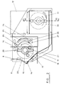
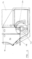
- Figures 2 and 3 show the plenum chamber 11 in more detail.
- Mounted within the chamber are plates 13 which extend the full width of the chamber, an edge 14 of one of the plates lying closely adjacent to the surface of the conveyor 9.
- the plates are disposed so that waste falling from the conveyor is guided to the lower part of the plenum chamber.
- a rotatable element or impeller 14 is mounted for rotation within the plenum chamber.
- the element comprises a circular cylindrical body 15 mounted on a shaft 16 that extends through the chamber and is supported by bearings 17, 18 externally of the chamber.
- the shaft 16 carries a drive wheel 19 and may be driven from any part of the drive system of the carding machine.
- the shaft also carries a rotation sensor 19a.
- the body 15 has two rigid blades 20, 21 extending radially therefrom.
- the body and blades may be formed as an integral casting from a suitable plastics material, or as a smooth surfaced aluminium extrusion.
- the body is mounted in a position such that the cylindrical surface 22 generated by the blade tips during rotation thereof is spaced from the surface of the conveyor belt by a distance x which is desirably no more than 1.0cm.
- a striker blade 23 extends between two mounts such as 24, one at each side of the plenum chamber.
- Each mount is pivotally mounted to the chamber wall about a pivot 25 and can be locked in a range of required positions by a locking bolt cooperating with an elongate adjustment slot 26.
- the striker blade can thus be set so that its tip 27 lies at a required distance from the surface 22 generated by the blade tip during rotation thereof, that clearance desirably being from 1.5 to 6.5mm. If there should be any tendency of waste fibres to become wrapped around the element 30, or its drive shaft, in the form of a formed ring of fibres and waste, this will be stripped off by the leading end of the striker plate 31.
- waste material removed from the rotating members of the carding machine will fall to the conveyor belt 10 and will be conveyed thereby into the plenum chamber 11.
- the material falls from the belt in the plenum chamber and is sucked from that chamber by vacuum applied to the duct 12.
- Rotating the impeller 14 at high speed within the plenum chamber will generate turbulent air flow in the plenum chamber and maintain the waste material suspended in the air within that chamber so that it can efficiently be extracted therefrom. If any blockage does occur then the resultant deceleration of impeller 14 will be sensed by the detector and the carding machine may be stopped for the blockage to be cleared.
- FIG. 2 shows a possible location for an additional rotatable element 30 having the same form as element 14 and having an associated striker blade 31.
- the element 30 is located immediately beneath the duct 12 to assist movement of the waste from the plenum chamber into the duct, and prevent blocking in the shoulder region 32 ( Figure 3) where the duct meets the plenum chamber.
- the rotatable element 30 may be raised from the position shown in Figure 2 so that it lies closer to the shoulder 32 and indeed the element 30 may have one axial section of greater diameter than the other, the section of greater diameter actually projecting into the entrance to the duct.
- Element 30 may be the same as or different from, element 14, and may be rotated at a speed that is the same as, or different from, that of the element 14.
- Figure 4 shows an alternative arrangement wherein parts similar to those in Figure 2 are given the same reference numerals with the suffix "a".
- the rotatable element 14a is mounted in the plenum chamber towards the bottom thereof and in an intermediate position between the conveyor 9a and the duct 12a, so that the single element may create sufficient turbulence throughout the chamber.
- Figure 1 shows a plenum chamber at the feed end of the carding machine, namely at the delivery end of conveyor belt 9, but there are other sites at which dust / waste material may be generated, or be collected, and which would benefit from provision of a plenum chamber and associated rotatable element mounted therein.
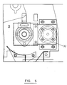
- Figures 5 and 6 show a drive train for driving a rotatable element which is housed within a plenum chamber located within the endless path followed by the travelling flats 5.
- the drive to the rotatable element is taken from the drive to a drive pulley / sprocket which drives the flats 5 along their path of travel.
- Figure 5 is an end view of a drive arrangement for driving both the flats 5 and the rotatable element, and includes a drive motor 32.
- rotatable element 33 is mounted on shaft 34 for rotation therewith, shaft 34 being arranged to be driven by motor 32.
- a drive train (not shown) moves the flats 5 (see Figure 1) along their endless path, and a so-called nug wheel 35 mounted freely on shaft 34 forms an idler mechanism to guide the movement of the flats.
- the plenum chamber (not shown) and the associated rotatable element are housed within either one of the return ends 36 or 37 (see Figure 1) of the endless path of the flats 5.
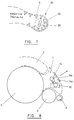
- FIG. 7 is a schematic illustration of a plenum chamber 38 and associated rotatable element 39 associated with return end 36 of the endless path of travel of the flats 5.
- a discharge duct will communicate with the plenum chamber 38, to discharge dust / waste material generated and collected at this region within the envelope of the path of travel of the flats 5.
- FIG 8 shows schematically the provision of plenum chamber 11 over taker-in 3 and adjacent to one of the return ends of the endless path of the moving flats 5.
- Plenum chamber 11 has a door 11a on which impeller 14 is mounted via a support 14a, and opening of the door allows the impeller to swing out of the chamber 11 to facilitate cleaning or maintenance when required.
- the provision of some form of monitoring means to monitor the operation of the rotatable element in the or each plenum chamber is particularly advantageous, both in management of the operation of a carding engine, or a batch of carding engines.
- a rotation sensor 19a monitors the speed of rotation of a drive shaft 16 on which rotatable element or impeller 14 is mounted.
- any slowing down of the element to a speed below its design speed will be an indication of at least partial clogging-up of the discharge system, (the plenum chamber, the discharge duct or the outlet to a waste collection unit), and this may enable warning signals to be triggered well in advance of any dangerous or hazardous situation developing. This will enable remedial action to be taken in good time, and therefore this monitoring of the speed of the rotatable element will provide early warning of this potentially hazardous condition.
- monitoring means for monitoring the operation of the rotatable element in the plenum chamber enables significantly improved management of the operation of a carding engine, or batch of carding engines.
- the engine(s) can be operated and cleaning carried out only when necessary, of which early warning will be given of need for future cleaning e.g. in ten minutes time or so, by monitoring slow down in the speed of rotation of the rotatable element from its design speed.
Landscapes
- Engineering & Computer Science (AREA)
- Textile Engineering (AREA)
- Preliminary Treatment Of Fibers (AREA)
Abstract
Claims (11)
- Machine de cardage (100) comprenant un moyen d'alimentation (2), un dispositif preneur (3), un cylindre principal de cardage (4), un dispositif de sortie (6), un dispositif séparateur (7), une chambre de distribution (11) placée en une région de la machine dans laquelle les déchets sont formés ou collectés pendant le fonctionnement de la machine, une conduite de sortie (12) partant de la chambre de distribution (11), et un moyen pour créer une dépression à l'intérieur de la conduite (12) et de la chambre de distribution (11) afin de dégager les déchets de la chambre de distribution (11) :
caractérisée en ce qu'une hélice (14) est montée rotative à grande vitesse à l'intérieur de la chambre pour créer un flux d'air turbulent à l'intérieur de la chambre et le mélanger avec les déchets ;
et en ce qu'un déflecteur (23) est disposé adjacent au trajet circulaire de déplacement défini par la partie la plus extérieure de l'hélice pendant sa rotation afin de coopérer avec l'hélice pour empêcher l'accumulation de déchets sur l'hélice. - Machine selon la revendication 1, dans laquelle est montée une bande transporteuse sans fin (9) qui s'étend au moins sous le dispositif preneur (3), le cylindre principal de cardage (4) et le dispositif de sortie (6), et dans laquelle le plateau supérieur (10) de la bande transporteuse (9) est agencé pour se déplacer depuis l'extrémité du séparateur en direction de l'extrémité d'alimentation de la machine de cardage, et dans laquelle la chambre de distribution (11) est disposée autour de la bande transporteuse (9) à l'extrémité d'alimentation de la machine de cardage.
- Machine selon la revendication 1 ou 2, dans laquelle l'hélice (14) comprend une âme cylindrique circulaire (15) sur laquelle est rigidement fixée au moins une pale orientée radialement (20, 21).
- Machine selon la revendication 3, dans laquelle l'âme cylindrique (15) porte au moins deux pales (20, 21) montées sur l'âme de manière que cette dernière soit équilibrée en rotation et possède une surface extérieure lisse.
- Machine selon la revendication 2, dans laquelle l'écart entre la partie radialement la plus extérieure de l'hélice (14) et la surface de la bande transporteuse (9) n'est pas supérieur à 1 cm.
- Machine selon l'une quelconque des revendications 1 à 5, dans laquelle une première hélice est montée dans la chambre de distribution (11), et une seconde hélice est montée au voisinage de l'entrée de la conduite (12).
- Machine selon l'une quelconque des revendications 1 à 6, comprenant un moyen de surveillance (19a) pour surveiller le mouvement de l'hélice (14) dans la chambre de distribution (11).
- Machine selon la revendication 7, comprenant un dispositif avertisseur couplé au moyen de surveillance (19a) et ayant pour fonction d'avertir en cas de réduction de la vitesse de l'hélice (14).
- Machine selon l'une quelconque des revendications 1 à 8, dans laquelle la chambre de distribution (11), ou une chambre de distribution respective est disposée dans la région d'un ou plusieurs des éléments suivants : le dispositif preneur (3) ; le dispositif séparateur (7) ; à l'intérieur de l'enveloppe de la trajectoire de déplacement des cylindres lisses (5) ; ou à l'intérieur de l'une des extrémités de retour (36, 37) autour desquelles les méplats (5) sont mobiles.
- Machine selon la revendication 9, dans laquelle la chambre de distribution est placée dans l'une des extrémités de retour (36, 37) et dans laquelle l'hélice (14) contenue dans cette chambre est disposée pour être entraînée par le même moyen d'entraînement que celui qui communique le mouvement d'entraînement aux cylindres lisses (5) le long du trajet fermé.
- Machine de cardage (100) ayant un moyen d'alimentation (2), un dispositif preneur (3), un cylindre principal de cardage (4) un dispositif de sortie (6), un dispositif séparateur (7), une chambre de distribution (11) placée dans une zone de la machine dans laquelle les déchets sont collectés ou formés pendant le fonctionnement de la machine, une conduite de sortie (12) partant de la chambre de distribution (11) vers un dispositif de collecte des déchets, et un moyen pour créer une dépression à l'intérieur de la conduite (12) et de la chambre de distribution (11) afin de dégager les déchets :
caractérisée en ce qu'une hélice (14) est montée en rotation à grande vitesse à l'intérieur de la chambre de distribution (11) pour créer un courant d'air turbulent à l'intérieur de la chambre et le mélanger avec les déchets, et en ce qu'un moyen (19a) est prévu pour surveiller le fonctionnement de l'hélice (14) et pour détecter à quel moment la vitesse de l'hélice (14) descend en-dessous d'une vitesse nominale de façon à pouvoir signaler une accumulation de déchets dans le système de dégagement des déchets (14, 12), et à former d'avance un signal avertissant que le nettoyage et/ou la maintenance du système de dégagement des déchets seront nécessaires dans l'avenir.
Applications Claiming Priority (3)
| Application Number | Priority Date | Filing Date | Title |
|---|---|---|---|
| GB9116083 | 1991-07-25 | ||
| GB919116083A GB9116083D0 (en) | 1991-07-25 | 1991-07-25 | Carding machine |
| PCT/GB1992/001365 WO1993002236A1 (fr) | 1991-07-25 | 1992-07-23 | Machine de cardage |
Publications (2)
| Publication Number | Publication Date |
|---|---|
| EP0595975A1 EP0595975A1 (fr) | 1994-05-11 |
| EP0595975B1 true EP0595975B1 (fr) | 1995-11-29 |
Family
ID=10698970
Family Applications (1)
| Application Number | Title | Priority Date | Filing Date |
|---|---|---|---|
| EP92916345A Expired - Lifetime EP0595975B1 (fr) | 1991-07-25 | 1992-07-23 | Machine de cardage |
Country Status (5)
| Country | Link |
|---|---|
| EP (1) | EP0595975B1 (fr) |
| CN (1) | CN1074251A (fr) |
| DE (1) | DE69206420T2 (fr) |
| GB (1) | GB9116083D0 (fr) |
| WO (1) | WO1993002236A1 (fr) |
Families Citing this family (7)
| Publication number | Priority date | Publication date | Assignee | Title |
|---|---|---|---|---|
| CN100510211C (zh) * | 2005-12-26 | 2009-07-08 | 上海杰事杰新材料股份有限公司 | 一种梳理机的喂入和梳理系统 |
| DE102007037426A1 (de) * | 2006-10-20 | 2008-04-24 | TRüTZSCHLER GMBH & CO. KG | Vorrichtung zur Fasersortierung bzw. -selektion eines Faserverbandes aus Textilfasern, insbesondere zum Kämmen |
| DE102008004098A1 (de) * | 2007-06-29 | 2009-01-02 | TRüTZSCHLER GMBH & CO. KG | Vorrichtung zur Fasersortierung bzw. -selektion eines Faserverbandes aus Textilfasern, insbesondere zum Kämmen, der über Zuführmittel einer Fasersortiereinrichtung, insbesondere Kämmeinrichtung zugeführt wird |
| US7823257B2 (en) * | 2007-06-29 | 2010-11-02 | Fa. Trützschler GmbH & Co. KG | Apparatus for the fibre-sorting or fibre-selection of a fibre bundle comprising textile fibres, especially for combing |
| CN103160958A (zh) * | 2011-12-15 | 2013-06-19 | 天津天纺投资控股有限公司北洋纺织分公司 | 梳棉机风压检测防火装置 |
| CN108505151A (zh) * | 2018-05-28 | 2018-09-07 | 依韵家纺(浙江)有限公司 | 一种带有混棉装置的无胶棉用喂棉机 |
| CN115094548B (zh) * | 2022-06-17 | 2024-08-23 | 安徽富春纺织有限公司 | 梳棉机龙头飞花自动清理装置及方法 |
Family Cites Families (6)
| Publication number | Priority date | Publication date | Assignee | Title |
|---|---|---|---|---|
| GB346186A (en) * | 1929-05-23 | 1931-04-09 | Charles Gegauff | Improvements relating to flat carding engines |
| GB791082A (en) * | 1955-01-17 | 1958-02-26 | William Ewart & Son Ltd | Improvements in or relating to apparatus for use in collecting or disposing of dust, fibrous waste or the like waste material generated by a machine |
| CH395812A (de) * | 1962-02-02 | 1965-07-15 | Rieter Ag Maschf | Verfahren und Vorrichtung zur Verminderung der Füllung der Tambourgarnitur einer Karde |
| US3376610A (en) * | 1963-08-06 | 1968-04-09 | Coats & Clark | Waste removal for carding machines |
| DE2145053A1 (de) * | 1971-09-09 | 1973-03-22 | Krupp Gmbh | Vorrichtung zum lueften von krempelwalzen |
| AU5443690A (en) * | 1989-04-18 | 1990-11-16 | Lappage, James | A method and apparatus for cleaning fibrous materials |
-
1991
- 1991-07-25 GB GB919116083A patent/GB9116083D0/en active Pending
-
1992
- 1992-07-23 DE DE69206420T patent/DE69206420T2/de not_active Expired - Fee Related
- 1992-07-23 EP EP92916345A patent/EP0595975B1/fr not_active Expired - Lifetime
- 1992-07-23 WO PCT/GB1992/001365 patent/WO1993002236A1/fr not_active Ceased
- 1992-07-25 CN CN 92110110 patent/CN1074251A/zh active Pending
Also Published As
| Publication number | Publication date |
|---|---|
| GB9116083D0 (en) | 1991-09-11 |
| EP0595975A1 (fr) | 1994-05-11 |
| DE69206420D1 (de) | 1996-01-11 |
| WO1993002236A1 (fr) | 1993-02-04 |
| CN1074251A (zh) | 1993-07-14 |
| DE69206420T2 (de) | 1996-05-15 |
Similar Documents
| Publication | Publication Date | Title |
|---|---|---|
| US3486309A (en) | Fiber waste disposal system for textile machines | |
| US4753665A (en) | Method and apparatus for controlling the suction pressure in a dust collecting duct | |
| EP0595975B1 (fr) | Machine de cardage | |
| JP4709193B2 (ja) | 紡績準備工程で綿花の如き繊維材料を分離して加工機械に供給する装置 | |
| CN102011218A (zh) | 纤维的喂入装置及方法 | |
| US4458381A (en) | Cotton ginning system embodying a lint cleaner | |
| CN1035632C (zh) | 纤维材料特别是棉花的开清设备 | |
| JPH0348222Y2 (fr) | ||
| EP1004693A2 (fr) | Appareil de préparation et d'ouverture de flocs de fibres pour le chargement d'une carde | |
| US6298522B1 (en) | Apparatus for removing foreign material from a fiber processing line | |
| US4227285A (en) | Textile card cleaning apparatus | |
| US3284140A (en) | Separating-distributing device for textile fibers | |
| GB2372260A (en) | Device on a carding machine for collecting data relating to light fibre waste | |
| CN100507103C (zh) | 分离杂质的装置 | |
| US5454219A (en) | Means for providing air flow in a trash removal chamber of an open-end spinning unit | |
| US6185787B1 (en) | Fiber flock cleaner | |
| US5926919A (en) | Card waste monitoring | |
| US4811464A (en) | Pneumatic assembly for waste removal | |
| EP0338802B1 (fr) | Machine de cardage | |
| US3327457A (en) | Apparatus for the aspiration of lint and thread waste in textile machines | |
| US4244720A (en) | Fiber waste and cullet collection process and apparatus therefor | |
| US3604061A (en) | Apparatus for delivery end cleaning of carding machines | |
| US2157684A (en) | Apparatus for cleaning and opening cotton or like fibrous material | |
| US5481862A (en) | Pneumatically operated debris removal device for an open-end spinning device | |
| US4087888A (en) | Method and apparatus for removing waste settling under carding machine or the like |
Legal Events
| Date | Code | Title | Description |
|---|---|---|---|
| PUAI | Public reference made under article 153(3) epc to a published international application that has entered the european phase |
Free format text: ORIGINAL CODE: 0009012 |
|
| 17P | Request for examination filed |
Effective date: 19940130 |
|
| AK | Designated contracting states |
Kind code of ref document: A1 Designated state(s): CH DE LI |
|
| 17Q | First examination report despatched |
Effective date: 19950112 |
|
| GRAA | (expected) grant |
Free format text: ORIGINAL CODE: 0009210 |
|
| AK | Designated contracting states |
Kind code of ref document: B1 Designated state(s): CH DE LI |
|
| REF | Corresponds to: |
Ref document number: 69206420 Country of ref document: DE Date of ref document: 19960111 |
|
| REG | Reference to a national code |
Ref country code: CH Ref legal event code: NV Representative=s name: A. KERR AG PATENTANWAELTE |
|
| PLBE | No opposition filed within time limit |
Free format text: ORIGINAL CODE: 0009261 |
|
| 26N | No opposition filed | ||
| PGFP | Annual fee paid to national office [announced via postgrant information from national office to epo] |
Ref country code: CH Payment date: 19990621 Year of fee payment: 8 |
|
| PGFP | Annual fee paid to national office [announced via postgrant information from national office to epo] |
Ref country code: DE Payment date: 19990628 Year of fee payment: 8 |
|
| PG25 | Lapsed in a contracting state [announced via postgrant information from national office to epo] |
Ref country code: LI Free format text: LAPSE BECAUSE OF NON-PAYMENT OF DUE FEES Effective date: 20000731 Ref country code: CH Free format text: LAPSE BECAUSE OF NON-PAYMENT OF DUE FEES Effective date: 20000731 |
|
| REG | Reference to a national code |
Ref country code: CH Ref legal event code: PL |
|
| PG25 | Lapsed in a contracting state [announced via postgrant information from national office to epo] |
Ref country code: DE Free format text: LAPSE BECAUSE OF NON-PAYMENT OF DUE FEES Effective date: 20010501 |