EP0596177A1 - Ancrage pour un ligament synthétique, en particulier pour un ligament croisé du genou et procédé d'implantation d'un ligament synthétique au moyen d'un tel ancrage - Google Patents
Ancrage pour un ligament synthétique, en particulier pour un ligament croisé du genou et procédé d'implantation d'un ligament synthétique au moyen d'un tel ancrage Download PDFInfo
- Publication number
- EP0596177A1 EP0596177A1 EP92810839A EP92810839A EP0596177A1 EP 0596177 A1 EP0596177 A1 EP 0596177A1 EP 92810839 A EP92810839 A EP 92810839A EP 92810839 A EP92810839 A EP 92810839A EP 0596177 A1 EP0596177 A1 EP 0596177A1
- Authority
- EP
- European Patent Office
- Prior art keywords
- pin
- bone
- passage opening
- guide channel
- section
- Prior art date
- Legal status (The legal status is an assumption and is not a legal conclusion. Google has not performed a legal analysis and makes no representation as to the accuracy of the status listed.)
- Granted
Links
Images
Classifications
-
- A—HUMAN NECESSITIES
- A61—MEDICAL OR VETERINARY SCIENCE; HYGIENE
- A61F—FILTERS IMPLANTABLE INTO BLOOD VESSELS; PROSTHESES; DEVICES PROVIDING PATENCY TO, OR PREVENTING COLLAPSING OF, TUBULAR STRUCTURES OF THE BODY, e.g. STENTS; ORTHOPAEDIC, NURSING OR CONTRACEPTIVE DEVICES; FOMENTATION; TREATMENT OR PROTECTION OF EYES OR EARS; BANDAGES, DRESSINGS OR ABSORBENT PADS; FIRST-AID KITS
- A61F2/00—Filters implantable into blood vessels; Prostheses, i.e. artificial substitutes or replacements for parts of the body; Appliances for connecting them with the body; Devices providing patency to, or preventing collapsing of, tubular structures of the body, e.g. stents
- A61F2/02—Prostheses implantable into the body
- A61F2/08—Muscles; Tendons; Ligaments
- A61F2/0811—Fixation devices for tendons or ligaments
- A61F2002/0817—Structure of the anchor
- A61F2002/0823—Modular anchors comprising a plurality of separate parts
- A61F2002/0835—Modular anchors comprising a plurality of separate parts with deformation of anchor parts, e.g. expansion of dowel by set screw
-
- A—HUMAN NECESSITIES
- A61—MEDICAL OR VETERINARY SCIENCE; HYGIENE
- A61F—FILTERS IMPLANTABLE INTO BLOOD VESSELS; PROSTHESES; DEVICES PROVIDING PATENCY TO, OR PREVENTING COLLAPSING OF, TUBULAR STRUCTURES OF THE BODY, e.g. STENTS; ORTHOPAEDIC, NURSING OR CONTRACEPTIVE DEVICES; FOMENTATION; TREATMENT OR PROTECTION OF EYES OR EARS; BANDAGES, DRESSINGS OR ABSORBENT PADS; FIRST-AID KITS
- A61F2/00—Filters implantable into blood vessels; Prostheses, i.e. artificial substitutes or replacements for parts of the body; Appliances for connecting them with the body; Devices providing patency to, or preventing collapsing of, tubular structures of the body, e.g. stents
- A61F2/02—Prostheses implantable into the body
- A61F2/08—Muscles; Tendons; Ligaments
- A61F2/0811—Fixation devices for tendons or ligaments
- A61F2002/0847—Mode of fixation of anchor to tendon or ligament
- A61F2002/0864—Fixation of tendon or ligament between anchor elements, e.g. by additional screws in the anchor, anchor crimped around tendon
-
- A—HUMAN NECESSITIES
- A61—MEDICAL OR VETERINARY SCIENCE; HYGIENE
- A61F—FILTERS IMPLANTABLE INTO BLOOD VESSELS; PROSTHESES; DEVICES PROVIDING PATENCY TO, OR PREVENTING COLLAPSING OF, TUBULAR STRUCTURES OF THE BODY, e.g. STENTS; ORTHOPAEDIC, NURSING OR CONTRACEPTIVE DEVICES; FOMENTATION; TREATMENT OR PROTECTION OF EYES OR EARS; BANDAGES, DRESSINGS OR ABSORBENT PADS; FIRST-AID KITS
- A61F2/00—Filters implantable into blood vessels; Prostheses, i.e. artificial substitutes or replacements for parts of the body; Appliances for connecting them with the body; Devices providing patency to, or preventing collapsing of, tubular structures of the body, e.g. stents
- A61F2/02—Prostheses implantable into the body
- A61F2/08—Muscles; Tendons; Ligaments
- A61F2/0811—Fixation devices for tendons or ligaments
- A61F2002/0876—Position of anchor in respect to the bone
- A61F2002/0882—Anchor in or on top of a bone tunnel, i.e. a hole running through the entire bone
Definitions
- the invention relates to an anchoring for an artificial ligament, in particular a cruciate ligament of a knee joint, which is guided through a guide channel formed in a bone, the anchoring containing a holding element supported in the bone and receiving an end section of the ligament and a clamping element which can be clamped against this end section.
- the invention further relates to a method for implanting an artificial ligament into a bone by means of such anchoring.
- An anchoring of the type mentioned which is known from EP-A-0 465 408, contains a conical anchoring sleeve which can be inserted into the guide channel as the holding element and a radially deformable clamping sleeve which can be inserted into the guide channel to hold the band in place.
- a similar anchoring of the type mentioned is known from EP-A-0 232 049, which shows conical clamping elements, each of which is inserted into a stocking-like band extension and clamped over this against an anchoring sleeve which can be inserted into the guide channel and which in turn can be retensioned.
- the known anchors require additional devices and / or relatively complex adjustment work for tensioning or possibly retensioning the implanted band in order to coordinate the opposing movements of band stretching and clamping in such a way that the band is fixed with the desired pretension.
- the object of the invention is to provide an anchoring which is improved in particular in this respect and which ensures precise setting and / or readjustment of a predetermined pretension of the implanted band using simple means and with little effort and time.
- the anchoring designed according to the invention permits a functional separation of the work steps required for setting the pretension of the band and the steps required for setting the clamping force, in that the clamping force can be set from the outside independently of the respective pretensioning of the band.
- the arrangement according to the invention also results in simple preprocessing in the bone, in that the guide channel intended for receiving the band and the overlapping bore intended for receiving the pin each match and adapt exclusively to the dimensions of the part in question - the band or the pin can be carried out without further post-processing.
- the band can easily be drawn through the guide channel and the passage opening of the pin into the bone and on the outside of the bone, e.g.
- the band can be drawn in from an endless stack of the appropriate length and, after clamping, cut off flush with the outer surface of the bone.
- the parts of the anchoring can also be carried out essentially flush with the bone surface.
- the method according to the invention enables anchoring of the anchoring which is gentle on the bone tissue and a secure pretensioning and fastening of the implanted band in simple, separate work steps.
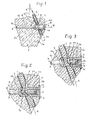
- an artificial ligament 1 in the example shown an artificial cruciate ligament of a knee joint, is passed through a guide channel 3 formed in a bone 2, as shown in the tibia (tibia), and held in an anchorage 4.
- the other end of the band 1 is held in a counterpart to the bone 1, not shown, in the present example in the thigh bone (femur), which can be provided with a corresponding anchoring 4.
- the guide channel 3 is formed by a bore which passes through the bone 2 at an acute angle V to its longitudinal axis L.
- the anchor 4 contains a holding element in the form of a pin 5 which can be inserted transversely to the direction of pull (arrow Z) of the band 1 and a clamping element in the form of an adjusting screw 6 which is arranged in an axial bore 7 of the pin 5 and which can be designed with a pointed end 6a and with an internal hexagon 6b .
- the pin 5 is arranged in a stepped bore 8 which crosses the bone 2 and which intersects the guide channel 3 and which forms an angle W with the section of the guide channel 3 which runs in the pulling direction (arrow Z) of the band 1 against the interior of the bone 2, which is less than 90 ° .
- Bone 2 is tense.
- the bore 8 runs approximately parallel to the “tibial plateau” determined by condyles 10 and 11 of the bone 2, the angle W being approximately 60 to 70. It goes without saying that any angle W can be selected which ensures a component of the tensile force which is considered sufficient.
- the set screw 6 is arranged in an end section 5a of the pin 5 which merges into a remaining length section 5c of smaller diameter via a conical section 5b.
- the end section 5a is provided with a passage opening 12 passing through it in the transverse direction and suitable for passing the tape 1, which in the example shown is formed by a bore which can be positioned in alignment with the guide channel 3, the diameter of which corresponds to that of the guide channel 3 and the axis A of which Longitudinal axis B of the pin 5 includes an angle which corresponds to the angle W between the guide channel 3 and the bore 8 of the bone 2.
- a corresponding slot running through in the transverse direction can also be provided as the passage opening 12.
- the internally threaded axial bore 7 of the pin 5 opens into the passage opening 12, in which the set screw 6 - in the example shown with a hexagon wrench - is adjustable and can be clamped against the section of the band 1 passing through the passage opening 12. 1 and 2, the axial bore 7 can be designed with a depth that extends beyond the corresponding dimension of the passage opening 12, so that the band 1 when the set screw 6 is tightened into the end section 7a of the bore 7 pushed in and an additional securing of the strap fastening is achieved.
- the axial bore 7 of the pin 5 can also end in the passage opening 12, so that the band 1 is pressed against the wall of the passage opening 12 by the adjusting screw 6 - or a corresponding other clamping element - and without additional deformation can be kept more gently.
- the pin 5 can preferably be designed as a continuous component over the relevant cross-sectional dimension of the bone 2, which extends over the two opposite edge parts 2a and 2b of the cortex of the bone 2 and with its two ends in these relatively hard edge parts 2a and 2b of the bone tissue is supported. Accordingly, stress on the relatively soft inner part, the cancellous bone, of the bone tissue by the pin 5 is avoided and a permanent, precise positioning of the pin 5 is ensured.
- the collar portion 13 can be formed by a flange-like extension provided on the end section 5a, by means of which the pin 5 is supported on the outside of the bone 2.
- the collar portion 13 can be essentially flush with the outside of the bone 2 or, as shown, by a small amount, e.g. 1 mm, protrude.
- the collar section 13 can furthermore be provided with bores 14 for receiving driver pins of a setting instrument, not shown, through which the pin 5 can be inserted, adjusted and removed.
- a first hole corresponding to a predetermined position of the guide channel 3 is made in the bone tissue, for example in a first step.
- This is followed in a second step, e.g. B. by means of a drilling jig, not shown, of a known type, at a predetermined angle W overlapping the first bore, intended for receiving the longitudinal section 5c of the pin 5, through-going second bore 8 is made in the bone, which in the overlap region corresponds to the dimensions of the end section 5a to be recorded the pin 5 is expanded.
- the pin 5 provided with the passage opening 12 is inserted into the bore 8 and positioned with the passage opening 12 aligned with the guide channel 3, the shoulder section 5b being able to be placed against a corresponding shoulder section of the bore 8.
- the artificial band 1 is passed through the passage formed by the guide channel 3 and the passage opening 12, the dash-dotted line in FIG. 1 Lower band end 1 a shown outside the guide channel 3 is detected and, if necessary, can be brought to a predetermined pretension, for example by means of a spring balance, if the other band end is already anchored to the counterpart of the joint, not shown.
- the set screw 6 is finally inserted into the bore 7 of the pin 5 and clamped over the section of the tape 1 passing through the passage opening 12 against a support portion of the pin 5 facing the tape 1, whereupon the tape end 1 protruding from the guide channel 3
- the outer surface of the bone 2 is cut off flush.
- the bore 8 intended for receiving the pin 5 can also be designed as the first bore and the guide channel 3 as the second bore.
- any other screw type or a corresponding one, e.g. resilient clamping element can be used.
- the anchorage according to the invention is also suitable for other applications, e.g. in the area of the spine or shoulder joint.
Landscapes
- Health & Medical Sciences (AREA)
- Orthopedic Medicine & Surgery (AREA)
- Rehabilitation Therapy (AREA)
- Rheumatology (AREA)
- Cardiology (AREA)
- Oral & Maxillofacial Surgery (AREA)
- Transplantation (AREA)
- Engineering & Computer Science (AREA)
- Biomedical Technology (AREA)
- Heart & Thoracic Surgery (AREA)
- Vascular Medicine (AREA)
- Life Sciences & Earth Sciences (AREA)
- Animal Behavior & Ethology (AREA)
- General Health & Medical Sciences (AREA)
- Public Health (AREA)
- Veterinary Medicine (AREA)
- Prostheses (AREA)
- Surgical Instruments (AREA)
Priority Applications (4)
| Application Number | Priority Date | Filing Date | Title |
|---|---|---|---|
| AT92810839T ATE161703T1 (de) | 1992-11-02 | 1992-11-02 | Verankerung für ein künstliches band, insbesondere ein kreuzband eines kniegelenks |
| DE59209122T DE59209122D1 (de) | 1992-11-02 | 1992-11-02 | Verankerung für ein künstliches Band, insbesondere ein Kreuzband eines Kniegelenks |
| EP92810839A EP0596177B1 (fr) | 1992-11-02 | 1992-11-02 | Ancrage pour un ligament synthétique, en particulier pour un ligament croisé du genou |
| US08/146,339 US5376119A (en) | 1992-11-02 | 1993-11-01 | Attachment for an artificial ligament, and a process for implantation |
Applications Claiming Priority (1)
| Application Number | Priority Date | Filing Date | Title |
|---|---|---|---|
| EP92810839A EP0596177B1 (fr) | 1992-11-02 | 1992-11-02 | Ancrage pour un ligament synthétique, en particulier pour un ligament croisé du genou |
Publications (2)
| Publication Number | Publication Date |
|---|---|
| EP0596177A1 true EP0596177A1 (fr) | 1994-05-11 |
| EP0596177B1 EP0596177B1 (fr) | 1998-01-07 |
Family
ID=8212016
Family Applications (1)
| Application Number | Title | Priority Date | Filing Date |
|---|---|---|---|
| EP92810839A Expired - Lifetime EP0596177B1 (fr) | 1992-11-02 | 1992-11-02 | Ancrage pour un ligament synthétique, en particulier pour un ligament croisé du genou |
Country Status (4)
| Country | Link |
|---|---|
| US (1) | US5376119A (fr) |
| EP (1) | EP0596177B1 (fr) |
| AT (1) | ATE161703T1 (fr) |
| DE (1) | DE59209122D1 (fr) |
Cited By (8)
| Publication number | Priority date | Publication date | Assignee | Title |
|---|---|---|---|---|
| FR2747913A1 (fr) * | 1996-04-25 | 1997-10-31 | Decuypere Dominique | Dispositif de blocage en translation d'un ligament et ligaments pourvus d'un tel dispositif de blocage |
| US5899938A (en) * | 1996-11-27 | 1999-05-04 | Joseph H. Sklar | Graft ligament anchor and method for attaching a graft ligament to a bone |
| US5989253A (en) * | 1995-10-27 | 1999-11-23 | Bigliardi; Yves | Ligament anchoring device |
| US6221107B1 (en) | 1998-08-03 | 2001-04-24 | Mark E. Steiner | Ligament fixation device and method |
| US6533816B2 (en) | 1999-02-09 | 2003-03-18 | Joseph H. Sklar | Graft ligament anchor and method for attaching a graft ligament to a bone |
| US6554862B2 (en) | 1996-11-27 | 2003-04-29 | Ethicon, Inc. | Graft ligament anchor and method for attaching a graft ligament to a bone |
| CN101094618B (zh) * | 2004-08-18 | 2010-09-22 | 斯坎迪乌斯生物医药公司 | 用于重建韧带的设备 |
| US8747470B2 (en) | 2006-09-29 | 2014-06-10 | Depuy Mitek, Llc | Femoral fixation |
Families Citing this family (43)
| Publication number | Priority date | Publication date | Assignee | Title |
|---|---|---|---|---|
| BR9707531A (pt) | 1996-02-16 | 1999-07-27 | Smith & Nephew Inc | ancora de enxerto |
| US7083647B1 (en) | 1996-11-27 | 2006-08-01 | Sklar Joseph H | Fixation screw, graft ligament anchor assembly, and method for securing a graft ligament in a bone tunnel |
| US5891150A (en) * | 1996-12-04 | 1999-04-06 | Chan; Kwan-Ho | Apparatus and method for fixing a ligament in a bone tunnel |
| US5849013A (en) * | 1997-01-14 | 1998-12-15 | Whittaker; Gregory R. | Method and apparatus for fixing a bone block in a bone tunnel |
| US8080058B2 (en) * | 2003-04-01 | 2011-12-20 | Depuy Mitek, Inc. | Method and apparatus for fixing a graft in a bone tunnel |
| US6113604A (en) | 1997-01-14 | 2000-09-05 | Ethicon, Inc. | Method and apparatus for fixing a graft in a bone tunnel |
| IT1299591B1 (it) * | 1997-02-07 | 2000-03-24 | Fabio Conteduca | Dispositivo per fissare all'interno del foro femorale i tendini utilizzati per ricostruire il legamento crociato anteriore del |
| US5702398A (en) * | 1997-02-21 | 1997-12-30 | Tarabishy; Sam | Tension screw |
| US6280472B1 (en) * | 1997-07-23 | 2001-08-28 | Arthrotek, Inc. | Apparatus and method for tibial fixation of soft tissue |
| US5931869A (en) * | 1997-07-23 | 1999-08-03 | Arthrotek, Inc. | Apparatus and method for tibial fixation of soft tissue |
| US6066173A (en) * | 1998-01-28 | 2000-05-23 | Ethicon, Inc. | Method and apparatus for fixing a graft in a bone tunnel |
| US8343186B2 (en) | 2004-04-06 | 2013-01-01 | Arthrex, Inc. | Fully threaded suture anchor with transverse anchor pin |
| US9521999B2 (en) | 2005-09-13 | 2016-12-20 | Arthrex, Inc. | Fully-threaded bioabsorbable suture anchor |
| US6132442A (en) * | 1999-03-25 | 2000-10-17 | Smith & Nephew | Graft clamp |
| US6599289B1 (en) | 2000-03-10 | 2003-07-29 | Smith & Nephew, Inc. | Graft anchor |
| US7993369B2 (en) | 2000-06-22 | 2011-08-09 | Arthrex, Inc. | Graft fixation using a plug against suture |
| US6592622B1 (en) | 2000-10-24 | 2003-07-15 | Depuy Orthopaedics, Inc. | Apparatus and method for securing soft tissue to an artificial prosthesis |
| US7195642B2 (en) | 2001-03-13 | 2007-03-27 | Mckernan Daniel J | Method and apparatus for fixing a graft in a bone tunnel |
| US7594917B2 (en) | 2001-03-13 | 2009-09-29 | Ethicon, Inc. | Method and apparatus for fixing a graft in a bone tunnel |
| US6517546B2 (en) | 2001-03-13 | 2003-02-11 | Gregory R. Whittaker | Method and apparatus for fixing a graft in a bone tunnel |
| US6887271B2 (en) | 2001-09-28 | 2005-05-03 | Ethicon, Inc. | Expanding ligament graft fixation system and method |
| US7338492B2 (en) * | 2002-05-15 | 2008-03-04 | Linvatec Corporation | Cross-pin graft fixation, instruments, and methods |
| DE102005009282A1 (de) * | 2005-02-22 | 2006-08-24 | Aesculap Ag & Co. Kg | Implantatsystem und Befestigungselement für ein Implantatsystem |
| EP1762186B1 (fr) | 2005-09-12 | 2011-02-16 | Arthrex, Inc. | Ancrage de suture à oeillet |
| DE102006010116A1 (de) * | 2006-02-27 | 2007-08-30 | Karl Storz Gmbh & Co.Kg | Ankerelement zum knotenfreien Fixieren von Gewebe an einem Knochen |
| US8202295B2 (en) | 2006-07-20 | 2012-06-19 | Kaplan Lee D | Surgical instruments |
| JP5323694B2 (ja) * | 2006-07-20 | 2013-10-23 | リー ディー カプラン | 手術器具 |
| US12533121B2 (en) | 2006-07-20 | 2026-01-27 | Lee D. Kaplan | Surgical instruments |
| EP2203132A4 (fr) * | 2007-09-17 | 2012-11-28 | Linares Medical Devices Llc | Ligaments artificiels pour applications d'articulations |
| US8211182B2 (en) | 2007-09-17 | 2012-07-03 | Linares Medical Devices, Llc | Hip socket with assembleable male ball shape having integrally formed ligament and female receiver and installation kit |
| US8328875B2 (en) * | 2009-12-30 | 2012-12-11 | Linares Medical Devices, Llc | Combination male/female hip joint and installation kit |
| EP2224858B1 (fr) | 2007-10-25 | 2016-10-26 | Smith & Nephew, Inc. | Ensemble d'ancrage |
| US8034083B2 (en) * | 2008-05-01 | 2011-10-11 | Custom Spine, Inc. | Artificial ligament assembly |
| CN103381098B (zh) * | 2008-07-17 | 2016-08-10 | 史密夫和内修有限公司 | 外科装置 |
| RU2562601C2 (ru) | 2009-11-10 | 2015-09-10 | Смит Энд Нефью, Инк. | Устройство для восстановления тканей (варианты) |
| US20130053969A1 (en) | 2011-08-23 | 2013-02-28 | Miguel A. Linares | Multi-component implant assembly with dual articulating and/or rotating surfaces |
| US20150335440A1 (en) | 2011-08-23 | 2015-11-26 | Linares Medical Devices, Llc | Multi-component implant assembly with dual articulating and/or rotating surfaces |
| US8864835B2 (en) | 2011-08-24 | 2014-10-21 | Linares Medical Devices, Llc | Multi-component knee implant assembly with multiple articulating and traveling surfaces |
| US8617176B2 (en) | 2011-08-24 | 2013-12-31 | Depuy Mitek, Llc | Cross pinning guide devices and methods |
| US8702802B2 (en) | 2011-08-29 | 2014-04-22 | Linares Medical Devices, Llc | Knee implant assembly with rotary bearing supported and traveling surfaces |
| US8753403B2 (en) | 2011-08-30 | 2014-06-17 | Linares Medical Devices, Llc | Multi-component knee implant assembly with combined articulating and belt support and traveling surfaces |
| US9333069B2 (en) | 2011-10-14 | 2016-05-10 | Biomet Sports Medicine, Llc | Method and apparatus for attaching soft tissue to bone |
| US9924935B2 (en) | 2015-10-23 | 2018-03-27 | Smith & Nephew, Inc. | Suture anchor assembly with slip fit tip |
Citations (2)
| Publication number | Priority date | Publication date | Assignee | Title |
|---|---|---|---|---|
| EP0238223A2 (fr) * | 1986-03-17 | 1987-09-23 | Minnesota Mining And Manufacturing Company | Dispositif pour renforcer un tissu |
| EP0330328A1 (fr) * | 1988-02-04 | 1989-08-30 | Pfizer Hospital Products Group, Inc. | Prothèse de ligament croisé antérieur |
-
1992
- 1992-11-02 AT AT92810839T patent/ATE161703T1/de not_active IP Right Cessation
- 1992-11-02 DE DE59209122T patent/DE59209122D1/de not_active Expired - Fee Related
- 1992-11-02 EP EP92810839A patent/EP0596177B1/fr not_active Expired - Lifetime
-
1993
- 1993-11-01 US US08/146,339 patent/US5376119A/en not_active Expired - Lifetime
Patent Citations (2)
| Publication number | Priority date | Publication date | Assignee | Title |
|---|---|---|---|---|
| EP0238223A2 (fr) * | 1986-03-17 | 1987-09-23 | Minnesota Mining And Manufacturing Company | Dispositif pour renforcer un tissu |
| EP0330328A1 (fr) * | 1988-02-04 | 1989-08-30 | Pfizer Hospital Products Group, Inc. | Prothèse de ligament croisé antérieur |
Cited By (19)
| Publication number | Priority date | Publication date | Assignee | Title |
|---|---|---|---|---|
| US5989253A (en) * | 1995-10-27 | 1999-11-23 | Bigliardi; Yves | Ligament anchoring device |
| FR2747913A1 (fr) * | 1996-04-25 | 1997-10-31 | Decuypere Dominique | Dispositif de blocage en translation d'un ligament et ligaments pourvus d'un tel dispositif de blocage |
| US7329281B2 (en) | 1996-11-27 | 2008-02-12 | Ethicon, Inc. | Graft ligament anchor and method for attaching a graft ligament to a bone |
| US5899938A (en) * | 1996-11-27 | 1999-05-04 | Joseph H. Sklar | Graft ligament anchor and method for attaching a graft ligament to a bone |
| US6554862B2 (en) | 1996-11-27 | 2003-04-29 | Ethicon, Inc. | Graft ligament anchor and method for attaching a graft ligament to a bone |
| US6932841B2 (en) | 1996-11-27 | 2005-08-23 | Joseph H. Sklar | Graft ligament anchor and method for attaching a graft ligament to a bone |
| US7578844B2 (en) | 1996-11-27 | 2009-08-25 | Joseph H. Sklar | Graft ligament anchor and method for attaching a graft ligament to a bone |
| US6221107B1 (en) | 1998-08-03 | 2001-04-24 | Mark E. Steiner | Ligament fixation device and method |
| US6533816B2 (en) | 1999-02-09 | 2003-03-18 | Joseph H. Sklar | Graft ligament anchor and method for attaching a graft ligament to a bone |
| US6939379B2 (en) | 1999-02-09 | 2005-09-06 | Joseph H. Sklar | Graft ligament anchor and method for attaching a graft ligament to a bone |
| US7837731B2 (en) | 1999-02-09 | 2010-11-23 | Sklar Joseph H | Graft ligament anchor and method for attaching a graft ligament to a bone |
| US8778023B2 (en) | 1999-02-09 | 2014-07-15 | Joseph H. Sklar | Graft ligament anchor and method for attaching a graft ligament to a bone |
| US10143547B2 (en) | 1999-02-09 | 2018-12-04 | Joseph H. Sklar | Graft ligament anchor and method for attaching a graft ligament to a bone |
| CN101094618B (zh) * | 2004-08-18 | 2010-09-22 | 斯坎迪乌斯生物医药公司 | 用于重建韧带的设备 |
| US8747470B2 (en) | 2006-09-29 | 2014-06-10 | Depuy Mitek, Llc | Femoral fixation |
| US9265602B2 (en) | 2006-09-29 | 2016-02-23 | Depuy Mitek, Llc | Femoral fixation |
| US9592115B2 (en) | 2006-09-29 | 2017-03-14 | Depuy Mitek, Llc | Femoral fixation |
| US9907646B2 (en) | 2006-09-29 | 2018-03-06 | Depuy Mitek, Llc | Femoral fixation |
| US10441409B2 (en) | 2006-09-29 | 2019-10-15 | Depuy Synthes Products, Inc | Femoral fixation |
Also Published As
| Publication number | Publication date |
|---|---|
| DE59209122D1 (de) | 1998-02-12 |
| ATE161703T1 (de) | 1998-01-15 |
| EP0596177B1 (fr) | 1998-01-07 |
| US5376119A (en) | 1994-12-27 |
Similar Documents
| Publication | Publication Date | Title |
|---|---|---|
| EP0596177B1 (fr) | Ancrage pour un ligament synthétique, en particulier pour un ligament croisé du genou | |
| DE69430772T2 (de) | Chirurgisches Befestigungselement | |
| DE69822185T2 (de) | Befestigungsstift für das vordere kreuzband | |
| DE69908114T2 (de) | Befestigungsvorrichtung für weichgewebe in einer bohrung | |
| DE69300172T2 (de) | Vorrichtung zur end-ostealen Befestigung von Ersatzbändern durch Einführen von Schrauben. | |
| DE69425491T2 (de) | Stift zur halterung eines künstlichen bandes an einem knochen | |
| DE60031482T2 (de) | Gerät zur Befestigung von Weichgewebe an der Tibia | |
| DE69525806T4 (de) | Spreiznähfadenanker | |
| DE60223348T2 (de) | Gerät zur fixierung eines transplantats in einem knochentunnel | |
| DE69814889T2 (de) | Vorrichtung und verfahren zum verankern eines fadenelements an einem werkstück | |
| DE60008882T2 (de) | Selbstklemmende nähfadenanker | |
| DE60020642T2 (de) | Knochenanker | |
| DE69826688T2 (de) | Vorrichtung zum verankern von körpereigenen oder künstlichen sehnentransplantaten in knochen | |
| DE69930582T2 (de) | Vorrichtung zur Befestigung eines Transplantates in einem Knochentunnel | |
| DE69705489T2 (de) | Chirurgische Klammer | |
| DE69418033T2 (de) | Vorrichtung zum fixieren von weichen geweben, sehnen und bändern an knochen und verfahren zu dessen herstellung | |
| DE2945628C2 (de) | Vorrichtung zum Verbinden von Knochenbruchstücken | |
| DE69516562T2 (de) | Interferenzschraube mit doppelt konischem Kern | |
| DE69728439T2 (de) | Verankerung für ein künstliches band | |
| DE69734606T2 (de) | Vorrichtung zur befestigung von körpereigenen oder künstlichen sehnentransplantaten in knochen | |
| DE4127550A1 (de) | Implantierbare verbindungsplatte zum befestigen eines elastischen flachbandes an einem knochen | |
| DE20101791U1 (de) | Implantat | |
| EP0561295A1 (fr) | Clou intramédullaire à fixation externe | |
| DE10392660T5 (de) | Femorale Bauteile für die Knie-Arthroplastik | |
| DE3231838A1 (de) | Satz chirurgischer instrumente |
Legal Events
| Date | Code | Title | Description |
|---|---|---|---|
| PUAI | Public reference made under article 153(3) epc to a published international application that has entered the european phase |
Free format text: ORIGINAL CODE: 0009012 |
|
| AK | Designated contracting states |
Kind code of ref document: A1 Designated state(s): AT CH DE FR GB IT LI |
|
| RBV | Designated contracting states (corrected) |
Designated state(s): AT CH DE FR GB IT LI |
|
| 17P | Request for examination filed |
Effective date: 19941014 |
|
| 17Q | First examination report despatched |
Effective date: 19960702 |
|
| RAP1 | Party data changed (applicant data changed or rights of an application transferred) |
Owner name: SULZER ORTHOPAEDIE AG |
|
| GRAG | Despatch of communication of intention to grant |
Free format text: ORIGINAL CODE: EPIDOS AGRA |
|
| GRAG | Despatch of communication of intention to grant |
Free format text: ORIGINAL CODE: EPIDOS AGRA |
|
| GRAH | Despatch of communication of intention to grant a patent |
Free format text: ORIGINAL CODE: EPIDOS IGRA |
|
| GRAH | Despatch of communication of intention to grant a patent |
Free format text: ORIGINAL CODE: EPIDOS IGRA |
|
| GRAA | (expected) grant |
Free format text: ORIGINAL CODE: 0009210 |
|
| AK | Designated contracting states |
Kind code of ref document: B1 Designated state(s): AT CH DE FR GB IT LI |
|
| REF | Corresponds to: |
Ref document number: 161703 Country of ref document: AT Date of ref document: 19980115 Kind code of ref document: T |
|
| REG | Reference to a national code |
Ref country code: CH Ref legal event code: NV Representative=s name: SULZER MANAGEMENT AG Ref country code: CH Ref legal event code: EP |
|
| GBT | Gb: translation of ep patent filed (gb section 77(6)(a)/1977) |
Effective date: 19980107 |
|
| REF | Corresponds to: |
Ref document number: 59209122 Country of ref document: DE Date of ref document: 19980212 |
|
| ITF | It: translation for a ep patent filed | ||
| ET | Fr: translation filed | ||
| PLBE | No opposition filed within time limit |
Free format text: ORIGINAL CODE: 0009261 |
|
| 26N | No opposition filed | ||
| REG | Reference to a national code |
Ref country code: GB Ref legal event code: IF02 |
|
| REG | Reference to a national code |
Ref country code: CH Ref legal event code: PUE Owner name: ZIMMER GMBH Free format text: SULZER ORTHOPAEDIE AG#GRABENSTRASSE 25#6340 BAAR (CH) -TRANSFER TO- ZIMMER GMBH#SULZER ALLEE 8#8404 WINTERTHUR (CH) |
|
| REG | Reference to a national code |
Ref country code: FR Ref legal event code: TP Ref country code: FR Ref legal event code: CD Ref country code: FR Ref legal event code: CA |
|
| PGFP | Annual fee paid to national office [announced via postgrant information from national office to epo] |
Ref country code: CH Payment date: 20081125 Year of fee payment: 17 |
|
| PGFP | Annual fee paid to national office [announced via postgrant information from national office to epo] |
Ref country code: AT Payment date: 20081021 Year of fee payment: 17 |
|
| PGFP | Annual fee paid to national office [announced via postgrant information from national office to epo] |
Ref country code: IT Payment date: 20081127 Year of fee payment: 17 |
|
| PGFP | Annual fee paid to national office [announced via postgrant information from national office to epo] |
Ref country code: FR Payment date: 20081117 Year of fee payment: 17 |
|
| PGFP | Annual fee paid to national office [announced via postgrant information from national office to epo] |
Ref country code: DE Payment date: 20081223 Year of fee payment: 17 |
|
| PGFP | Annual fee paid to national office [announced via postgrant information from national office to epo] |
Ref country code: GB Payment date: 20081128 Year of fee payment: 17 |
|
| REG | Reference to a national code |
Ref country code: GB Ref legal event code: 732E Free format text: REGISTERED BETWEEN 20100121 AND 20100127 |
|
| REG | Reference to a national code |
Ref country code: CH Ref legal event code: PL |
|
| GBPC | Gb: european patent ceased through non-payment of renewal fee |
Effective date: 20091102 |
|
| REG | Reference to a national code |
Ref country code: FR Ref legal event code: ST Effective date: 20100730 |
|
| PG25 | Lapsed in a contracting state [announced via postgrant information from national office to epo] |
Ref country code: AT Free format text: LAPSE BECAUSE OF NON-PAYMENT OF DUE FEES Effective date: 20091102 |
|
| PG25 | Lapsed in a contracting state [announced via postgrant information from national office to epo] |
Ref country code: LI Free format text: LAPSE BECAUSE OF NON-PAYMENT OF DUE FEES Effective date: 20091130 Ref country code: FR Free format text: LAPSE BECAUSE OF NON-PAYMENT OF DUE FEES Effective date: 20091130 Ref country code: CH Free format text: LAPSE BECAUSE OF NON-PAYMENT OF DUE FEES Effective date: 20091130 |
|
| PG25 | Lapsed in a contracting state [announced via postgrant information from national office to epo] |
Ref country code: DE Free format text: LAPSE BECAUSE OF NON-PAYMENT OF DUE FEES Effective date: 20100601 |
|
| PG25 | Lapsed in a contracting state [announced via postgrant information from national office to epo] |
Ref country code: GB Free format text: LAPSE BECAUSE OF NON-PAYMENT OF DUE FEES Effective date: 20091102 |
|
| PG25 | Lapsed in a contracting state [announced via postgrant information from national office to epo] |
Ref country code: IT Free format text: LAPSE BECAUSE OF NON-PAYMENT OF DUE FEES Effective date: 20091102 |